RU2297906C2 - Method for joining tubular parts by forge welding - Google Patents
Method for joining tubular parts by forge welding Download PDFInfo
- Publication number
- RU2297906C2 RU2297906C2 RU2004123626/02A RU2004123626A RU2297906C2 RU 2297906 C2 RU2297906 C2 RU 2297906C2 RU 2004123626/02 A RU2004123626/02 A RU 2004123626/02A RU 2004123626 A RU2004123626 A RU 2004123626A RU 2297906 C2 RU2297906 C2 RU 2297906C2
- Authority
- RU
- Russia
- Prior art keywords
- tubular parts
- electrodes
- tubular
- parts
- heated
- Prior art date
Links
Images


Classifications
-
- B—PERFORMING OPERATIONS; TRANSPORTING
- B23—MACHINE TOOLS; METAL-WORKING NOT OTHERWISE PROVIDED FOR
- B23K—SOLDERING OR UNSOLDERING; WELDING; CLADDING OR PLATING BY SOLDERING OR WELDING; CUTTING BY APPLYING HEAT LOCALLY, e.g. FLAME CUTTING; WORKING BY LASER BEAM
- B23K13/00—Welding by high-frequency current heating
- B23K13/04—Welding by high-frequency current heating by conduction heating
- B23K13/043—Seam welding
- B23K13/046—Seam welding for tubes
-
- B—PERFORMING OPERATIONS; TRANSPORTING
- B23—MACHINE TOOLS; METAL-WORKING NOT OTHERWISE PROVIDED FOR
- B23K—SOLDERING OR UNSOLDERING; WELDING; CLADDING OR PLATING BY SOLDERING OR WELDING; CUTTING BY APPLYING HEAT LOCALLY, e.g. FLAME CUTTING; WORKING BY LASER BEAM
- B23K11/00—Resistance welding; Severing by resistance heating
- B23K11/02—Pressure butt welding
-
- B—PERFORMING OPERATIONS; TRANSPORTING
- B23—MACHINE TOOLS; METAL-WORKING NOT OTHERWISE PROVIDED FOR
- B23K—SOLDERING OR UNSOLDERING; WELDING; CLADDING OR PLATING BY SOLDERING OR WELDING; CUTTING BY APPLYING HEAT LOCALLY, e.g. FLAME CUTTING; WORKING BY LASER BEAM
- B23K20/00—Non-electric welding by applying impact or other pressure, with or without the application of heat, e.g. cladding or plating
- B23K20/02—Non-electric welding by applying impact or other pressure, with or without the application of heat, e.g. cladding or plating by means of a press ; Diffusion bonding
- B23K20/023—Thermo-compression bonding
-
- B—PERFORMING OPERATIONS; TRANSPORTING
- B23—MACHINE TOOLS; METAL-WORKING NOT OTHERWISE PROVIDED FOR
- B23K—SOLDERING OR UNSOLDERING; WELDING; CLADDING OR PLATING BY SOLDERING OR WELDING; CUTTING BY APPLYING HEAT LOCALLY, e.g. FLAME CUTTING; WORKING BY LASER BEAM
- B23K20/00—Non-electric welding by applying impact or other pressure, with or without the application of heat, e.g. cladding or plating
- B23K20/02—Non-electric welding by applying impact or other pressure, with or without the application of heat, e.g. cladding or plating by means of a press ; Diffusion bonding
- B23K20/028—Butt welding
-
- B—PERFORMING OPERATIONS; TRANSPORTING
- B23—MACHINE TOOLS; METAL-WORKING NOT OTHERWISE PROVIDED FOR
- B23K—SOLDERING OR UNSOLDERING; WELDING; CLADDING OR PLATING BY SOLDERING OR WELDING; CUTTING BY APPLYING HEAT LOCALLY, e.g. FLAME CUTTING; WORKING BY LASER BEAM
- B23K20/00—Non-electric welding by applying impact or other pressure, with or without the application of heat, e.g. cladding or plating
- B23K20/14—Preventing or minimising gas access, or using protective gases or vacuum during welding
Abstract
Description
Настоящее изобретение относится к способу и системе соединения трубчатых деталей кузнечной сваркой.The present invention relates to a method and system for joining tubular parts by forging.
Из патента США №4669650 известен способ кузнечной сварки концов труб в восстановительной среде, согласно которому продувочным газом, например водородом с содержанием H2O и/или О2 менее 100 частей на миллион, обдувают нагретые концы труб для подавления коррозии и для восстановления и сдувания образовавшейся в результате окисления окалины. Недостатком использования водорода в качестве продувочного газа является то, что он вступает в реакцию с кислородом воздуха, которая протекает взрывообразно, поэтому его нельзя использовать в опасных зонах, например на морских нефте- и/или газодобывающих платформах или на морских буровых платформах для бурения нефтяных и/или газовых скважин. В приведенной ссылке на стр.2 в строках 65-68 упоминается о том, что вместо восстановительного газа в качестве продувочного можно использовать инертный газ и указывается, что конец трубчатой детали может нагреваться с помощью индукционной катушки или посредством неуточненного способа высокочастотного нагрева.US Pat. No. 4,669,650 discloses a method of forging welding pipe ends in a reducing medium, according to which purged pipe ends are blown with purging gas, for example hydrogen with an H 2 O and / or O 2 content of less than 100 ppm, to suppress corrosion and to recover and deflate formed as a result of oxidation of scale. The disadvantage of using hydrogen as a purge gas is that it reacts with atmospheric oxygen, which is explosive, therefore it cannot be used in hazardous areas, such as offshore oil and / or gas production platforms or offshore oil drilling platforms and / or gas wells. In the link given on
Публикация Международной заявки на патент WO 98/33619 раскрывает способ соединения применяемых на нефтяных месторождениях труб диффузионной сваркой, согласно которому концы труб нагревают индукционной катушкой внутри полости, заполненной защитным газом.The publication of International patent application WO 98/33619 discloses a method for joining pipes used in oil fields by diffusion welding, according to which the ends of the pipes are heated by an induction coil inside a cavity filled with shielding gas.
Европейский патент 0396204 раскрывает способ сварки трением скважинных труб, согласно которому вращают кольцо с высокой скоростью в полости, заполненной защитным газом, и концы труб прижимают к этому кольцу, в результате чего кольцо и концы труб сплавляются друг с другом.European patent 0396204 discloses a method of friction welding of downhole pipes, according to which the ring is rotated at high speed in a cavity filled with a protective gas, and the ends of the pipes are pressed against this ring, as a result of which the ring and the ends of the pipes are fused to each other.
В патенте США 5721413 раскрывается способ нагрева расположенных близко друг к другу участков двух труб путем нагрева каждого конца трубы парой диаметрально противоположных контактов, и контакты каждой пары расположены в конкретной пересекающейся конфигурации относительно контактов другой пары, чтобы уравнять нагрев концов труб.US Pat. No. 5,721,413 discloses a method for heating closely spaced sections of two pipes by heating each pipe end with a pair of diametrically opposed contacts, and the contacts of each pair are arranged in a specific intersecting configuration relative to the contacts of the other pair to equalize the heating of the pipe ends.
Целью настоящего изобретения является создание способа кузнечной сварки, который способен взаимно соединить концы трубчатых деталей с минимумом включений окислившегося металла и может безопасно и эффективно применяться в опасных зонах, например на морских нефте- и/или газодобывающих платформах или на морских буровых платформах для бурения нефтяных и газовых скважин, так что концы трубчатых деталей нагреваются, по существу, равномерно и возникает высококачественный кузнечный сварной шов, даже если трубы имеют неправильную форму.The aim of the present invention is to provide a forge welding method that is capable of interconnecting the ends of tubular parts with a minimum of inclusions of oxidized metal and can be safely and effectively used in hazardous areas, for example, on offshore oil and / or gas production platforms or on offshore drilling platforms for oil and gas wells, so that the ends of the tubular parts are heated substantially uniformly and a high-quality blacksmith weld arises, even if the pipes are irregular in shape.
РАСКРЫТИЕ ИЗОБРЕТЕНИЯSUMMARY OF THE INVENTION
Способ по настоящему изобретению содержит этапы, на которых размещают концы соединяемых трубчатых деталей на выбранном расстоянии друг от друга в пространстве, по существу, заполненном продувочной смесью текучих сред; нагревают каждый конец трубчатых деталей в указанном пространстве посредством высокочастотного электрического нагрева, причем используют по меньшей мере три электрода, прижатых с разнесенными по окружности интервалами к стенке каждой трубчатой детали рядом с ее концом так, что электроды передают электрический ток высокой частоты в, по существу, окружном направлении через сегмент трубчатой детали между электродами; и перемещают концы трубчатых деталей по направлению друг к другу до формирования кузнечного сварного шва между нагретыми концами трубчатых деталей.The method of the present invention comprises the steps of placing the ends of the tubular parts to be joined at a selected distance from each other in a space substantially filled with a purge fluid mixture; heating each end of the tubular parts in the specified space by high-frequency electric heating, and at least three electrodes are used, pressed at intervals spaced around the circumference to the wall of each tubular part near its end so that the electrodes transmit high-frequency electric current to essentially circumferential direction through the segment of the tubular part between the electrodes; and moving the ends of the tubular parts towards each other until the forging of the weld between the heated ends of the tubular parts is formed.
В предпочтительном варианте способа по настоящему изобретению концы трубчатых деталей нагревают по меньшей мере двумя парами электродов, и электроды каждой пары прижимают к стенке трубчатых деталей в, по существу, диаметрально противоположных положениях. Указанные разные пары диаметрально противоположных электродов на каждом конце трубчатых деталей могут включаться (активироваться) попеременно.In a preferred embodiment of the method of the present invention, the ends of the tubular parts are heated by at least two pairs of electrodes, and the electrodes of each pair are pressed against the wall of the tubular parts in substantially diametrically opposite positions. These different pairs of diametrically opposite electrodes at each end of the tubular parts can be switched on (activated) alternately.
Трубчатые детали могут иметь неправильную форму и/или могут образовывать многоканальную трубчатую сборку, и электроды могут устанавливаться с такими нерегулярными угловыми интервалами относительно продольной оси трубчатых деталей, чтобы концы трубчатых деталей нагревались, по существу, одинаково.The tubular parts may have an irregular shape and / or may form a multi-channel tubular assembly, and the electrodes may be mounted at such irregular angular intervals relative to the longitudinal axis of the tubular parts so that the ends of the tubular parts are heated substantially the same.
Во время фазы нагревания и до прижатия концов трубчатых деталей друг к другу для формирования кузнечного сварного шва предпочтительно пропускать вдоль нагретых концов труб продувочную смесь текучих сред, включающую в себя смесь, содержащую менее 25% по объему (об.%) восстановительной среды, например водорода или моноксида углерода, и более 75 об.%, по существу, инертного газа, например азота, диоксида углерода и/или благородного газа, например аргона. Продувочная смесь текучих сред предпочтительно содержит от 2 до 15 об.% восстановительной текучей среды и от 85 до 98 об.%, по существу, инертного газа.During the heating phase and before the ends of the tubular parts are pressed together to form a forge weld, it is preferable to pass a purging fluid mixture along the heated ends of the pipes, including a mixture containing less than 25% by volume (vol.%) Of the reducing medium, for example hydrogen or carbon monoxide, and more than 75 vol.%, essentially inert gas, for example nitrogen, carbon dioxide and / or a noble gas, for example argon. The purge fluid mixture preferably contains from 2 to 15 vol.% Recovery fluid and from 85 to 98 vol.%, Essentially inert gas.
Настоящее изобретение также относится к системе кузнечной сварки, содержащей захват для размещения концов соединяемых трубчатых деталей на выбранном расстоянии друг от друга в пространстве; средство нагнетания продувочной текучей среды для заполнения указанного пространства продувочной смесью текучих сред; электродную сборку для нагрева каждого конца трубчатых деталей в указанном пространстве посредством высокочастотного электрического нагрева, причем электродная сборка содержит по меньшей мере три электрода, прижатые с разнесенными по окружности интервалами к стенке каждой трубчатой детали рядом с ее концом так, что при использовании электроды передают электрический ток высокой частоты в, по существу, окружном направлении через сегмент трубчатой детали между электродами; и средство привода захвата для прижимания нагретых концов трубчатых деталей друг к другу до формирования кузнечного сварного шва между нагретыми концами трубчатых деталей.The present invention also relates to a forge welding system comprising a gripper for locating the ends of the tubular parts to be joined at a selected distance from each other in space; purge fluid injection means for filling said space with a purge fluid mixture; an electrode assembly for heating each end of the tubular parts in said space by high-frequency electric heating, wherein the electrode assembly comprises at least three electrodes pressed at intervals spaced apart circumferentially to the wall of each tubular part near its end so that when using electrodes, an electric current is transmitted high frequency in a substantially circumferential direction through a segment of the tubular part between the electrodes; and gripping drive means for pressing the heated ends of the tubular parts together until a forged weld is formed between the heated ends of the tubular parts.
Захват выполнен с возможностью удерживания концов трубчатых деталей на заранее определенном расстоянии друг от друга во время фазы нагрева и содержит механический упор, который выполнен с возможностью препятствования осевому перемещению нагретых концов трубчатых деталей во время процесса кузнечной сварки, когда нагретые концы трубчатых деталей смещают вдоль заранее определенного расстояния по направлению друг к другу и вдавливаются друг в друга.The grip is configured to hold the ends of the tubular parts at a predetermined distance from each other during the heating phase and comprises a mechanical stop that is configured to prevent the axial movement of the heated ends of the tubular parts during the forging process when the heated ends of the tubular parts are displaced along a predetermined distances towards each other and are pressed into each other.
Использование трех или более разнесенных по окружности электродов в способе и устройстве по настоящему изобретению уменьшает неравномерность нагрева концов труб в результате перегрева стенки трубы в непосредственной близости от электрода и недостаточного нагрева стенки труб на половине расстояния между электродами.The use of three or more circumferentially spaced electrodes in the method and apparatus of the present invention reduces the unevenness of the heating of the pipe ends as a result of overheating of the pipe wall in close proximity to the electrode and insufficient heating of the pipe wall at half the distance between the electrodes.
Электродная сборка может также быть выполнена таким образом, чтобы осуществлять послесварочную термообработку соединенных кузнечной сваркой концов трубчатых деталей, при которой эти концы трубчатых деталей остывают в соответствии с заранее определенным графиком снижения температуры.The electrode assembly can also be performed in such a way as to perform post-welding heat treatment of the ends of the tubular parts connected by forging, in which these ends of the tubular parts cool in accordance with a predetermined temperature reduction schedule.
Эта сборка также может оснащаться инжекторами для принудительного нагнетания воды и/или воздуха с целью увеличения и/или управления скоростью остывания концов трубчатых деталей, сваренных кузнечной сваркой.This assembly can also be equipped with injectors for forced injection of water and / or air in order to increase and / or control the cooling rate of the ends of tubular parts welded by forging.
Целесообразным образом качество полученного кузнечной сваркой шва может быть проверено посредством способа электромагнитоакустического контроля сварных швов, известного под названием ЕМАТ, при котором электромагнитные катушки размещают рядом с обеими сторонами кузнечного сварного шва и удерживают на заранее определенном расстоянии от трубчатых деталей во время процесса контроля. Отсутствие физического контакта между стенкой горячих трубчатых деталей и обмотками прибора ЕМАТ-контроля позволяет контролировать шов сразу после формирования шва кузнечной сваркой. Вышеуказанные признаки способа и системы по настоящему изобретению могут комбинироваться разными путями. Ниже следует более подробное описание некоторых предпочтительных вариантов воплощения способа и системы по настоящему изобретению со ссылками на прилагаемые чертежи.Advantageously, the quality of the weld obtained by blacksmithing can be checked by means of the method of electro-acoustic control of welds, known as EMAT, in which electromagnetic coils are placed next to both sides of the forge weld and kept at a predetermined distance from the tubular parts during the inspection process. The absence of physical contact between the wall of the hot tubular parts and the windings of the EMAT control device allows you to control the seam immediately after the formation of the seam by blacksmithing. The above features of the method and system of the present invention can be combined in different ways. The following is a more detailed description of some preferred embodiments of the method and system of the present invention with reference to the accompanying drawings.
ОПИСАНИЕ ПРЕДПОЧТИТЕЛЬНЫХ ВАРИАНТОВ ВОПЛОЩЕНИЯDESCRIPTION OF PREFERRED EMBODIMENTS
Ниже в качестве примера следует более подробное описание настоящего изобретения со ссылками на прилагаемые чертежи, на которых:The following is an example of a more detailed description of the present invention with reference to the accompanying drawings, in which:
фиг.1 - поперечное сечение конца трубчатой детали, нагреваемого двумя парами диаметрально противоположных электродов;figure 1 is a cross section of the end of the tubular part, heated by two pairs of diametrically opposite electrodes;
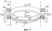
фиг. 2 - вид в перспективе трубчатой детали по фиг.1 перед ее соединением с другой трубчатой деталью кузнечной сваркой способом по настоящему изобретению;FIG. 2 is a perspective view of the tubular part of FIG. 1 before it is connected to another tubular part by blacksmith welding by the method of the present invention;
фиг.3 - сечение конца многоканальной трубчатой детали, нагреваемого двумя парами диаметрально противоположных электродов;figure 3 is a cross section of the end of a multichannel tubular part heated by two pairs of diametrically opposite electrodes;
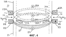
фиг.4 - вид в перспективе многоканальной трубчатой детали, показанной на фиг.3, перед ее соединением с другой многоканальной трубчатой деталью способом кузнечной сварки по настоящему изобретению; иFIG. 4 is a perspective view of the multi-channel tubular part shown in FIG. 3 before it is connected to another multi-channel tubular part by the blacksmith welding method of the present invention; FIG. and
фиг.5-10 - различные конфигурации многоканальных трубопроводов, концы которых можно нагревать, по существу, равномерно с использованием сборок из трех или более электродов согласно настоящему изобретению.5-10 are various configurations of multi-channel pipelines whose ends can be heated substantially uniformly using assemblies of three or more electrodes according to the present invention.
На фиг.1 показан конец стальной трубчатой детали 1, вокруг которого размещены две пары диаметрально противоположных электродов 2, 3 и 4, 5. Первая пара электродов 2, 3 прижата к внешней поверхности трубчатой детали 1 и передает ток 6 высокой частоты через стенку трубчатой детали 1, как показано стрелками 7. Сборка ферритовых стержней 8 служит для увеличения плотности тока в непосредственной близости от концов трубчатой детали 1 и прилегающей трубчатой детали (не показана).Figure 1 shows the end of the steel tubular part 1, around which are placed two pairs of diametrically
На фиг.2 показано, как концы 12, 12А двух прилегающих трубчатых деталей 1 и 1А нагреваются соответственно двумя комплектами диаметрально противоположных электродов 2, 3, 4, 5 и 2А, 3А, 4А, 5А. Концы 12 и 12А трубчатых деталей во время фазы нагревания расположены в нескольких миллиметрах друг от друга. Большее расстояние между стрелками 7 и 7А, обозначающими плотность тока, в средней части между электродами 2, 3 и 2А, 3А иллюстрирует, что плотность тока на середине расстояния между электродами меньше, чем плотность тока рядом с электродами 2, 3 и 2А, 3А. Это служит причиной возникновения разницы в скорости нагрева концов 12 и 12А трубчатых деталей и уменьшенного нагрева участка, расположенного на середине расстояния между электродами 2, 3 и 2А, 3А. Для уменьшения неравномерности скорости нагрева электроды 2, 3 и 2А, 3А регулярно отводят от внешней поверхности трубчатых деталей 1, 1А, и в это время другие электроды 4, 4А и 5, 5А прижимают к внешней поверхности трубчатых деталей 1, 1А и включают их для передачи тока высокой частоты через концы трубчатых деталей 1, 1А. За счет последовательной активации двух комплектов диаметрально противоположных электродов на каждом конце трубчатой детали снижается неравномерность нагрева концов трубчатых деталей.Figure 2 shows how the
Альтернативно электроды 2-5 и 2А-5А, показанные на фиг.2, можно одновременно прижимать к разнесенным концам трубчатых деталей 1 и 1А, если управлять переменным током, например, с помощью тиристоров, так, чтобы на первом этапе этого цикла пары диаметрально противоположных электродов 2А и 3 передавали положительный электрический ток, как показано знаком "+" на фиг.2, а другие электроды 2 и 3А передавали отрицательный ток, как показано знаком "-" на фиг.2. С другой стороны, на втором этапе цикла переменного тока электроды 2А и 3 передают отрицательный электрический ток, а другие электроды 2 и 3А передают положительный электрический ток на трубчатые детали 1 и 1А, тем самым нагревая концы 12 и 12А трубчатых деталей, по существу, одинаково.Alternatively, the electrodes 2-5 and 2A-5A shown in FIG. 2 can simultaneously be pressed against the spaced ends of the
Во время следующей фазы цикла нагрева электроды 2, 2А и 3, 3А не активны, а другие электроды 4, 5 и 4А, 5А активируются подобным же образом.During the next phase of the heating cycle, the
Температуру нагретых концов 12, 12А трубчатых деталей контролируют с помощью инфракрасного датчика температуры, и когда температура достигает уровня, достаточного для формирования кузнечного сварного шва, концы 12, 12А трубчатых деталей прижимают друг к другу так, чтобы сформировать кузнечный сварной шов. Концы 12, 12А трубчатых деталей могут быть профилированными и иметь меньшую толщину стенок по сравнению с другими участками трубчатых деталей 1, 1А для компенсации деформации нагретых до красного каления концов 12, 12А трубчатых деталей во время процесса кузнечной сварки с тем, чтобы сваренные трубчатые детали 1, 1А имели равномерные толщину стенок и внешний и внутренний диаметр.The temperature of the
Во время фазы нагрева и при перемещении концов трубчатых деталей 1, 1А по направлению друг к другу эти концы трубчатых деталей как снаружи, так и изнутри заключены в камеру 10, заполненную взрывобезопасной смесью продувочных газов, которая содержит более 75 об.% азота и менее 25 об.% водорода. Предпочтительная взрывобезопасная смесь продувочных газов для соединения трубчатых деталей 1, 1А, выполненных из углеродистой стали, содержит около 5 об.% водорода и около 95 об.% азота. Давление продувочного газа в той части камеры 10, которая находится снаружи относительно трубчатых деталей 1, 1А, выше, чем давление продувочных газов в части камеры 10, находящейся внутри трубчатых деталей 1, 1А, так что во время всего процесса нагрева продувочный газ течет вдоль концов 12, 12А трубчатых деталей 1, 1А, как показано стрелками 11, до тех пор, пока концы трубчатых деталей не будут прижаты и приварены друг к другу.During the heating phase and when moving the ends of the
Водород в продувочном газе вступает в реакцию с кислородом в окалине, образовавшейся в результате окисления на концах 12, 12А соединяемых трубчатых деталей 1, 1А, так что окалина, по меньшей мере, по существу, устраняется, и чистые металлические детали привариваются друг к другу с минимальным количеством включений окислившегося металла.Hydrogen in the purge gas reacts with oxygen in the scale resulting from the oxidation at the
Лабораторные эксперименты показали, что хорошее металлургическое соединение между трубчатыми деталями из углеродистой стали получается вышеописанным способом кузнечной сварки, когда продувочная текучая среда содержит около 5 об.% водорода и около 95 об.% азота. Эксперименты также подтвердили взрывобезопасность такого состава продувочного газа.Laboratory experiments have shown that a good metallurgical connection between carbon steel tubular parts is obtained by the above-described blacksmith welding method, when the purge fluid contains about 5 vol.% Hydrogen and about 95 vol.% Nitrogen. The experiments also confirmed the explosion safety of such a purge gas composition.
Предпочтительно концы трубчатых деталей зажаты в течение всего процесса кузнечной сварки в зажиме, который удерживает концы трубчатых деталей на заранее определенном расстоянии в 1-3 мм друг от друга во время фазы нагрева и который содержит механический упор, который препятствует осевому перемещению концов трубчатых деталей во время процесса кузнечной сварки, когда нагретые концы трубчатых деталей смещаются вдоль заранее определенного расстояния по направлению друг к другу и вжимаются друг в друга так, чтобы получить высококачественный кузнечный сварной шов без чрезмерной деформации нагретых концов трубчатых деталей.Preferably, the ends of the tubular parts are clamped during the entire forging process in a clamp that holds the ends of the tubular parts at a predetermined distance of 1-3 mm from each other during the heating phase and which contains a mechanical stop that prevents axial movement of the ends of the tubular parts during of the forging process, when the heated ends of the tubular parts are displaced along a predetermined distance towards each other and are pressed into each other so as to obtain high-quality th Forge weld without excessive deformation of the heated ends of the tubular parts.
Для удобства можно также включить электроды 2-5 и 2А-5А, чтобы провести послесварочную термообработку сваренных концов трубчатых деталей. Электрический ток 6, подаваемый на электроды во время послесварочной термообработки, будет меньше, чем во время фазы нагрева до операции кузнечной сварки, и им можно управлять в соответствии с температурой, измеренной инфракрасным(-и) датчиком(-ами) температуры так, чтобы температура сваренных кузнечной сваркой концов трубчатых деталей понижалась по заранее определенному графику.For convenience, you can also turn on the electrodes 2-5 and 2A-5A, to conduct post-welding heat treatment of the welded ends of the tubular parts. The electric current 6 supplied to the electrodes during the post-welding heat treatment will be less than during the heating phase before the forging operation, and it can be controlled in accordance with the temperature measured by the infrared temperature sensor (s) so that the temperature the ends of tubular parts welded by blacksmithing were lowered according to a predetermined schedule.
Качество полученного кузнечной сваркой шва можно проверить непосредственно после образования шва с помощью гибридной технологии электромагнитоакустического контроля, известной под названием ЕМАТ и описанной в патентах США №№5652389; 5760307; 5777229 и 6155117. В технологии ЕМАТ используется индукционная катушка, помещенная с одной стороны сварного шва, которая наводит магнитные поля, генерирующие электромагнитные силы в поверхности сварного шва. Эти силы затем создают механические возмущения, взаимодействуя с атомной структурой через процесс рассеяния. При электромагнитоакустическом генерировании преобразование происходит в поверхностном слое материала, т.е. поверхность металла является собственно преобразователем. Прием происходит обоюдно. Когда упругая волна сталкивается с поверхностью проводника в присутствии магнитного поля, в приемной катушке наводятся токи так же, как и при работе электрического генератора. Преимуществом этой технологии ЕМАТ-контроля сварных швов является то, что передающая и приемная индуктивные катушки не должны контактировать со сваренными деталями. Таким образом, контроль качества может проводиться непосредственно после формирования полученного кузнечной сваркой шва, когда сваренные трубчатые детали еще слишком горячи для физического контакта с контрольным зондом.The quality of the weld obtained by forge welding can be checked immediately after the weld is formed using the hybrid technology of electro-acoustic control, known as EMAT and described in US patent No. 56652389; 5,760,307; 5777229 and 6155117. EMAT technology uses an induction coil placed on one side of the weld, which induces magnetic fields that generate electromagnetic forces in the surface of the weld. These forces then create mechanical disturbances, interacting with the atomic structure through the scattering process. When electromagnetically generating, the transformation occurs in the surface layer of the material, i.e. metal surface is actually a converter. Reception takes place mutually. When an elastic wave collides with the surface of a conductor in the presence of a magnetic field, currents are induced in the receiving coil in the same way as when an electric generator was operating. The advantage of this EMAT control technology for welds is that the transmitting and receiving inductive coils should not come into contact with the welded parts. Thus, quality control can be carried out immediately after the formation of a weld obtained by forging, when the welded tubular parts are still too hot for physical contact with the control probe.
Способ и система по настоящему изобретению особенно полезны для сварки труб, применяющихся на нефтепромыслах и/или скважинных труб на нефте- и/или газодобывающих платформах или рядом с ними. К таким трубам могут относится эксплуатационные колонны длиной несколько километров, которые спускают в скважину после сварки секций колонны.The method and system of the present invention is particularly useful for welding pipes used in oil fields and / or downhole pipes on or near oil and / or gas production platforms. Such pipes may include production cores several kilometers long, which are lowered into the well after welding sections of the casing.
Альтернативно к таким трубам могут относиться нагревательные трубы, которые спускают в нагревательную скважину для передачи тепла в окружающий керогенный и/или нефтяной пласт для снижения вязкости и/или пиролиза керогена и/или других углеводородов in situ. Такие нагревательные трубы могут состоять из пары соосных труб, которые образуют электрическую цепь, по которой проходит электрический ток для производства тепла.Alternatively, such pipes may include heating pipes that are lowered into a heating well to transfer heat to the surrounding kerogen and / or oil reservoir to reduce the viscosity and / or pyrolysis of kerogen and / or other hydrocarbons in situ. Such heating pipes may consist of a pair of coaxial pipes that form an electrical circuit through which electric current flows to produce heat.
Предпочтительно, чтобы такие нагревательные или эксплуатационные колонны сваривались друг с другом, когда свариваемые трубы проходят, по существу, горизонтально, на линии сварки труб на поверхности земли, после чего трубы изгибают и вставляют в нагревательную или эксплуатационную скважину. Подходящие способы изгиба и вставки описаны в публикациях Международных заявок на патент WO 00/43630 и WO 00/43631, которые включены в настоящее описание путем данной ссылки. Предпочтительно скважинные трубы сваривают на горизонтальной сварочной линии рядом с устьем скважины и затем сгибают в большую петлю, которая образует дугу в по меньшей мере 270°, так, чтобы удаленный конец колонны труб проходил вертикально в устье скважины, а ближний конец колонны проходил горизонтально через сварочную установку. Альтернативно скважинные трубы сваривают друг с другом горизонтально, а затем изгибают в большую петлю на небольшом расстоянии от устья скважины. Когда всю колонну соберут и изогнут в эту большую петлю, собранную колонну транспортируют, например, по рельсам к устью скважины и затем вставляют в скважину, как это описано в публикации Международной заявки на патент WO 00/43631. Последняя из описанных технологий сборки труб позволяет собирать колонны труб на центральной сварочной установке, расположенной в центральной точке нефтяного месторождения, где несколько колонн могут собираться и храниться до момента их транспортировки к устью скважины, после чего их быстро вставляют в скважину или скважины, так что нарушения в эксплуатации скважины или при операциях нагрева сводятся к минимуму.It is preferable that such heating or production columns are welded together when the pipes to be welded extend substantially horizontally on the pipe welding line on the surface of the earth, after which the pipes are bent and inserted into the heating or production well. Suitable bending and insertion methods are described in publications of International patent applications WO 00/43630 and WO 00/43631, which are incorporated into this description by reference. Preferably, the downhole pipes are welded on a horizontal welding line near the wellhead and then bent into a large loop that forms an arc of at least 270 °, so that the distal end of the pipe string extends vertically at the wellhead and the proximal end of the column extends horizontally through the welding installation. Alternatively, the borehole pipes are welded together horizontally and then bent into a large loop at a small distance from the wellhead. When the entire column is assembled and bent into this large loop, the assembled column is transported, for example, on rails to the wellhead and then inserted into the well, as described in International Patent Application Publication WO 00/43631. The last of the described pipe assembly technologies allows pipe columns to be assembled at a central welding unit located at the central point of the oil field, where several columns can be collected and stored until they are transported to the wellhead, after which they are quickly inserted into the well or wells, so that violations in well operation or during heating operations are minimized.
На фиг.3 показан конец стальной многоканальной трубчатой детали 21, вокруг которой установлены две пары диаметрально противоположных электродов 22, 23 и 24, 25. Трубчатая деталь 1 содержит продольную и диагональную разделительную стенку 29, которая создает два полуцилиндрических канала 30 и 31 внутри трубчатой детали 21.Figure 3 shows the end of a steel multi-channel
Первая пара электродов 22, 23 прижата к внешней поверхности трубчатой детали 21 и передает ток 26 высокой частоты через стенку трубчатой детали 21 и разделительную стенку 29, как показано стрелками 27, 27А. Комплект ферритовых стержней 28 служит для увеличения плотности тока в непосредственной близости от концов трубчатой детали 21 и прилегающей трубчатой детали (не показана). Когда первый диагональный комплект электродов 22, 23 активируют, большая часть электрического тока проходит через диагональную разделительную стенку 29, тем самым преимущественно нагревая конец указанной разделительной стенки 29, а когда после этого активируют электроды 24, 25, большая часть электрического тока высокой частоты проходит через стенку трубчатой детали 21. Мощность, подаваемая к комплектам электродов 22, 23 и 24, 25, и длительность периодов, в течение которых комплекты электродов поочередно активируются, регулируется так, что концы стенок трубчатой детали 21 и разделительной стенки 29 нагреваются равномерно до заранее определенной температуры.The first pair of
На фиг.4 показано, как концы 32, 32А двух прилегающих многоканальных трубчатых деталей 21 и 21А нагревают соответственно двумя комплектами диаметрально противоположных электродов 22, 23, 24, 25 и 22А, 23А, 24А, 25А. Во время фазы нагрева концы 32 и 32А трубчатых деталей расположены на расстоянии до нескольких миллиметров друг от друга, чтобы создать емкостной эффект между концами 32, 32А трубчатых деталей, который стимулирует протекание электрического тока на концах 32 и 32А трубчатых деталей. Увеличенное расстояние между стрелками 27 и 27А, обозначающими плотность тока, на середине расстояния между электродами иллюстрирует, что плотность тока на середине расстояния между этими электродами меньше, чем плотность тока рядом с электродами 22, 23 и 22А, 23А. Это вызывает изменение скорости нагрева концов 32 и 32А трубчатых деталей и уменьшает нагрев на участке, расположенном на середине расстояния между электродами 22, 23 и 22А, 23А. Для уменьшения неравномерности скорости нагрева электроды 22, 23 и 22А, 23А можно регулярно отводить от внешней поверхности трубчатых деталей 21, 21А, и в это время прижимать к поверхности трубчатых деталей 21, 21А другие электроды 24, 24А и 25, 25А и активировать их для передачи тока высокой частоты через концы трубчатых деталей 21, 21А. Последовательное включение двух комплектов диаметрально противоположных электродов на каждом конце трубчатых деталей снижает неравномерность нагрева концов трубчатых деталей.Figure 4 shows how the ends 32, 32A of two adjacent multichannel
Все электроды 22-25 и 22А-25А, показанные на фиг.4, могут одновременно прижиматься к разнесенным концам 21 и 21А трубчатых деталей, если переменным током управляют, например, с помощью тиристоров так, чтобы в первой части цикла электроды 22А и 23 передавали положительный электрический ток, как показано знаком "+" на фиг.4, а другие электроды 22, 23, 24А и 25А передавали отрицательный электрический ток, как показано знаком "-" на фиг.4. С другой стороны, во второй части цикла переменного тока электроды 22А и 23 будут передавать отрицательный электрический ток, а другие электроды 22 и 23А будут передавать положительный ток на трубчатые детали 21 и 21А, тем самым нагревая их концы 32, 32А и концы диагональных разделительных стенок 29, 29А, по существу, равномерно.All electrodes 22-25 and 22A-25A shown in FIG. 4 can simultaneously be pressed against the spaced ends 21 and 21A of the tubular parts if the alternating current is controlled, for example, by thyristors so that in the first part of the cycle, the
Температуру нагретых концов 32, 32А трубчатых деталей и диагональных разделительных стенок 29, 29А можно контролировать с помощью пирометрического инфракрасного датчика температуры, и когда контролируемая температура достигнет величины, пригодной для образования кузнечного сварного шва, концы 32, 32А трубчатых деталей и противоположные концы диагональных разделительных стенок 29, 29А прижимают друг к другу так, чтобы получить кузнечный сварной шов. Концы 32, 32А трубчатых деталей могут быть профилированными и иметь меньшую толщину стенки по сравнению с другими участками трубчатых деталей 21, 21А с тем, чтобы компенсировать деформацию нагретых до красного каления концов 32, 32А трубчатых деталей во время процесса кузнечной сварки, так что сваренные трубчатые детали 21, 21А имеют равномерную толщину стенки и внешний и внутренний диаметр.The temperature of the heated ends 32, 32A of the tubular parts and the
Во время фазы нагрева и при перемещении концов трубчатых деталей 21, 21А по направлению друг к другу эти концы трубчатых деталей как снаружи, так и изнутри заключены в камеру 33, заполненную взрывобезопасной смесью продувочных газов, которая содержит более 75 об.% азота и менее 25 об.% водорода. Предпочтительная взрывобезопасная смесь продувочных газов для соединения трубчатых деталей 21, 21А, выполненных из углеродистой стали, содержит около 5 об.% водорода и около 95 об.% азота. Давление продувочного газа в той части камеры 33, которая находится снаружи относительно трубчатых деталей 21, 21А, выше, чем давление продувочных газов в части камеры 10, находящейся внутри трубчатых деталей 21, 21А, так что во время всего процесса нагрева продувочный газ течет вдоль концов трубчатых деталей 21, 21А, как показано стрелками 34, до тех пор, пока концы трубчатых деталей не будут приварены друг к другу.During the heating phase and when moving the ends of the
Водород в продувочном газе вступает в реакцию с кислородом в окалине на концах 32, 32А соединяемых трубчатых деталей 21, 21А, так что окалина, по меньшей мере, по существу, устраняется, и чистые металлические детали привариваются друг к другу с минимальным количеством включении окислившегося металла.Hydrogen in the purge gas reacts with oxygen in the scale at the
Предпочтительно концы трубчатых деталей зажаты в течение всего процесса кузнечной сварки в зажиме, который удерживает концы трубчатых деталей на заранее определенном расстоянии в 1-3 мм друг от друга во время фазы нагрева и который содержит механический упор, который препятствует осевому перемещению концов трубчатых деталей во время процесса кузнечной сварки, когда нагретые концы трубчатых деталей смещаются вдоль заранее определенного расстояния по направлению друг к другу и вжимаются друг в друга так, чтобы получить высококачественный кузнечный сварной шов без чрезмерной деформации нагретых концов трубчатых деталей.Preferably, the ends of the tubular parts are clamped during the entire forging process in a clamp that holds the ends of the tubular parts at a predetermined distance of 1-3 mm from each other during the heating phase and which contains a mechanical stop that prevents axial movement of the ends of the tubular parts during of the forging process, when the heated ends of the tubular parts are displaced along a predetermined distance towards each other and are pressed into each other so as to obtain high-quality th Forge weld without excessive deformation of the heated ends of the tubular parts.
Для удобства можно включить электроды 22-25 и 22А-25А, чтобы провести послесварочную термообработку сваренных концов трубчатых деталей. Электрический ток 6, подаваемый на электроды во время послесварочной термообработки, будет меньше, чем во время фазы нагрева до операции кузнечной сварки, и им можно управлять в соответствии с температурой, измеренной инфракрасным(-и) датчиком(-ами) температуры, так, чтобы температура сваренных кузнечной сваркой концов трубчатых деталей понижалась по заранее определенному графику.For convenience, you can turn on the electrodes 22-25 and 22A-25A to conduct post-welding heat treatment of the welded ends of tubular parts. The electric current 6 supplied to the electrodes during the post-welding heat treatment will be less than during the heating phase before the forging operation, and it can be controlled in accordance with the temperature measured by the infrared temperature sensor (s), so that the temperature of the ends of tubular parts welded by blacksmithing decreased according to a predetermined schedule.
На фиг.5-10 показаны различные конфигурации многоканальных труб, которые можно нагревать, по существу, равномерно с помощью различных конфигураций распределенных по окружности электродных сборок.Figures 5-10 show various configurations of multi-channel pipes that can be heated substantially uniformly using various configurations of circumferentially distributed electrode assemblies.
На фиг.5 показан конец цилиндрической трубчатой детали 50, внутренняя полость которой разделена на четыре канала двумя диагональными разделительными стенками 51, которые пересекают друг друга под прямым углом. Восемь электродов комплекта расположены с интервалом 45° вокруг внешней поверхности трубчатой детали 50, причем комплект содержит четыре основных электрода 52, показанных квадратами, и четыре вспомогательных электрода 53, показанных кружками. Основные электроды 52 и вспомогательные электроды 53 включают попеременно, и когда основные электроды 52 включены, они пропускают электрический ток высокой частоты главным образом через концы диагональных разделительных стенок 51, а когда после них включают вспомогательные электроды 53, они пропускают электрический ток высокой частоты через стенку трубчатой детали 50. Основные и вспомогательные электроды 52 и 53 включают последовательно до тех пор, пока концы трубчатой детали и разделительных стенок 51 не достигнут заранее определенной температуры, после чего нагретые концы трубчатой детали 50 и разделительных стенок 51 прижимают к прилегающему концу другой трубчатой детали (не показана), которая также имеет две диагональные разделительные стенки (не показаны), по существу, такие же, как описано со ссылками на фиг.4.Figure 5 shows the end of a cylindrical
На фиг.6 показана многоканальная трубная сборка, которая содержит стальную трубу 61 большого диаметра, приваренную к стальной трубе 62 меньшего диаметра. Четыре электрода 64 комплекта прижаты с выбранными угловыми интервалами к внешним поверхностям труб 61 и 62 так, что концы труб 61 и 62 нагреваются, по существу, равномерно электрическим током высокой частоты, текущим по концам труб от электродов 64. Достижению равномерности нагрева концов труб может в еще большей степени способствовать изменение электрического тока и/или напряжения, подаваемого на разные электроды 64, и/или циклическая активация разных пар электродов 64.Figure 6 shows a multi-channel pipe assembly, which contains a large
На фиг.7 показана многоканальная трубная сборка, которая содержит стальную трубу 71 большого диаметра, внутри которой приварена стальная труба 72 меньшего диаметра. Четыре электрода 74 комплекта прижаты с выбранными угловыми интервалами к поверхностям труб 71 и 72. Непрерывно меняющиеся полярности электродов 74 таковы, что через концы сегментов трубы между электродами 74 протекает, по существу, равномерный электрический ток высокой частоты, тем самым, по существу, равномерно нагревая концы обеих труб 71 и 72. Один из электродов 74 расположен внутри стальной трубы 71 большого диаметра с помощью оправки, которую можно вставлять в трубу 71 большого диаметра во время процесса кузнечной сварки и которая извлекается из трубы по завершении операции кузнечной сварки.7 shows a multi-channel pipe assembly, which contains a
На фиг.8 показана многоканальная трубная сборка, которая содержит стальную трубу 81 большого диаметра, внутри которой приварены две стальные трубы 82 и 83 меньшего диаметра. Концы труб нагревают комплектом из шести электродов 84, имеющих разные полярности, и тем самым подают электрический ток высокой частоты на сегменты труб между соседними электродами. Электроды 84 могут включаться циклически и управляться тиристорами для, по существу, равномерного нагрева концов труб 81, 82 и 83 большого и меньших диаметров.On Fig shows a multi-channel pipe assembly, which contains a
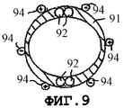
На фиг.9 показана многоканальная трубная сборка, которая содержит стальную трубу 91 большого диаметра и две пары управляющих каналов 92 меньшего диаметра, которые проходят в стенке трубы 91 большого диаметра в диаметрально противоположных положениях. Шесть электродов 94 комплекта прижаты с выбранными угловыми интервалами к внешней поверхности трубы 91 большого диаметра так, что концы трубы 91 и прилегающей аналогичной трубы (не показана) нагреваются, по существу, равномерно, после чего концы труб сжимаются друг с другом, и формируется кузнечный сварной шов.Figure 9 shows a multi-channel pipe assembly, which contains a
На фиг.10 показана многоканальная трубная сборка, которая содержит пакет из трех стальных труб 101, 102, 103, которые сварены друг с другом. Концы труб 101, 102, 103 нагревают, по существу, равномерно сборкой из трех электродов 104, которые включаются циклически как вращающийся трехфазный узел. Факультативно можно установить комплект из трех электродов 105, расположенных рядом с теми местами, в которых стальные трубы 101, 102, 103 сварены друг с другом, для того, чтобы нагревать сегменты труб, расположенных в центральной области пакета. Сборки из электродов 104 и 105 могут включаться попеременно и управляться так, чтобы концы труб нагревались, по существу, равномерно.Figure 10 shows a multi-channel pipe assembly, which contains a package of three
Предпочтительно используемая в способе продувочная смесь текучих сред содержит восстановительную текучую среду и инертный газ. При этом жидкий или твердый восстановительный агент наносят кистью или распыляют на концы трубчатых деталей, а инертный газ нагнетают в указанное пространство, после чего восстановительный агент, по меньшей мере частично испаряется при нагреве концов трубчатых деталей, и испарившийся восстановительный агент смешивается с нагнетаемым инертным газом с формированием на месте (in situ) продувочной газовой смеси, содержащей менее 25 об.% испарившегося восстановительного агента и более 75 об.%, по существу, инертного газа.Preferably used in the method of purging a mixture of fluids contains a reducing fluid and an inert gas. In this case, a liquid or solid reducing agent is applied by brush or sprayed onto the ends of the tubular parts, and an inert gas is injected into the indicated space, after which the reducing agent is at least partially vaporized by heating the ends of the tubular parts, and the vaporized reducing agent is mixed with the injected inert gas with the formation of an in situ purge gas mixture containing less than 25 vol.% of the evaporated reducing agent and more than 75 vol.%, essentially inert gas.
Более предпочтительно, этот жидкий или твердый восстановительный агент содержит очищающую жидкость, такую как, например, соляная кислота, и восстановительный агент, такой как перекись водорода, порошок буры и/или гидрид щелочного металла или бериллия.More preferably, this liquid or solid reducing agent contains a cleaning liquid, such as, for example, hydrochloric acid, and a reducing agent, such as hydrogen peroxide, borax powder and / or alkali metal or beryllium hydride.
Следует понимать, что знаки "+" и "-", показанные в иллюстрируемой электродной сборке, являются чисто иллюстративными и что полярности различных электродов меняются постоянно по синусоиде, когда электрический ток высокой частоты поступает через электроды в соседние сегменты стенок трубчатых деталей, концы которых подвергаются кузнечной сварке.It should be understood that the signs “+” and “-” shown in the illustrated electrode assembly are purely illustrative and that the polarities of the various electrodes are constantly changing in a sinusoid when a high-frequency electric current flows through the electrodes into adjacent segments of the walls of the tubular parts, the ends of which are exposed forge welding.
Claims (21)
Applications Claiming Priority (2)
| Application Number | Priority Date | Filing Date | Title |
|---|---|---|---|
| EP01205146.2 | 2001-12-31 | ||
| EP01205146 | 2001-12-31 |
Publications (2)
| Publication Number | Publication Date |
|---|---|
| RU2004123626A RU2004123626A (en) | 2005-05-10 |
| RU2297906C2 true RU2297906C2 (en) | 2007-04-27 |
Family
ID=8181539
Family Applications (1)
| Application Number | Title | Priority Date | Filing Date |
|---|---|---|---|
| RU2004123626/02A RU2297906C2 (en) | 2001-12-31 | 2002-12-31 | Method for joining tubular parts by forge welding |
Country Status (13)
| Country | Link |
|---|---|
| US (1) | US7199325B2 (en) |
| EP (1) | EP1463603B1 (en) |
| CN (1) | CN100335226C (en) |
| AT (1) | ATE326308T1 (en) |
| AU (1) | AU2002361240B2 (en) |
| BR (1) | BR0215332B1 (en) |
| DE (1) | DE60211559T2 (en) |
| EA (1) | EA009297B1 (en) |
| MY (1) | MY128610A (en) |
| NO (1) | NO331458B1 (en) |
| OA (1) | OA12753A (en) |
| RU (1) | RU2297906C2 (en) |
| WO (1) | WO2003055635A1 (en) |
Families Citing this family (12)
| Publication number | Priority date | Publication date | Assignee | Title |
|---|---|---|---|---|
| CA2526171C (en) * | 2003-06-10 | 2011-11-08 | Noetic Engineering Inc. | Shear assisted solid state weld and method of forming |
| US8205674B2 (en) | 2006-07-25 | 2012-06-26 | Mountain West Energy Inc. | Apparatus, system, and method for in-situ extraction of hydrocarbons |
| NO329186B1 (en) * | 2007-11-09 | 2010-09-06 | Amr Engineering As | Device and advanced feed for forging and diffusion welding |
| DE102007058804A1 (en) * | 2007-12-06 | 2009-06-10 | Linde Ag | Forming device and method for forming |
| EP2401470A2 (en) * | 2009-02-25 | 2012-01-04 | Weatherford/Lamb, Inc. | Pipe handling system |
| GB0913218D0 (en) * | 2009-07-30 | 2009-09-02 | Tubefuse Applic V O F | Method and apparatus for passing an electric current through an object |
| GB0913217D0 (en) * | 2009-07-30 | 2009-09-02 | Tubefuse Applic V O F | Welding method and system |
| GB0913216D0 (en) * | 2009-07-30 | 2009-09-02 | Tubefuse Applic V O F | Heating method and apparatus |
| FR2963899B1 (en) * | 2010-08-17 | 2013-05-03 | Air Liquide | METHOD AND APPARATUS FOR ARC WELDING WITH MIG / MAG TORCH ASSOCIATED WITH TIG TORCH |
| JP5909014B1 (en) * | 2015-06-08 | 2016-04-26 | オリジン電気株式会社 | Bonding member manufacturing method and bonding member manufacturing apparatus |
| CN108746977B (en) * | 2018-05-02 | 2021-02-09 | 中国航发北京航空材料研究院 | Installation method of plunger pump cylinder body and copper sleeve |
| US11673204B2 (en) | 2020-11-25 | 2023-06-13 | The Esab Group, Inc. | Hyper-TIG welding electrode |
Family Cites Families (25)
| Publication number | Priority date | Publication date | Assignee | Title |
|---|---|---|---|---|
| US456625A (en) * | 1891-07-28 | Frederic malfait | ||
| US2719207A (en) * | 1953-01-23 | 1955-09-27 | Smith Corp A O | Apparatus and method for producing a non-oxidizing atmosphere for flash welding |
| US3625258A (en) * | 1970-03-16 | 1971-12-07 | Warren Petroleum Corp | Multipassage pipe |
| US4216896A (en) * | 1977-02-11 | 1980-08-12 | Santa Fe International Corporation | Automatic pipe welding apparatus and method |
| NO152590C (en) * | 1982-04-13 | 1985-10-23 | Per H Moe | PROCEDURE FOR JOINING PARTS OF METAL BY DIFFUSION WELDING. |
| CA1237002A (en) * | 1983-10-13 | 1988-05-24 | Per H. Moe | Method for joining tubular parts of metal by forge/diffusion welding |
| NO155607C (en) * | 1985-01-04 | 1987-04-29 | Per H Moe | PROCEDURE FOR BUTT WELDING BY RESISTANCE HEATING OF RUBBER OR BOLT-SHAPED PARTS OR PARTS OF METAL WITH HIGH-FREQUENCY CURRENT. |
| US4728760A (en) * | 1986-08-11 | 1988-03-01 | Fmc Corporation | Induction heating pressure welding with rotary bus bar joint |
| NO164583C (en) * | 1986-11-20 | 1990-10-24 | Per H Moe | DEVICE HEATING DEVICE. |
| NO166396C (en) * | 1989-02-01 | 1991-07-17 | Per H Moe | PROCEDURES FOR SMALL WELDING E.L. |
| GB8910118D0 (en) | 1989-05-03 | 1989-06-21 | Shell Int Research | Method and device for joining well tubulars |
| DE4200199A1 (en) * | 1992-01-07 | 1993-07-08 | Emhart Inc | METHOD FOR ELECTRICALLY WELDING TWO WELDED PARTS |
| US5347101A (en) * | 1994-02-07 | 1994-09-13 | Mcdermott International, Inc. | Automatic tracking system for pipeline welding |
| CA2144597C (en) * | 1994-03-18 | 1999-08-10 | Paul J. Latimer | Improved emat probe and technique for weld inspection |
| NO942441D0 (en) * | 1994-06-28 | 1994-06-28 | Per H Moe | Procedure for welding |
| EP0771419A4 (en) * | 1994-07-18 | 1999-06-23 | Babcock & Wilcox Co | Sensor transport system for flash butt welder |
| CA2211691A1 (en) * | 1995-02-15 | 1996-08-22 | Robert W. Carnes | Determining, controlling electrical resistance |
| US5652389A (en) * | 1996-05-22 | 1997-07-29 | The United States Of America As Represented By The Secretary Of Commerce | Non-contact method and apparatus for inspection of inertia welds |
| US5686002A (en) * | 1996-08-12 | 1997-11-11 | Tri Tool Inc. | Method of welding |
| WO1998033619A1 (en) | 1997-02-04 | 1998-08-06 | Shell Internationale Research Maatschappij B.V. | Method and device for joining oilfield tubulars |
| DE69810308T2 (en) * | 1997-08-19 | 2003-08-14 | Shell Int Research | DEVICE FOR AMORPHOUSLY CONNECTING TUBES |
| WO1999022901A1 (en) * | 1997-11-03 | 1999-05-14 | Messer Griesheim Gmbh | Protective gas for tig welding |
| GB2345016B (en) * | 1998-12-24 | 2003-04-02 | Saipem Spa | Method and apparatus for welding pipes together |
| NL1011069C2 (en) | 1999-01-19 | 2000-07-20 | Well Engineering Partners B V | Method and installation for inserting a pipe into a borehole in the ground. |
| US6155117A (en) * | 1999-03-18 | 2000-12-05 | Mcdermott Technology, Inc. | Edge detection and seam tracking with EMATs |
-
2002
- 2002-12-27 MY MYPI20024908A patent/MY128610A/en unknown
- 2002-12-31 CN CNB028264754A patent/CN100335226C/en not_active Expired - Fee Related
- 2002-12-31 WO PCT/EP2002/014865 patent/WO2003055635A1/en active Application Filing
- 2002-12-31 AU AU2002361240A patent/AU2002361240B2/en not_active Ceased
- 2002-12-31 RU RU2004123626/02A patent/RU2297906C2/en not_active IP Right Cessation
- 2002-12-31 DE DE60211559T patent/DE60211559T2/en not_active Expired - Lifetime
- 2002-12-31 BR BRPI0215332-7A patent/BR0215332B1/en not_active IP Right Cessation
- 2002-12-31 AT AT02796758T patent/ATE326308T1/en not_active IP Right Cessation
- 2002-12-31 US US10/500,316 patent/US7199325B2/en not_active Expired - Fee Related
- 2002-12-31 EP EP02796758A patent/EP1463603B1/en not_active Expired - Lifetime
- 2002-12-31 EA EA200701311A patent/EA009297B1/en not_active IP Right Cessation
- 2002-12-31 OA OA1200400182A patent/OA12753A/en unknown
-
2004
- 2004-07-30 NO NO20043234A patent/NO331458B1/en not_active IP Right Cessation
Also Published As
| Publication number | Publication date |
|---|---|
| OA12753A (en) | 2006-07-03 |
| ATE326308T1 (en) | 2006-06-15 |
| US20050092715A1 (en) | 2005-05-05 |
| CN100335226C (en) | 2007-09-05 |
| DE60211559D1 (en) | 2006-06-22 |
| NO20043234L (en) | 2004-07-30 |
| EA200701311A1 (en) | 2007-10-26 |
| DE60211559T2 (en) | 2006-10-26 |
| EP1463603A1 (en) | 2004-10-06 |
| EP1463603B1 (en) | 2006-05-17 |
| NO331458B1 (en) | 2012-01-09 |
| US7199325B2 (en) | 2007-04-03 |
| RU2004123626A (en) | 2005-05-10 |
| BR0215332B1 (en) | 2010-12-14 |
| MY128610A (en) | 2007-02-28 |
| CN1610595A (en) | 2005-04-27 |
| WO2003055635A1 (en) | 2003-07-10 |
| EA009297B1 (en) | 2007-12-28 |
| AU2002361240A1 (en) | 2003-07-15 |
| AU2002361240B2 (en) | 2007-11-22 |
| BR0215332A (en) | 2004-11-16 |
Similar Documents
| Publication | Publication Date | Title |
|---|---|---|
| RU2297906C2 (en) | Method for joining tubular parts by forge welding | |
| US6896171B2 (en) | EMAT weld inspection | |
| US7474221B2 (en) | Marking of pipe joints | |
| US7282663B2 (en) | Forge welding process | |
| US20070158390A1 (en) | Forge welding tubulars | |
| CA2416006A1 (en) | Heater cable and method for manufacturing | |
| US20080237308A1 (en) | Forge welding method | |
| US9308600B2 (en) | Arc guiding, gripping and sealing device for a magnetically impelled butt welding rig | |
| CN1271312C (en) | Electrical well heating system and method | |
| US20060169752A1 (en) | Forge welding of heavy duty tubulars | |
| FI90636C (en) | Procedure and device for soldering and brazing | |
| US20150196968A1 (en) | Enhanced Arc Control for Magnetically Impelled Butt Welding | |
| USRE29016E (en) | Welding and forming method | |
| US20130092670A1 (en) | Enhanced magnetically impelled arc butt wielding (miab) technology | |
| CA2493735C (en) | Forge welding of tubulars | |
| EP2222432B1 (en) | Apparatuses for and methods of forge welding elongated articles with electrodes and an induction coil | |
| SU551138A1 (en) | Non-consumable electrode arc welding torch in shielding gases | |
| TH22536A (en) | Process and equipment for resin hose connection |
Legal Events
| Date | Code | Title | Description |
|---|---|---|---|
| MM4A | The patent is invalid due to non-payment of fees |
Effective date: 20080101 |