RU2296748C2 - Urea producing apparatus - Google Patents
Urea producing apparatus Download PDFInfo
- Publication number
- RU2296748C2 RU2296748C2 RU2005102067/04A RU2005102067A RU2296748C2 RU 2296748 C2 RU2296748 C2 RU 2296748C2 RU 2005102067/04 A RU2005102067/04 A RU 2005102067/04A RU 2005102067 A RU2005102067 A RU 2005102067A RU 2296748 C2 RU2296748 C2 RU 2296748C2
- Authority
- RU
- Russia
- Prior art keywords
- heat exchanger
- heat
- installation according
- heat exchangers
- reactor
- Prior art date
Links
Images


Classifications
-
- C—CHEMISTRY; METALLURGY
- C07—ORGANIC CHEMISTRY
- C07C—ACYCLIC OR CARBOCYCLIC COMPOUNDS
- C07C273/00—Preparation of urea or its derivatives, i.e. compounds containing any of the groups, the nitrogen atoms not being part of nitro or nitroso groups
- C07C273/02—Preparation of urea or its derivatives, i.e. compounds containing any of the groups, the nitrogen atoms not being part of nitro or nitroso groups of urea, its salts, complexes or addition compounds
- C07C273/04—Preparation of urea or its derivatives, i.e. compounds containing any of the groups, the nitrogen atoms not being part of nitro or nitroso groups of urea, its salts, complexes or addition compounds from carbon dioxide and ammonia
-
- B—PERFORMING OPERATIONS; TRANSPORTING
- B01—PHYSICAL OR CHEMICAL PROCESSES OR APPARATUS IN GENERAL
- B01J—CHEMICAL OR PHYSICAL PROCESSES, e.g. CATALYSIS OR COLLOID CHEMISTRY; THEIR RELEVANT APPARATUS
- B01J19/00—Chemical, physical or physico-chemical processes in general; Their relevant apparatus
- B01J19/0006—Controlling or regulating processes
- B01J19/0013—Controlling the temperature of the process
-
- F—MECHANICAL ENGINEERING; LIGHTING; HEATING; WEAPONS; BLASTING
- F28—HEAT EXCHANGE IN GENERAL
- F28D—HEAT-EXCHANGE APPARATUS, NOT PROVIDED FOR IN ANOTHER SUBCLASS, IN WHICH THE HEAT-EXCHANGE MEDIA DO NOT COME INTO DIRECT CONTACT
- F28D9/00—Heat-exchange apparatus having stationary plate-like or laminated conduit assemblies for both heat-exchange media, the media being in contact with different sides of a conduit wall
- F28D9/0006—Heat-exchange apparatus having stationary plate-like or laminated conduit assemblies for both heat-exchange media, the media being in contact with different sides of a conduit wall the plate-like or laminated conduits being enclosed within a pressure vessel
-
- F—MECHANICAL ENGINEERING; LIGHTING; HEATING; WEAPONS; BLASTING
- F28—HEAT EXCHANGE IN GENERAL
- F28D—HEAT-EXCHANGE APPARATUS, NOT PROVIDED FOR IN ANOTHER SUBCLASS, IN WHICH THE HEAT-EXCHANGE MEDIA DO NOT COME INTO DIRECT CONTACT
- F28D9/00—Heat-exchange apparatus having stationary plate-like or laminated conduit assemblies for both heat-exchange media, the media being in contact with different sides of a conduit wall
- F28D9/0031—Heat-exchange apparatus having stationary plate-like or laminated conduit assemblies for both heat-exchange media, the media being in contact with different sides of a conduit wall the conduits for one heat-exchange medium being formed by paired plates touching each other
-
- F—MECHANICAL ENGINEERING; LIGHTING; HEATING; WEAPONS; BLASTING
- F28—HEAT EXCHANGE IN GENERAL
- F28F—DETAILS OF HEAT-EXCHANGE AND HEAT-TRANSFER APPARATUS, OF GENERAL APPLICATION
- F28F3/00—Plate-like or laminated elements; Assemblies of plate-like or laminated elements
- F28F3/02—Elements or assemblies thereof with means for increasing heat-transfer area, e.g. with fins, with recesses, with corrugations
- F28F3/04—Elements or assemblies thereof with means for increasing heat-transfer area, e.g. with fins, with recesses, with corrugations the means being integral with the element
-
- B—PERFORMING OPERATIONS; TRANSPORTING
- B01—PHYSICAL OR CHEMICAL PROCESSES OR APPARATUS IN GENERAL
- B01J—CHEMICAL OR PHYSICAL PROCESSES, e.g. CATALYSIS OR COLLOID CHEMISTRY; THEIR RELEVANT APPARATUS
- B01J2219/00—Chemical, physical or physico-chemical processes in general; Their relevant apparatus
- B01J2219/00049—Controlling or regulating processes
- B01J2219/00051—Controlling the temperature
- B01J2219/00074—Controlling the temperature by indirect heating or cooling employing heat exchange fluids
- B01J2219/00076—Controlling the temperature by indirect heating or cooling employing heat exchange fluids with heat exchange elements inside the reactor
- B01J2219/00085—Plates; Jackets; Cylinders
-
- F—MECHANICAL ENGINEERING; LIGHTING; HEATING; WEAPONS; BLASTING
- F28—HEAT EXCHANGE IN GENERAL
- F28F—DETAILS OF HEAT-EXCHANGE AND HEAT-TRANSFER APPARATUS, OF GENERAL APPLICATION
- F28F2250/00—Arrangements for modifying the flow of the heat exchange media, e.g. flow guiding means; Particular flow patterns
- F28F2250/10—Particular pattern of flow of the heat exchange media
- F28F2250/102—Particular pattern of flow of the heat exchange media with change of flow direction
-
- Y—GENERAL TAGGING OF NEW TECHNOLOGICAL DEVELOPMENTS; GENERAL TAGGING OF CROSS-SECTIONAL TECHNOLOGIES SPANNING OVER SEVERAL SECTIONS OF THE IPC; TECHNICAL SUBJECTS COVERED BY FORMER USPC CROSS-REFERENCE ART COLLECTIONS [XRACs] AND DIGESTS
- Y02—TECHNOLOGIES OR APPLICATIONS FOR MITIGATION OR ADAPTATION AGAINST CLIMATE CHANGE
- Y02P—CLIMATE CHANGE MITIGATION TECHNOLOGIES IN THE PRODUCTION OR PROCESSING OF GOODS
- Y02P20/00—Technologies relating to chemical industry
- Y02P20/141—Feedstock
Abstract
Description
Область техники, к которой относится изобретениеFIELD OF THE INVENTION
Настоящее изобретение относится к так называемой "десорбционной установке" для получения мочевины из аммиака и диоксида углерода. Изобретение относится, в частности, к секции высокого давления установки для получения мочевины указанного выше типа, состоящей из реактора синтеза мочевины и конденсатора или реактора синтеза мочевины, десорбера и конденсатора.The present invention relates to a so-called "desorption unit" for producing urea from ammonia and carbon dioxide. The invention relates in particular to a high-pressure section of an apparatus for producing urea of the above type, consisting of a urea synthesis reactor and a condenser or a urea synthesis reactor, a stripper and a condenser.
Уровень техникиState of the art
При взаимодействии аммиака и диоксида углерода при определенных по давлению и температуре условиях получают водный раствор, содержащий мочевину, карбамат аммония и свободный аммиак (т.е. аммиак, не связанный с карбаматом), и смесь газов, содержащую аммиак, диоксид углерода, воду (в виде водяного пара) и возможно инертные газы.The interaction of ammonia and carbon dioxide under conditions determined by pressure and temperature gives an aqueous solution containing urea, ammonium carbamate and free ammonia (i.e. ammonia not bound to carbamate), and a gas mixture containing ammonia, carbon dioxide, water ( in the form of water vapor) and possibly inert gases.
При получении мочевины методом десорбции содержащий мочевину выходящий из реактора синтеза водный раствор в соответствующем десорбере подвергают тепловой обработке, в результате которой происходит разложение карбамата на аммиак и диоксид углерода, с одновременной десорбцией (например, тем же диоксидом углерода, который подают на установку для получения мочевины) и выделением из раствора потока газа, содержащего бóльшую часть не вступивших в реакцию аммиака и диоксида углерода. Эти газы вместе с используемым для десорбции диоксидом углерода затем в соответствующем конденсаторе (известном как конденсатор карбамата высокого давления) снова конденсируют в карбамат, который возвращают в реактор синтеза. Аммиак и диоксид углерода, которые содержатся в газообразном состоянии в выходящей из реактора реакционной смеси, обычно превращают в карбамат аммония, в частности абсорбцией в соответствующем конденсаторе (так называемом скруббере) с использованием потока карбамата, подаваемого в конденсатор из секции выделения (регенерации) мочевины. Выходящий из скруббера поток карбамата пропускают через конденсатор карбамата высокого давления и возвращают обратно в реактор синтеза.In the preparation of urea by desorption, the urea-containing aqueous solution leaving the synthesis reactor in a suitable stripper is subjected to heat treatment, which decomposes the carbamate into ammonia and carbon dioxide, with simultaneous desorption (for example, the same carbon dioxide that is fed to the urea plant ) and isolating from the solution a gas stream containing most of the unreacted ammonia and carbon dioxide. These gases, together with the carbon dioxide used for desorption, are then condensed again in the corresponding condenser (known as the high pressure carbamate condenser) into carbamate, which is returned to the synthesis reactor. Ammonia and carbon dioxide, which are contained in a gaseous state in the reaction mixture leaving the reactor, are usually converted to ammonium carbamate, in particular by absorption in an appropriate condenser (a so-called scrubber) using a carbamate stream supplied to the condenser from the urea separation (regeneration) section. The carbamate stream exiting the scrubber is passed through a high pressure carbamate condenser and returned to the synthesis reactor.
На установках для получения мочевины подобного типа (установках десорбционного типа) ректор синтеза, десорбер, конденсатор и скруббер работают по существу при одном и том же (высоком) давлении и являются наиболее важными компонентами так называемой "секции высокого давления" установки.In plants for the production of urea of this type (plants of the desorption type), the synthesis reactor, stripper, condenser and scrubber operate essentially at the same (high) pressure and are the most important components of the so-called "high-pressure section" of the plant.
На известных в настоящее время установках для получения мочевины реактор синтеза и конденсатор карбамата высокого давления, а в некоторых случаях и скруббер, обычно объединяют в один аппарат с общим корпусом, рассчитанным на работу при высоком давлении. Так, например, в заявке WO 00/43358 (PCT/NL/00044), включенной в настоящее описание в качестве ссылки, описан аппарат с вертикальным корпусом с реактором, расположенным между находящимся под ним конденсатором и находящимся над ним скруббером, который сообщается с конденсатором вертикальным каналом, проходящим через центр реактора, и используется для подачи в конденсатор из скруббера всего образовавшегося в нем карбамата.In currently known plants for the production of urea, the synthesis reactor and high-pressure carbamate condenser, and in some cases a scrubber, are usually combined into a single apparatus with a common casing designed to operate at high pressure. So, for example, in the application WO 00/43358 (PCT / NL / 00044), incorporated herein by reference, an apparatus with a vertical casing with a reactor located between the capacitor below it and the scrubber located above it, which communicates with the capacitor, is described vertical channel passing through the center of the reactor, and is used to feed into the condenser from the scrubber all carbamate formed in it.
Такие известные в настоящее время установки для получения мочевины при всех своих несомненных преимуществах обладают и определенными недостатками.Such currently known installations for the production of urea, with all their obvious advantages, also have certain disadvantages.
Первым и наиболее существенным недостатком установок для получения мочевины с расположенными в одном корпусе реактором, конденсатором и скруббером является их ограниченная производительность, увеличить которую можно только путем использования на установке дополнительного количества подобных аппаратов и монтажа дополнительных трубопроводов.The first and most significant drawback of plants for producing urea with a reactor, condenser and scrubber located in the same casing is their limited productivity, which can be increased only by using an additional number of such devices at the installation and installing additional pipelines.
Кроме того, используемые на известных в настоящее время установках для получения мочевины и, в частности, в их секциях высокого давления конденсатор и десорбер представляют собой теплообменники с пучками соединенных с противоположными трубными решетками труб, через которые проходят конденсирующиеся газы и водный раствор, содержащий подлежащий разложению и десорбции карбамат.In addition, the condenser and stripper used in currently known urea plants and, in particular, in their high-pressure sections are heat exchangers with bundles of pipes connected to opposite tube sheets through which condensing gases and an aqueous solution containing the decomposable and desorption of carbamate.
Конструкция трубных решеток непосредственно связана с количеством закрепленных в них труб. Интенсивность теплообмена в конденсаторе и десорбере, а тем самым и их "производительность", зависят от количества и размера труб. Следовательно, и производительность всей установки для получения мочевины подобного типа, а точнее ее секции высокого давления, также зависит от количества и размера труб трубных пучков (а тем самым и от размера соответствующих трубных решеток) конденсатора и десорбера секции. Очевидно потому, что увеличение производительности такой секции высокого давления требует соответствующего увеличения размера (диаметра), толщины и веса трубных решеток.The design of tube sheets is directly related to the number of pipes attached to them. The heat transfer rate in the condenser and stripper, and thus their "productivity", depends on the number and size of pipes. Therefore, the performance of the entire installation for the production of urea of this type, or rather its high-pressure section, also depends on the number and size of the tube bundle tubes (and thus on the size of the corresponding tube sheets) of the condenser and stripper section. Obviously, because increasing the productivity of such a high-pressure section requires a corresponding increase in the size (diameter), thickness and weight of the tube sheets.
Очевидно, что увеличение размеров и веса трубных решеток, расположенных внутри корпуса аппарата высокого давления, в частности в обычном реакторе синтеза мочевины или в конденсаторе или десорбере, сверх определенных пределов является экономически не выгодным и технически невозможным. По существу именно предельно допустимые размеры трубных решеток и определяют максимальную производительность известных в настоящее время установок для получения мочевины.Obviously, the increase in the size and weight of the tube sheets located inside the body of the high-pressure apparatus, in particular in a conventional urea synthesis reactor or in a condenser or stripper, beyond certain limits is economically disadvantageous and technically impossible. In essence, it is precisely the maximum permissible sizes of tube sheets that determine the maximum productivity of the currently known urea plants.
Другой недостаток использования трубных пучков связан с проблемами распределения потока жидкости в трубках пучка и ненадежным охлаждением или нагреванием каждой трубки протекающей в межтрубном пространстве теплообменника жидкостью.Another disadvantage of using tube bundles is associated with problems of the distribution of fluid flow in the tube tubes and unreliable cooling or heating of each tube by the fluid flowing in the annulus of the heat exchanger.
Помимо этого, еще одним существенным недостатком известных реакторов, используемых на установках для получения мочевины, является слишком продолжительное время простоя установки, необходимое для выявления и замены поврежденных, например, в результате коррозии труб, а также конструктивная сложность и высокая стоимость подобных реакторов.In addition, another significant drawback of the known reactors used in urea plants is the too long downtime required to identify and replace damaged pipes, for example, due to corrosion, as well as the structural complexity and high cost of such reactors.
Краткое изложение сущности изобретенияSummary of the invention
В основу настоящего изобретения была положена задача разработать предназначенную для получения мочевины установку "десорбционного типа", конструкция и функциональные характеристики основных компонентов секции высокого давления которой позволяли бы, не ограничивая производительности установки, устранить недостатки, присущие известным установкам для получения мочевины подобного типа.The present invention was based on the task of developing a "desorption type" plant for producing urea, the design and functional characteristics of the main components of the high pressure section of which would allow, without limiting the performance of the plant, to eliminate the disadvantages inherent in known plants for the production of urea of this type.
Эта задача решается согласно изобретению с помощью установки для получения мочевины указанного выше типа, секция высокого давления которой состоит из работающих по существу при одном и том же давлении реактора синтеза, расположенного в корпусе реактора конденсатора, десорбера и скруббера и конструктивные особенности которой представлены в соответствующих пунктах формулы изобретения.This problem is solved according to the invention with the installation for the production of urea of the type indicated above, the high-pressure section of which consists of a synthesis reactor operating essentially at the same pressure, located in the reactor vessel of a condenser, stripper and scrubber and whose design features are presented in the relevant paragraphs claims
Краткое описание чертежейBrief Description of the Drawings
На прилагаемых к описанию чертежах показано:The accompanying description of the drawings shows:
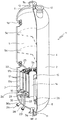
на фиг.1 - схема секции высокого давления предлагаемой в изобретении установки для получения мочевины,figure 1 is a diagram of a section of a high pressure proposed in the invention installation for producing urea,
на фиг.2 - схематичное изображение в увеличенном масштабе реактора синтеза мочевины установки, схема которой показана на фиг.1,figure 2 is a schematic representation on an enlarged scale of the reactor for the synthesis of urea installation, a diagram of which is shown in figure 1,
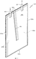
на фиг.3 - увеличенное изображение в аксонометрии теплообменника реактора, показанного на фиг.2,figure 3 is an enlarged image in a perspective view of the heat exchanger of the reactor shown in figure 2,
на фиг.4 и 5 - другие варианты выполнения схематично изображенного в увеличенном масштабе соответственно в аксонометрии и в виде спереди теплообменника, показанного на фиг.3,figure 4 and 5 are other embodiments of schematically depicted on an enlarged scale, respectively, in a perspective view and in front view of the heat exchanger shown in figure 3,
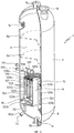
на фиг.6 - другой вариант выполнения схематично изображенного в увеличенном масштабе и показанного на фиг.2 реактора синтеза мочевины предлагаемой в изобретении установки для получения мочевины иin Fig.6 is another variant of execution schematically depicted on an enlarged scale and shown in Fig.2 of the urea synthesis reactor of the installation of the invention for producing urea and
на фиг.7 - увеличенное изображение в аксонометрии теплообменника реактора, показанного на фиг.6.Fig.7 is an enlarged image in a perspective view of the heat exchanger of the reactor shown in Fig.6.
Подробное описание изобретенияDETAILED DESCRIPTION OF THE INVENTION
Показанная на фиг.1 секция высокого давления предназначенной для получения мочевины из аммиака и диоксида углерода установки так называемого "десорбционного типа" состоит по существу из реактора 1 синтеза, десорбера 2 и скруббера 3, которые работают при одном и том же давлении.The high-pressure section shown in FIG. 1 for the urea from ammonia and carbon dioxide of a plant of the so-called "desorption type" consists essentially of a
Внутреннее пространство вертикального корпуса 4 реактора 1 разделено на зону 5 реакции и зону 6 конденсации, в которой расположен подробно описанный выше конденсатор 7.The inner space of the
В зоне 5 реакции расположены перфорированные тарелки 5а обычной конструкции, показанные на фиг.1 пунктирными линиями.In the
Согласно одному, не ограничивающему объем изобретения примеру, при получении мочевины на упомянутой выше установке полученный в реакторе 1 водный раствор, содержащий мочевину, карбамат аммония и свободный аммиак по трубопроводу 1а подают в десорбер 2, в который одновременно снизу по трубопроводу 2b противотоком подают диоксид углерода (весь или часть диоксида углерода, подаваемого на установку).According to one non-limiting example, when producing urea in the aforementioned installation, the aqueous solution obtained in the
Выходящие из десорбера 2 газы, по существу диоксид углерода и аммиак, по трубопроводу 2а подают в реактор 1 под конденсатором 7.The gases leaving the
Раствор, выходящий из десорбера 2, по существу раствор мочевины, карбамата аммония и свободного аммиака, по трубопроводу 2с подают в (не показанную на схеме) секцию выделения мочевины.The
Выходящие из реактора 1 синтеза газы, по существу не вступившие в реакцию аммиак и диоксид углерода и возможно инертные газы, по трубопроводу 1b подают в скруббер 3, в котором очищенные от инертных газов, отбираемых из скруббера по трубопроводу 3с, аммиак и диоксид углерода конденсируют потоком карбамата, который подают в скруббер по трубопроводу 3b из секции выделения мочевины.Gases exiting the
Выходящий из скруббера раствор карбамата вместе с необходимым для проведения реакции аммиаком, добавляемым к раствору карбамата по трубопроводу 3d, подают по трубопроводу 3а в реактор 1 синтеза под конденсатором 7.The carbamate solution exiting the scrubber, together with the ammonia necessary for carrying out the reaction, added to the carbamate solution through the 3d pipeline, is fed through the
Как показано на фиг.2, цилиндрический корпус 4 реактора 1 закрыт с противоположных концов нижним 8 и верхним 9 днищами, при этом в центре нижнего днища 8 расположен патрубок с отверстием 11, предназначенный для подачи в реактор выходящих из десорбера 2 газов (см. ниже) и смеси карбамата аммония, отбираемой из скруббера 3 по трубопроводу 3а. Верхнее днище 9 имеет расположенный в центре патрубок с отверстием 12, через которое из реактора выходят образующиеся в процессе реакции газы, и люк 13, предназначенный для обслуживания реактора.As shown in FIG. 2, the
Конденсатор 7 имеет форму цилиндрического кольца, ось которого совпадает с осью корпуса 4. Наружный диаметр конденсатора несколько меньше внутреннего диаметра корпуса 4, а в центральном отверстии 14 конденсатора расположена съемная труба 15. Труба 15, длина которой больше высоты конденсатора 7, имеет выступающие из конденсатора наружу концы.The
Для установки конденсатора 7 в корпусе реактора предназначен круглый кронштейн 16, закрепленный на внутренней стенке корпуса 4 на определенном расстоянии от его нижнего днища 8.To install the
Предлагаемый в изобретении конденсатор 7 состоит из множества плоских теплообменников 17, которые равномерно расположены концентричными (в данном случае тремя) рядами по окружности конденсатора и каждый из которых (фиг.3) выполнен в виде плоской коробки в форме вытянутого прямоугольника с двумя противоположными длинными сторонами 17а, 17а и двумя противоположными короткими сторонами 17b, 17b.The
В предлагаемом в изобретении конденсаторе 7 теплообменники 17 расположены по существу в радиальных плоскостях с параллельными оси конденсатора 7 (а следовательно, и корпуса 4) длинными сторонами 17а и радиальными короткими сторонами 17b и образуют множество состоящих из трех теплообменников 17 групп, лежащих в разных радиальных плоскостях.In the
Очевидно, что в зависимости от конкретных требований в каждой радиальной плоскости конденсатора можно расположить не три, а два или даже один плоский теплообменник, заполнив при этом теплообменниками по существу полностью все кольцевое пространство между центральной трубой 15 и корпусом 4.Obviously, depending on the specific requirements, in each radial plane of the condenser, it is possible to arrange not three, but two or even one flat heat exchanger, filling with the heat exchangers essentially all of the annular space between the
Каждый теплообменник 17 (фиг.3) состоит из двух уложенных друг на друга и сваренных по периметру металлических листов 18, 19, между которыми остается свободное пространство, образующее внутреннюю полость 21 теплообменника, через которую проходит текучий теплоноситель.Each heat exchanger 17 (Fig. 3) consists of two
На противоположных сторонах каждого теплообменника расположены патрубки 22, 23 соответственно для входа текучего теплоносителя во внутреннюю полость 21 теплообменника и его выхода из нее.On the opposite sides of each heat exchanger there are
В первом варианте осуществления изобретения листы 18, 19, из которых изготовлен теплообменник, соединены друг с другом точечной сваркой во множестве равномерно расположенных предпочтительно по пять в каждом ряду точек 18а, которые придают теплообменнику 17 вид "стеганого полотна". Такой теплообменник, у которого листы соединены между собой точечной сваркой в большом количестве точек 18а, а текучий теплоноситель протекает по извилистой траектории, обладает повышенной эффективностью теплообмена.In a first embodiment of the invention, the
Входные патрубки 22 теплообменников 17 соединены с расположенной в корпусе над конденсатором 7 согнутой по окружности распределительной трубой 24, в которую по выходящей наружу из реактора 1 трубе 25 подают (или выводят) текучий теплоноситель.The
Выходные патрубки 23 теплообменников соединены с расположенным под конденсатором 7 изготовленным из согнутой по окружности трубы коллектором 26, который трубой 27 соединен с патрубком 28 для выхода из реактора 1 (или подачи в него) текучего теплоносителя.The
Под конденсатором 7 расположен закрепленный обычным способом в корпусе реактора изготовленный из согнутой по окружности трубы распределитель 29 газа, соединенный трубой 30 с соответствующим патрубком 30а, который в свою очередь соединен с трубопроводом 2а, по которому в реактор из десорбера 2 подают отбираемые из него газы.Under the
На фиг.4 и 5 показан другой вариант конструкции теплообменника 17, отличающийся от рассмотренного выше варианта более высокой эффективностью теплообмена.Figures 4 and 5 show another design variant of the
В этом варианте каждый теплообменник 117 также изготовлен из двух уложенных друг на друга, но соединенных сваркой только по периметру листов 118, 119 (и поэтому в отличие от описанного выше со ссылкой на фиг.3 теплообменника не имеет вида "стеганого полотна"), образующих на противоположных длинных сторонах 117а теплообменника каналы 31 и 32, один из которых служит распределителем, а другой - коллектором 32 текучего теплоносителя. Каналы 31 и 32 по меньшей мере через одно, предпочтительно через множество отверстий 31 а и 32а, расположенных вдоль одной или нескольких образующих цилиндра, сообщаются с внутренней полостью 121 теплообменника и соединены с патрубками 33 и 34 с выходящими наружу из реактора трубами для подачи в теплообменник 117 и отбора из него текучего теплоносителя.In this embodiment, each
Каналы 31 и 32 можно выполнить на длинных сторонах 117а теплообменника 117 либо сваркой штампованных краев металлических листов 118 и 119, либо из вваренных между листами труб, проходящих параллельно длинным сторонам 117а, 117а теплообменника рядом с краями его внутренней полости 121. Изготовленные из труб каналы имеют выходящие наружу из теплообменника 117 концы, используемые в качестве упомянутых выше патрубков 33 и 34.The
Другой отличительной особенностью выполненного по этому варианту теплообменника является расположение патрубков 33 и 34 для входа и выхода текучего теплоносителя на одной и той же короткой стороне 117b теплообменника.Another distinctive feature of the heat exchanger made according to this embodiment is the location of the
В конденсаторе, показанном на фиг.2, короткие стороны 117b теплообменников с соответствующими патрубками 33 и 34 расположены на верхней стороне каждого теплообменника 117.In the condenser shown in FIG. 2, the
По меньшей мере часть теплообменников 117 предлагаемого в изобретении конденсатора предпочтительно изготовить по схеме, показанной на фиг.5.At least part of the
В изготовленных по этому варианту теплообменниках 117 внутренняя полость разделена на множество не сообщающих непосредственно друг с другом камер 121а, образованных, например, сварными швами 121b, параллельными коротким сторонам 117b теплообменника 117 и соответственно перпендикулярными каналам 31, 32 распределителя и коллектора, которыми сварены между собой металлические листы 118, 119, из которых изготовлен теплообменник. В камерах 121а, которые в зависимости от назначения теплообменника могут иметь одну и ту же или разную ширину, расположены параллельные каналам 31, 32 отражающие пластины 122, формирующие в каждой камере 121а спиральную траекторию движения текучего теплоносителя.In the
Каждая камера 121а соединена, по меньшей мере, одним отверстием 31а с распределителем 31 и, по меньшей мере, одним отверстием 32а с коллектором 32.Each
Необходимо отметить, что для регулирования падения давления, а следовательно, и более равномерного распределения текучего теплоносителя в камерах 121а отверстия 31а в распределителе 31 имеют разную ширину или диаметр, который увеличивается в направлении движения текучего теплоносителя в распределителе 31.It should be noted that in order to control the pressure drop and, consequently, more evenly distribute the fluid coolant in the
На фиг.6 в увеличенном масштабе показан реактор 1 синтеза мочевины, оборудованный конденсатором 107, который в целом аналогичен конденсатору 7, показанному на фиг.2, но состоит из теплообменников 123, которые конструктивно отличаются от теплообменников описанной выше конструкции.FIG. 6 shows, on an enlarged scale, a
Отдельные элементы предлагаемого в этом варианте осуществления изобретения реактора 1, которые конструктивно и функционально не отличаются от аналогичных элементов реактора, показанного на фиг.2, обозначены на чертежах теми же позициями и повторно не рассматриваются.Separate elements of the
Конденсатор 107, предлагаемый в предпочтительном, но не ограничивающем объем изобретения варианте, показанном на фиг.6, состоит из множества равномерно распределенных в трех имеющих общую ось концентричных группах плоских полых теплообменников 123 прямоугольной формы. В конденсаторе 107, показанном на фиг.6, длинные стороны 123а всех теплообменников 123 расположены параллельно оси корпуса 4, а их короткие стороны 123b, 123с направлены радиально к оси корпуса.The
Теплообменники 123 в этом варианте осуществления изобретения предпочтительно выполнить по типу теплообменника, показанного на фиг.3, т.е. теплообменника, изготовленного из двух сваренных между собой по периметру металлических листов с внутренней полостью 125 для прохода текучего теплоносителя.The
Одной из отличительных особенностей этого варианта осуществления изобретения является наличие внутри теплообменника 123 примыкающей к одной из коротких сторон 123с теплообменника перегородки 124, длина которой меньше длины параллельных ей длинных сторон 123а теплообменника.One of the distinguishing features of this embodiment of the invention is the presence inside the
Перегородку 124 предпочтительно выполнить сваркой двух листов, из которых изготовлен теплообменник, по линии, проходящей по середине от одной короткой стороны 123с к другой, противоположной короткой стороне 123b и заканчивающейся на некотором расстоянии от нее.The
Выполненная таким образом перегородка 124 разделяет внутреннюю полость 125 теплообменника 123 на две смежные части 125а, 125b, соединяющиеся друг с другом только у короткой стороны 123b, противоположной короткой стороне 123с, к которой примыкает перегородка.The
Другой отличительной особенностью этого варианта осуществления изобретения является наличие расположенных на короткой стороне 123с теплообменника, к которой примыкает перегородка 124, двух выходящих наружу патрубков 126, 127, соединенных с обеими частями 125а, 125b внутренней полости 125 теплообменника.Another distinctive feature of this embodiment of the invention is the presence of a heat exchanger located on the
В выполненном таким образом теплообменнике 123 разделенная перегородкой на две части 125а, 125b внутренняя полость 125 имеет U-образую форму, и проходящий через нее текучий теплоноситель сначала опускается вниз, а потом поднимается вверх.In the
В конденсаторе 107, предлагаемом в этом варианте осуществления изобретения (фиг.6), расположенные в радиальных плоскостях внутри корпуса 4 теплообменники 123 имеют вертикальные длинные стороны 123а и короткие горизонтальные нижнюю 123b и верхнюю 123с стороны, и расположенные на верхней стороне соединительные патрубки 126 и 127 и крепятся внутри корпуса 4 реактора к кронштейну 16 описанным выше образом.In the
Каждая группа из трех расположенных радиально теплообменников 123 соединена с трубой 128 для распределения подаваемого в них текучего теплоносителя и изготовленным из трубы коллектором 129, в котором собирается выходящий из теплообменников текучий теплоноситель. Труба 128 соединена с патрубками 126 теплообменников 123 трубами 128а, а труба 129 соединена трубами 129а с их другими патрубками 127.Each group of three radially located
Труба 128, через которую в теплообменники подается текучий теплоноситель, выходит наружу через стенку корпуса 4 реактора и соединяется с не показанным на схеме источником текучего теплоносителя (например, кипящей воды).A
Коллектор 129 аналогично трубе 128 для подачи в теплообменники текучего теплоносителя выходит через стенку корпуса 4 реактора наружу и соединяется с различными внешними трубопроводами.The
Для вывода труб 128 и 129 из корпуса 4 реактора наружу предназначены соответствующие соединительные патрубки 130 и 131, расположенные на корпусе на определенной высоте, близкой к высоте расположения верхних сторон 123с отдельных теплообменников 123 или совпадающей с ней.For connecting
Рассмотренный выше вариант обладает еще одним существенным преимуществом. Используемые в этом варианте теплообменники 123 не связаны жестко с другими частями реактора 1, в частности с его корпусом 4, и могут свободно расширяться вверх в вертикальном направлении.The above option has another significant advantage. The
Предлагаемая в изобретении конструкция позволяет избежать проблем механического характера, связанных с разным тепловым расширением теплообменников и корпуса реактора. Такие проблемы обычно возникают в тех случаях, когда протекающий внутри теплообменников текучий теплоноситель отличается от обтекающей теплообменники снаружи текучей среды.The design proposed in the invention avoids mechanical problems associated with different thermal expansion of the heat exchangers and the reactor vessel. Such problems usually arise in cases where the fluid flowing inside the heat exchangers differs from the fluid flowing around the heat exchangers on the outside.
На фиг.7 показан еще один вариант конструкции теплообменника 123, который предназначен главным образом при использовании воды в качестве протекающего через теплообменники текучего теплоносителя. В соответствии с этим вариантом расположенная во внутренней полости 125 теплообменника перегородка 124 наклонена под углом к примыкающей к ней стороне 123с теплообменника 123 (т.е. под углом к его длинным сторонам) и образует внутри теплообменника U-образную внутреннюю полость 125 с опускающимся, а затем поднимающимся вверх участками, которые имеют в направлении течения текучего теплоносителя постепенно возрастающую площадь поперечного сечения.7 shows another design variant of the
Размеры поперечного сечения теплообменников 17, 117 и 123 выбирают с учетом того, чтобы каждый теплообменник мог свободно пройти через расположенный на корпусе реактора 1 люк 13.The cross-sectional dimensions of the
Преимущества настоящего изобретения можно в итоге сформулировать следующим образом:The advantages of the present invention can be summarized as follows:
- возможность создания установки для получения мочевины с существенно большей по сравнению с известными установками подобного типа производительностью, достигаемой за счет того, что наиболее важный с этой точки зрения аппарат, в частности конденсатор, в предлагаемой в изобретении установке не имеет никаких ограничивающих производительность установки трубных решеток;- the possibility of creating a plant for the production of urea with a significantly higher productivity compared to known plants of this type, achieved due to the fact that the apparatus most important from this point of view, in particular the condenser, in the apparatus proposed in the invention does not limit the performance of the installation of tube sheets ;
- отсутствие проблемы, связанной с неравномерным распределением раствора мочевины и карбамата по трубам трубных пучков и негарантированным эффективным нагревом или охлаждением труб обтекающей их снаружи текучей средой;- the absence of a problem associated with the uneven distribution of the urea and carbamate solution among the tube bundle pipes and the unwarranted effective heating or cooling of the tubes by the fluid flowing around them from the outside;
- возможность устранения недостатков механического характера, связанных с разным тепловым расширением теплообменников и корпуса реактора;- the ability to eliminate mechanical deficiencies associated with different thermal expansion of heat exchangers and the reactor vessel;
- возможность легкого и быстрого определения и замены поврежденных пластин или групп теплообменников;- the ability to easily and quickly identify and replace damaged plates or groups of heat exchangers;
- легкость и быстрота монтажа конденсатора внутри соответствующего корпуса, обусловленная небольшим размерами теплообменников, выбранных с учетом их прохождения через обычно расположенный на корпусе реактора люк;- ease and speed of installation of the condenser inside the corresponding vessel, due to the small size of the heat exchangers selected taking into account their passage through the hatch usually located on the reactor vessel;
- снижение капитальных затрат и возможность создания установки более простым и более дешевым по сравнению с известными установками способом.- reduction in capital costs and the ability to create a plant in a simpler and cheaper way compared to known installations.
Изобретение не исключает возможности внесения в рассмотренные выше варианты его осуществления различных очевидных для специалистов изменений и усовершенствований, не искажающих смысла и не выходящих за объем изобретения, определяемый его формулой.The invention does not exclude the possibility of introducing into the above variants of its implementation various obvious changes for specialists and improvements that do not distort the meaning and do not go beyond the scope of the invention defined by its formula.
Claims (15)
Applications Claiming Priority (2)
| Application Number | Priority Date | Filing Date | Title |
|---|---|---|---|
| EP02014473.9 | 2002-06-28 | ||
| EP02014473A EP1375475A1 (en) | 2002-06-28 | 2002-06-28 | Plant for urea production |
Publications (2)
| Publication Number | Publication Date |
|---|---|
| RU2005102067A RU2005102067A (en) | 2006-04-20 |
| RU2296748C2 true RU2296748C2 (en) | 2007-04-10 |
Family
ID=29716875
Family Applications (1)
| Application Number | Title | Priority Date | Filing Date |
|---|---|---|---|
| RU2005102067/04A RU2296748C2 (en) | 2002-06-28 | 2003-06-04 | Urea producing apparatus |
Country Status (13)
| Country | Link |
|---|---|
| US (2) | US20060099118A1 (en) |
| EP (2) | EP1375475A1 (en) |
| CN (1) | CN1289474C (en) |
| AR (1) | AR039759A1 (en) |
| AT (1) | ATE394368T1 (en) |
| AU (1) | AU2003245908B2 (en) |
| BR (1) | BR0312084B1 (en) |
| CA (1) | CA2486534C (en) |
| DE (1) | DE60320801D1 (en) |
| EG (1) | EG24556A (en) |
| MY (1) | MY136425A (en) |
| RU (1) | RU2296748C2 (en) |
| WO (1) | WO2004002949A1 (en) |
Cited By (2)
| Publication number | Priority date | Publication date | Assignee | Title |
|---|---|---|---|---|
| RU2720083C2 (en) * | 2015-08-25 | 2020-04-24 | Касале Са | Reactor-condenser for synthesis of urea |
| RU2729068C2 (en) * | 2016-03-17 | 2020-08-04 | Касале Са | Combined device for high pressure urea synthesis |
Families Citing this family (8)
| Publication number | Priority date | Publication date | Assignee | Title |
|---|---|---|---|---|
| US7093649B2 (en) * | 2004-02-10 | 2006-08-22 | Peter Dawson | Flat heat exchanger plate and bulk material heat exchanger using the same |
| DE102004050365A1 (en) * | 2004-10-15 | 2006-04-27 | BSH Bosch und Siemens Hausgeräte GmbH | beverage maker |
| EP1782883A1 (en) * | 2005-11-08 | 2007-05-09 | Methanol Casale S.A. | Isothermal chemical reactor |
| US9528772B2 (en) * | 2008-01-28 | 2016-12-27 | Freimut Joachim Marold | Multi-passage thermal sheet and heat exchanger equipped therewith |
| EP2705285B1 (en) | 2011-06-27 | 2014-08-27 | Tongaat Hulett Limited | Rotary distribution apparatus |
| EP2818821B1 (en) * | 2013-06-27 | 2016-02-03 | Linde Aktiengesellschaft | Coiled heat exchanger with core tube feed |
| EA034482B1 (en) * | 2013-12-17 | 2020-02-12 | Стамикарбон Б.В. | Integrated production of urea and melamine |
| JP7209874B2 (en) | 2019-06-07 | 2023-01-20 | スタミカーボン・ベー・フェー | Urea plant with stripper and stripping method |
Family Cites Families (11)
| Publication number | Priority date | Publication date | Assignee | Title |
|---|---|---|---|---|
| US888169A (en) * | 1907-07-01 | 1908-05-19 | Victor Haehl & Cie | Heating or cooling apparatus. |
| US3294082A (en) * | 1964-08-19 | 1966-12-27 | Lennox Ind Inc | Serpentine-type heat exchange assembly |
| US3512239A (en) * | 1967-04-19 | 1970-05-19 | Rosenblad Corp | Method of forming dimpled plate heat exchanger elements by the use of hydrostatic pressure |
| US4519446A (en) * | 1983-03-31 | 1985-05-28 | Kamyr, Inc. | Surface condenser/water heating |
| DE4300131C2 (en) * | 1993-01-06 | 1999-08-05 | Hoechst Ag | Column with integrated heat exchanger |
| NL1011123C2 (en) * | 1999-01-25 | 2000-07-27 | Dsm Nv | Process for the preparation of urea. |
| JP4312339B2 (en) * | 2000-02-24 | 2009-08-12 | ナブテスコ株式会社 | Heat transfer device with meandering passage |
| EP1153653A1 (en) * | 2000-05-11 | 2001-11-14 | Methanol Casale S.A. | Reactor for exothermic or endothermic heterogeneous reactions |
| JP4191879B2 (en) * | 2000-07-04 | 2008-12-03 | 東洋エンジニアリング株式会社 | Urea synthesis method and apparatus |
| EP1221339A1 (en) * | 2001-01-05 | 2002-07-10 | Methanol Casale S.A. | Catalytic reactor with heat exchanger for exothermic and endothermic heterogeneous chemical reactions |
| NL1017990C2 (en) * | 2001-05-03 | 2002-11-05 | Dsm Nv | Process for the preparation of urea. |
-
2002
- 2002-06-28 EP EP02014473A patent/EP1375475A1/en not_active Withdrawn
-
2003
- 2003-06-04 AU AU2003245908A patent/AU2003245908B2/en not_active Expired
- 2003-06-04 WO PCT/EP2003/005839 patent/WO2004002949A1/en active IP Right Grant
- 2003-06-04 CN CNB038152800A patent/CN1289474C/en not_active Expired - Lifetime
- 2003-06-04 EP EP03737989A patent/EP1530563B1/en not_active Expired - Lifetime
- 2003-06-04 US US10/519,742 patent/US20060099118A1/en not_active Abandoned
- 2003-06-04 BR BRPI0312084-8A patent/BR0312084B1/en active IP Right Grant
- 2003-06-04 CA CA2486534A patent/CA2486534C/en not_active Expired - Lifetime
- 2003-06-04 DE DE60320801T patent/DE60320801D1/en not_active Expired - Lifetime
- 2003-06-04 AT AT03737989T patent/ATE394368T1/en not_active IP Right Cessation
- 2003-06-04 RU RU2005102067/04A patent/RU2296748C2/en active
- 2003-06-11 MY MYPI20032172A patent/MY136425A/en unknown
- 2003-06-23 EG EG2003060600A patent/EG24556A/en active
- 2003-06-26 AR ARP030102307A patent/AR039759A1/en unknown
-
2009
- 2009-02-06 US US12/367,240 patent/US8721975B2/en not_active Expired - Lifetime
Cited By (2)
| Publication number | Priority date | Publication date | Assignee | Title |
|---|---|---|---|---|
| RU2720083C2 (en) * | 2015-08-25 | 2020-04-24 | Касале Са | Reactor-condenser for synthesis of urea |
| RU2729068C2 (en) * | 2016-03-17 | 2020-08-04 | Касале Са | Combined device for high pressure urea synthesis |
Also Published As
| Publication number | Publication date |
|---|---|
| EP1530563B1 (en) | 2008-05-07 |
| CN1289474C (en) | 2006-12-13 |
| US8721975B2 (en) | 2014-05-13 |
| AU2003245908B2 (en) | 2009-06-04 |
| EP1530563A1 (en) | 2005-05-18 |
| BR0312084A (en) | 2005-03-22 |
| US20090220396A1 (en) | 2009-09-03 |
| AU2003245908A1 (en) | 2004-01-19 |
| CN1665777A (en) | 2005-09-07 |
| EG24556A (en) | 2009-10-12 |
| MY136425A (en) | 2008-09-30 |
| EP1375475A1 (en) | 2004-01-02 |
| RU2005102067A (en) | 2006-04-20 |
| CA2486534A1 (en) | 2004-01-08 |
| DE60320801D1 (en) | 2008-06-19 |
| CA2486534C (en) | 2011-08-09 |
| BR0312084B1 (en) | 2013-03-19 |
| ATE394368T1 (en) | 2008-05-15 |
| WO2004002949A1 (en) | 2004-01-08 |
| US20060099118A1 (en) | 2006-05-11 |
| AR039759A1 (en) | 2005-03-09 |
Similar Documents
| Publication | Publication Date | Title |
|---|---|---|
| JP4651889B2 (en) | Isothermal reactor for exothermic or endothermic heterogeneous reactions | |
| US6916453B2 (en) | Reactor for exothermic or endothermic heterogeneous reactions | |
| US8721975B2 (en) | Plant for urea production | |
| AU2001265917A1 (en) | Reactor for exothermic or endothermic heterogeneous reactions | |
| US6444180B1 (en) | Reactor for two-phase reactions, in particular for urea synthesis at high pressure and temperature | |
| RU2346734C2 (en) | Chemical reactor | |
| CH666198A5 (en) | REACTOR FOR CATALYTIC SYNTHESIS OF AMMONIA, METHANOL AND HIGHER ALCOHOLS. | |
| EP2473267B1 (en) | Vertical isothermal shell-and-tube reactor and use thereof for methanol synthesis | |
| US7204301B2 (en) | Multiservice heat exchange unit | |
| RU2310641C2 (en) | Method and installation for the heterogeneous synthesis of methanol or ammonia | |
| EP2359921A1 (en) | Falling-film stripper and stripping medium distributor for carbamate decomposition | |
| RU2746734C1 (en) | Multilayer catalytic converter with interlayer cooling | |
| US9120068B2 (en) | Isothermal chemical reactor with plate heat exchanger | |
| CN105903413A (en) | Gas-gas heat exchange type isothermal reactor | |
| US7981271B2 (en) | Pseudo-isothermal radial reactor | |
| EP1469269A1 (en) | Method to increase the potential of a falling film tube bundle heat exchanger | |
| JPH0438734B2 (en) | ||
| RU2803814C2 (en) | High pressure stripper columns for use in urea plants | |
| RU2341750C1 (en) | Heat exchanger | |
| SU674783A1 (en) | Ammonia synthesis column |