RU2295477C2 - Container sealing devices - Google Patents
Container sealing devices Download PDFInfo
- Publication number
- RU2295477C2 RU2295477C2 RU2004123255/12A RU2004123255A RU2295477C2 RU 2295477 C2 RU2295477 C2 RU 2295477C2 RU 2004123255/12 A RU2004123255/12 A RU 2004123255/12A RU 2004123255 A RU2004123255 A RU 2004123255A RU 2295477 C2 RU2295477 C2 RU 2295477C2
- Authority
- RU
- Russia
- Prior art keywords
- neck
- foil
- side wall
- container
- plastic
- Prior art date
Links
- 238000007789 sealing Methods 0.000 title abstract description 13
- 239000011888 foil Substances 0.000 claims abstract description 59
- 229920003023 plastic Polymers 0.000 claims abstract description 43
- 239000004033 plastic Substances 0.000 claims abstract description 43
- 229920000139 polyethylene terephthalate Polymers 0.000 claims abstract description 33
- 239000005020 polyethylene terephthalate Substances 0.000 claims abstract description 33
- 238000000034 method Methods 0.000 claims abstract description 25
- -1 polyethylene terephthalate Polymers 0.000 claims abstract description 9
- 239000000463 material Substances 0.000 claims description 30
- 239000011248 coating agent Substances 0.000 claims description 8
- 238000000576 coating method Methods 0.000 claims description 8
- 238000003466 welding Methods 0.000 claims description 8
- 230000004888 barrier function Effects 0.000 claims description 4
- 239000004743 Polypropylene Substances 0.000 claims description 3
- 229920001155 polypropylene Polymers 0.000 claims description 3
- 229920000915 polyvinyl chloride Polymers 0.000 claims description 3
- 239000004800 polyvinyl chloride Substances 0.000 claims description 3
- 238000010008 shearing Methods 0.000 claims description 3
- 239000004698 Polyethylene Substances 0.000 claims description 2
- 238000009434 installation Methods 0.000 claims description 2
- 229920000573 polyethylene Polymers 0.000 claims description 2
- 150000001875 compounds Chemical class 0.000 claims 1
- 238000011089 mechanical engineering Methods 0.000 abstract 1
- 230000002265 prevention Effects 0.000 abstract 1
- 239000000126 substance Substances 0.000 abstract 1
- 210000003739 neck Anatomy 0.000 description 88
- 238000005516 engineering process Methods 0.000 description 13
- 238000000071 blow moulding Methods 0.000 description 5
- 238000001746 injection moulding Methods 0.000 description 5
- 239000002131 composite material Substances 0.000 description 4
- 239000006223 plastic coating Substances 0.000 description 4
- 238000002425 crystallisation Methods 0.000 description 3
- 230000008025 crystallization Effects 0.000 description 3
- 238000002347 injection Methods 0.000 description 3
- 239000007924 injection Substances 0.000 description 3
- 238000004806 packaging method and process Methods 0.000 description 3
- 239000000243 solution Substances 0.000 description 3
- 241000894006 Bacteria Species 0.000 description 2
- 229920000219 Ethylene vinyl alcohol Polymers 0.000 description 2
- MHAJPDPJQMAIIY-UHFFFAOYSA-N Hydrogen peroxide Chemical compound OO MHAJPDPJQMAIIY-UHFFFAOYSA-N 0.000 description 2
- 239000004594 Masterbatch (MB) Substances 0.000 description 2
- 208000035415 Reinfection Diseases 0.000 description 2
- 229910000831 Steel Inorganic materials 0.000 description 2
- 229910052782 aluminium Inorganic materials 0.000 description 2
- XAGFODPZIPBFFR-UHFFFAOYSA-N aluminium Chemical compound [Al] XAGFODPZIPBFFR-UHFFFAOYSA-N 0.000 description 2
- 230000015572 biosynthetic process Effects 0.000 description 2
- 238000001816 cooling Methods 0.000 description 2
- UFRKOOWSQGXVKV-UHFFFAOYSA-N ethene;ethenol Chemical compound C=C.OC=C UFRKOOWSQGXVKV-UHFFFAOYSA-N 0.000 description 2
- 239000004715 ethylene vinyl alcohol Substances 0.000 description 2
- 238000005755 formation reaction Methods 0.000 description 2
- 239000008187 granular material Substances 0.000 description 2
- 229920001903 high density polyethylene Polymers 0.000 description 2
- 239000004700 high-density polyethylene Substances 0.000 description 2
- 238000002844 melting Methods 0.000 description 2
- 230000008018 melting Effects 0.000 description 2
- 239000010959 steel Substances 0.000 description 2
- 239000002253 acid Substances 0.000 description 1
- 239000012080 ambient air Substances 0.000 description 1
- 238000009924 canning Methods 0.000 description 1
- 238000005266 casting Methods 0.000 description 1
- 238000004821 distillation Methods 0.000 description 1
- 239000007789 gas Substances 0.000 description 1
- 239000011521 glass Substances 0.000 description 1
- 238000010438 heat treatment Methods 0.000 description 1
- 230000006698 induction Effects 0.000 description 1
- 238000009413 insulation Methods 0.000 description 1
- 238000004519 manufacturing process Methods 0.000 description 1
- 239000000155 melt Substances 0.000 description 1
- 229910052751 metal Inorganic materials 0.000 description 1
- 239000002184 metal Substances 0.000 description 1
- 239000000123 paper Substances 0.000 description 1
- 238000009928 pasteurization Methods 0.000 description 1
- 230000035515 penetration Effects 0.000 description 1
- 230000002035 prolonged effect Effects 0.000 description 1
- 230000003014 reinforcing effect Effects 0.000 description 1
- 229910000679 solder Inorganic materials 0.000 description 1
- 230000001954 sterilising effect Effects 0.000 description 1
- 238000004659 sterilization and disinfection Methods 0.000 description 1
Images

Classifications
-
- B—PERFORMING OPERATIONS; TRANSPORTING
- B65—CONVEYING; PACKING; STORING; HANDLING THIN OR FILAMENTARY MATERIAL
- B65D—CONTAINERS FOR STORAGE OR TRANSPORT OF ARTICLES OR MATERIALS, e.g. BAGS, BARRELS, BOTTLES, BOXES, CANS, CARTONS, CRATES, DRUMS, JARS, TANKS, HOPPERS, FORWARDING CONTAINERS; ACCESSORIES, CLOSURES, OR FITTINGS THEREFOR; PACKAGING ELEMENTS; PACKAGES
- B65D51/00—Closures not otherwise provided for
- B65D51/18—Arrangements of closures with protective outer cap-like covers or of two or more co-operating closures
- B65D51/20—Caps, lids, or covers co-operating with an inner closure arranged to be opened by piercing, cutting, or tearing
-
- B—PERFORMING OPERATIONS; TRANSPORTING
- B65—CONVEYING; PACKING; STORING; HANDLING THIN OR FILAMENTARY MATERIAL
- B65B—MACHINES, APPARATUS OR DEVICES FOR, OR METHODS OF, PACKAGING ARTICLES OR MATERIALS; UNPACKING
- B65B7/00—Closing containers or receptacles after filling
- B65B7/16—Closing semi-rigid or rigid containers or receptacles not deformed by, or not taking-up shape of, contents, e.g. boxes or cartons
- B65B7/28—Closing semi-rigid or rigid containers or receptacles not deformed by, or not taking-up shape of, contents, e.g. boxes or cartons by applying separate preformed closures, e.g. lids, covers
- B65B7/2842—Securing closures on containers
- B65B7/285—Securing closures on containers by deformation of the closure
-
- B—PERFORMING OPERATIONS; TRANSPORTING
- B65—CONVEYING; PACKING; STORING; HANDLING THIN OR FILAMENTARY MATERIAL
- B65B—MACHINES, APPARATUS OR DEVICES FOR, OR METHODS OF, PACKAGING ARTICLES OR MATERIALS; UNPACKING
- B65B7/00—Closing containers or receptacles after filling
- B65B7/16—Closing semi-rigid or rigid containers or receptacles not deformed by, or not taking-up shape of, contents, e.g. boxes or cartons
- B65B7/28—Closing semi-rigid or rigid containers or receptacles not deformed by, or not taking-up shape of, contents, e.g. boxes or cartons by applying separate preformed closures, e.g. lids, covers
- B65B7/2842—Securing closures on containers
- B65B7/2878—Securing closures on containers by heat-sealing
-
- B—PERFORMING OPERATIONS; TRANSPORTING
- B65—CONVEYING; PACKING; STORING; HANDLING THIN OR FILAMENTARY MATERIAL
- B65D—CONTAINERS FOR STORAGE OR TRANSPORT OF ARTICLES OR MATERIALS, e.g. BAGS, BARRELS, BOTTLES, BOXES, CANS, CARTONS, CRATES, DRUMS, JARS, TANKS, HOPPERS, FORWARDING CONTAINERS; ACCESSORIES, CLOSURES, OR FITTINGS THEREFOR; PACKAGING ELEMENTS; PACKAGES
- B65D47/00—Closures with filling and discharging, or with discharging, devices
- B65D47/04—Closures with discharging devices other than pumps
- B65D47/06—Closures with discharging devices other than pumps with pouring spouts or tubes; with discharge nozzles or passages
- B65D47/10—Closures with discharging devices other than pumps with pouring spouts or tubes; with discharge nozzles or passages having frangible closures
- B65D47/103—Membranes with a tearing element
-
- B—PERFORMING OPERATIONS; TRANSPORTING
- B29—WORKING OF PLASTICS; WORKING OF SUBSTANCES IN A PLASTIC STATE IN GENERAL
- B29C—SHAPING OR JOINING OF PLASTICS; SHAPING OF MATERIAL IN A PLASTIC STATE, NOT OTHERWISE PROVIDED FOR; AFTER-TREATMENT OF THE SHAPED PRODUCTS, e.g. REPAIRING
- B29C65/00—Joining or sealing of preformed parts, e.g. welding of plastics materials; Apparatus therefor
- B29C65/02—Joining or sealing of preformed parts, e.g. welding of plastics materials; Apparatus therefor by heating, with or without pressure
-
- B—PERFORMING OPERATIONS; TRANSPORTING
- B29—WORKING OF PLASTICS; WORKING OF SUBSTANCES IN A PLASTIC STATE IN GENERAL
- B29C—SHAPING OR JOINING OF PLASTICS; SHAPING OF MATERIAL IN A PLASTIC STATE, NOT OTHERWISE PROVIDED FOR; AFTER-TREATMENT OF THE SHAPED PRODUCTS, e.g. REPAIRING
- B29C66/00—General aspects of processes or apparatus for joining preformed parts
- B29C66/50—General aspects of joining tubular articles; General aspects of joining long products, i.e. bars or profiled elements; General aspects of joining single elements to tubular articles, hollow articles or bars; General aspects of joining several hollow-preforms to form hollow or tubular articles
- B29C66/51—Joining tubular articles, profiled elements or bars; Joining single elements to tubular articles, hollow articles or bars; Joining several hollow-preforms to form hollow or tubular articles
- B29C66/54—Joining several hollow-preforms, e.g. half-shells, to form hollow articles, e.g. for making balls, containers; Joining several hollow-preforms, e.g. half-cylinders, to form tubular articles
- B29C66/542—Joining several hollow-preforms, e.g. half-shells, to form hollow articles, e.g. for making balls, containers; Joining several hollow-preforms, e.g. half-cylinders, to form tubular articles joining hollow covers or hollow bottoms to open ends of container bodies
-
- B—PERFORMING OPERATIONS; TRANSPORTING
- B29—WORKING OF PLASTICS; WORKING OF SUBSTANCES IN A PLASTIC STATE IN GENERAL
- B29L—INDEXING SCHEME ASSOCIATED WITH SUBCLASS B29C, RELATING TO PARTICULAR ARTICLES
- B29L2031/00—Other particular articles
- B29L2031/56—Stoppers or lids for bottles, jars, or the like, e.g. closures
- B29L2031/565—Stoppers or lids for bottles, jars, or the like, e.g. closures for containers
-
- Y—GENERAL TAGGING OF NEW TECHNOLOGICAL DEVELOPMENTS; GENERAL TAGGING OF CROSS-SECTIONAL TECHNOLOGIES SPANNING OVER SEVERAL SECTIONS OF THE IPC; TECHNICAL SUBJECTS COVERED BY FORMER USPC CROSS-REFERENCE ART COLLECTIONS [XRACs] AND DIGESTS
- Y10—TECHNICAL SUBJECTS COVERED BY FORMER USPC
- Y10T—TECHNICAL SUBJECTS COVERED BY FORMER US CLASSIFICATION
- Y10T29/00—Metal working
- Y10T29/49—Method of mechanical manufacture
- Y10T29/49826—Assembling or joining
- Y10T29/49904—Assembling a subassembly, then assembling with a second subassembly
Landscapes
- Mechanical Engineering (AREA)
- Engineering & Computer Science (AREA)
- Closures For Containers (AREA)
- Glass Compositions (AREA)
- Cartons (AREA)
- Containers Opened By Tearing Frangible Portions (AREA)
- Details Of Rigid Or Semi-Rigid Containers (AREA)
- Closing Of Containers (AREA)
- Containers Having Bodies Formed In One Piece (AREA)
- Rigid Containers With Two Or More Constituent Elements (AREA)
- Seal Device For Vehicle (AREA)
- Tubes (AREA)
- Packages (AREA)
Abstract
Description
Предпосылки к созданию изобретенияBACKGROUND OF THE INVENTION
Настоящее изобретение имеет отношение к технологии укупорки для пластмассовых или имеющих пластмассовое покрытие контейнеров. Оно может быть применено к пластмассовым бутылкам и стальным контейнерам, которые имеют пластмассовое покрытие, или к контейнерам, изготовленным из композиционных материалов слоистой конструкции, имеющим пластмассовые поверхности со слоями из бумаги и EVOH или с алюминиевыми слоями, склеенными вместе между пластмассовыми поверхностями.The present invention relates to closure technology for plastic or plastic coated containers. It can be applied to plastic bottles and steel containers that have a plastic coating, or to containers made of composite materials with a layered structure, having plastic surfaces with layers of paper and EVOH or with aluminum layers glued together between plastic surfaces.
Настоящее изобретение особенно хорошо подходит для сатурированных (газированных) и несатурированных, пастеризованных, асептических продуктов или продуктов горячей заливки, а более конкретно, имеет отношение к способу сборки пластмассовой горловины с таким контейнером. Преобладающим пластмассовым материалом для газонепроницаемых и теплостойких пластмассовых бутылок, подходящих для такого применения, является PET (полиэтилентерефталат).The present invention is particularly well suited for carbonated (carbonated) and unsaturated, pasteurized, aseptic or hot-fill products, and more particularly, relates to a method for assembling a plastic neck with such a container. The predominant plastic material for gas-tight and heat-resistant plastic bottles suitable for such an application is PET (polyethylene terephthalate).
PET бутылки (бутылки из полиэтилентерефталата) не могут быть использованы для стерилизации путем дистилляции или автоклавной обработки, которую используют для консервных банок, стеклянных бутылок и некоторых имеющих высокую теплостойкость пластмасс, таких как полипропилен, так как эти бутылки не могут выдерживать длительное воздействие соответствующих температур порядка 120°С.PET bottles (polyethylene terephthalate bottles) cannot be used for sterilization by distillation or autoclaving, which is used for cans, glass bottles and some highly heat-resistant plastics, such as polypropylene, since these bottles cannot withstand prolonged exposure to appropriate temperatures of the order of 120 ° C.
Однако стерильное упаковывание в такие пластмассовые бутылки может быть обеспечено при помощи асептического процесса или за счет горячей заливки.However, sterile packaging in such plastic bottles can be achieved by aseptic process or by hot pouring.
При асептической заливке используют процесс пастеризации для обработки продукта перед заливкой. Продукт подвергают воздействию высокой температуры (140°С) в течение очень короткого промежутка времени (4 секунды) и затем охлаждают до температуры в диапазоне от температуры окружающей среды до 4°С. После охлаждения продукт должен оставаться в стерильных условиях и не должен подвергаться воздействию окружающего воздуха или бактерий. Бутылки и крышки также должны быть очищены и стерилизованы, обычно с использованием перекиси водорода или паруксусной кислоты, испаряющей свои компоненты. Бутылки затем заполняют и укупоривают в асептической среде. Укупорка должна быть достаточно плотной (герметичной), чтобы предотвратить повторную инфекцию. В то время как этот способ является эффективным для обеспечения длительного срока годности при хранении и может быть использован для PET бутылок, следует иметь в виду, что стоимость такой установки для розлива является существенной.In aseptic pouring, the pasteurization process is used to process the product before pouring. The product is exposed to high temperature (140 ° C) for a very short period of time (4 seconds) and then cooled to a temperature in the range from ambient temperature to 4 ° C. After cooling, the product must remain under sterile conditions and must not be exposed to ambient air or bacteria. Bottles and caps should also be cleaned and sterilized, usually using hydrogen peroxide or paraacetic acid, which evaporates its components. The bottles are then filled and sealed in an aseptic environment. The closure should be tight enough to prevent reinfection. While this method is effective for providing a long shelf life and can be used for PET bottles, it should be borne in mind that the cost of such a bottling plant is substantial.
PET бутылки также используют в процессах горячей заливки (заполнения), в которых продукт при температуре обычно свыше 85°С вводят в бутылку. В этом процессе бутылки должны быть чистыми, но не обязательно стерильными, так как любые присутствующие бактерии в горячем продукте будут убиты. Процессы горячей заливки являются более экономически выгодными, однако их применение ограничено за счет ограниченной термостойкости PET, который испытывает коробление при температурах свыше 75°С. Следует иметь в виду, что повышенная термостойкость может быть достигнута за счет кристаллизации горлышка (шейки) бутылки, однако это приводит к повышению стоимости упаковывания.PET bottles are also used in hot filling (filling) processes, in which the product is usually introduced into the bottle at temperatures above 85 ° C. In this process, the bottles should be clean, but not necessarily sterile, as any bacteria present in the hot product will be killed. Hot pouring processes are more cost-effective, but their use is limited due to the limited heat resistance of PET, which experiences warpage at temperatures above 75 ° C. It should be borne in mind that increased heat resistance can be achieved by crystallization of the neck (neck) of the bottle, however, this leads to an increase in packaging costs.
Другой технической проблемой, с которой сталкиваются, когда PET бутылки используют при горячей заливке, является создание парциального вакуума внутри бутылки после ее герметизации, когда продукт охлаждается. Это заставляет создавать конструкции, которые не позволяют контейнеру сплющиваться. Примеры таких конструкций описаны в публикациях WO 0113407 и WO 0112531.Another technical problem encountered when PET bottles are used for hot pouring is the creation of a partial vacuum inside the bottle after it is sealed when the product cools. This forces the creation of structures that do not allow the container to flatten. Examples of such structures are described in publications WO 0113407 and WO 0112531.
Полученная путем формования с раздувом и вытяжкой PET бутылка обычно может быть укупорена (герметизирована) при помощи полученной за счет литьевого формования крышки, которую надевают на полученные при помощи литьевого формования элементы на горлышке заготовки, ранее проведения формования с раздувом и вытяжкой, чтобы получить бутылку. Это позволяет получить хорошие характеристики герметизации, если горлышко сохраняет первоначальную форму, однако эти характеристики падают, если происходит деформация в ходе процесса горячей заливки. Таким образом, герметичное уплотнение является основным условием для предотвращения повторной инфекции, которая ограничивает диапазон использования PET бутылок в более экономически выгодном процессе горячей заливки, несмотря на то, что эта проблема может быть решена за счет использования горлышка, которое содержит больший объем материала, или за счет кристаллизации. Однако эти решения повышают стоимость упаковывания. Задачей настоящего изобретения является решение этой технической проблемы за счет использования альтернативной технологии укупорки.The PET bottle obtained by blow-molding can usually be sealed (sealed) by means of a cap obtained by injection molding, which is put on the elements obtained by injection molding on the neck of a workpiece, previously carried out by blow-molding and drawing to obtain a bottle. This allows to obtain good sealing characteristics if the neck retains its original shape, however, these characteristics drop if deformation occurs during the hot pouring process. Thus, a tight seal is the main condition for preventing re-infection, which limits the range of use of PET bottles in a more cost-effective hot pouring process, although this problem can be solved by using a neck that contains a larger volume of material, or crystallization account. However, these solutions add to the cost of packaging. An object of the present invention is to solve this technical problem by using alternative capping technology.
Полученная при помощи литьевого формования горловина с крышкой описана в публикации WO 99/61337. Этот тип технологии укупорки был применен для формованных при помощи экструзии с раздувом бутылок, когда корпус бутылки, горловина и крышка могут быть сделаны из одного и того же материала, обычно из полиэтилена высокой плотности (HDPE). Такой материал обычно имеет температуру плавления 140°С. При использовании этой технологии укупорки бутылку и горловину герметично соединяют друг с другом при помощи промежуточной покрытой пластмассой фольги, которую приваривают к обеим поверхностям. Горловину и узел крышки соединяют с корпусом бутылки после заполнения, поэтому они не подвергаются воздействию заливаемого продукта в ходе горячей заливки. Следует иметь в виду, что возникают технические проблемы, если такой узел укупорки применяют для PET бутылки.An injection cap with a cap is described in WO 99/61337. This type of capping technology has been applied to blow molded bottles where the bottle body, neck and cap can be made of the same material, usually high density polyethylene (HDPE). Such a material typically has a melting point of 140 ° C. Using this capping technology, the bottle and neck are sealed to each other using an intermediate plastic-coated foil that is welded to both surfaces. The neck and cap assembly are connected to the bottle body after filling, so they are not exposed to the product being poured during hot filling. It should be borne in mind that technical problems arise if such a closure assembly is used for PET bottles.
Первая техническая проблема связана с короблением заливочной части (воронки) горловины, когда она подвергается воздействию температур, достаточных для осуществления сварки фольги с PET, который плавится только при 220°С, хотя некоторое коробление может происходить и при более низких температурах. Обычно горловину не делают из PET, так как этот материал является слишком хрупким для изготовления при помощи литьевого формования компонента такого типа.The first technical problem is related to warpage of the filling part (funnel) of the neck when it is exposed to temperatures sufficient to weld the foil with PET, which melts only at 220 ° C, although some warping can occur at lower temperatures. Typically, the neck is not made of PET, as this material is too brittle for injection molding of a component of this type.
Вторая техническая проблема, связанная с низкой прочностью сварного шва, возникает в том случае, когда используют низкие температуры для получения сварного соединения между покрытой пластмассой фольгой и PET бутылкой. Это может приводить к получению сварного соединения, которое не является достаточно прочным для того, чтобы выдерживать давление газированного продукта. Если сварное соединение между горловиной и корпусом бутылки является слабым, то можно удалить горловину в этом соединении за счет введения рычага под юбку горловины и использования кольца для транспортировки бутылки в качестве опоры для поворота рычага. Это подрывает использование фольги в качестве свидетельства несанкционированного обращения.A second technical problem associated with the low strength of the weld arises when low temperatures are used to produce a weld between the plastic coated foil and the PET bottle. This may result in a weld that is not strong enough to withstand the pressure of the carbonated product. If the welded connection between the neck and the bottle body is weak, you can remove the neck in this connection by introducing a lever under the neck skirt and using the ring to transport the bottle as a support for turning the lever. This undermines the use of foil as evidence of unauthorized handling.
Известные технические предложения, которые описаны в патенте GB-A-2108464, касаются приварки фольги на верхней плоской поверхности контейнера. Однако это предложение создает третью техническую проблему при использовании PET контейнеров, связанную с низкой прочностью сварного соединения, как уже было описано здесь ранее.Known technical proposals, which are described in patent GB-A-2108464, relate to the welding of foil on the upper flat surface of the container. However, this proposal poses a third technical problem with the use of PET containers associated with the low strength of the welded joint, as already described here.
Предлагаемое решениеProposed solution
В соответствии с настоящим изобретением предлагается способ сборки пластмассовой горловины с участком горлышка, ограниченным боковой стенкой, идущей главным образом перпендикулярно к плоскости совмещенных отверстий в участке горлышка и в горловине, причем боковая стенка изготовлена из первого пластмассового материала или покрыта им, при этом горловина содержит фольгу, которая закрывает отверстие в горловине, причем фольга имеет открытую сторону, покрытую вторым пластмассовым материалом, совместимым с первым пластмассовым материалом, при этом способ включает в себя операции установки горловины на участок горлышка и сварки участка открытой стороны фольги с первым пластмассовым материалом боковой стенки.In accordance with the present invention, there is provided a method of assembling a plastic neck with a neck portion bounded by a side wall extending mainly perpendicularly to the plane of aligned holes in the neck portion and in the neck, the side wall being made of or coated with the first plastic material, the neck containing foil which closes the hole in the neck, the foil having an open side covered with a second plastic material compatible with the first plastic material m, the method includes the operation of installing the neck on the neck section and welding the open side of the foil with the first plastic material of the side wall.
При сварке с боковой стенкой, нормальной ориентацией которой, в случае стандартного цилиндрического участка горлышка, является вертикальная ориентация, сварное соединение подвергается воздействию срезающего усилия, когда используют прикрепленное к фольге вытяжное кольцо для разрывания фольги с использованием усилия, направленного вдоль вертикальной оси участка горлышка. Это отличается от воздействия растягивающего усилия, которое создается в сварном соединении между фольгой и верхней горизонтальной стороной участка горлышка, как это предлагается в патенте GB-A-2108464 и используется в известных укупорочных средствах для формованных при помощи экструзии с раздувом бутылок. Следует иметь в виду, что способ в соответствии с настоящим изобретением не предусматривает создания сварного соединения между открытой стороной фольги и такой горизонтальной стороной участка горлышка над боковой стенкой.When welding with a side wall, the normal orientation of which, in the case of a standard cylindrical section of the neck, is vertical orientation, the welded joint is subjected to shear forces when using an exhaust ring attached to the foil to break the foil using a force directed along the vertical axis of the neck section. This differs from the tensile force that is created in the weld between the foil and the upper horizontal side of the neck portion, as is proposed in GB-A-2108464 and is used in known closures for blow molded bottles. It should be borne in mind that the method in accordance with the present invention does not provide for the creation of a welded joint between the open side of the foil and such a horizontal side of the neck portion above the side wall.
Наличие вертикального сварного соединения является также важным, если предпринята любая попытка удалить при помощи рычага горловину, так как это также создает срезающее усилие, приложенное к вертикальному сварному соединению (шву). Следовательно, при использовании этой технологии укупорки обеспечивается дополнительная безопасность, так как любое удаление горловины будет приводить к очевидному повреждению горловины и участка горлышка.The presence of a vertical welded joint is also important if any attempt is made to remove the neck with a lever, as this also creates a shear force applied to the vertical welded joint (seam). Therefore, using this capping technology provides additional safety, since any removal of the neck will lead to obvious damage to the neck and the neck area.
Решение в соответствии с настоящим изобретением является особенно предпочтительным в том случае, когда первым пластмассовым материалом является PET, так как сварное соединение этого материала имеет существенно более высокую относительную прочность на срез, чем на растяжение.The solution in accordance with the present invention is particularly preferred when the first plastic material is PET, since the welded joint of this material has a significantly higher relative shear strength than tensile.
Преимущественно, участок горлышка является неотъемлемой частью контейнера. Однако в случае консервных банок участок горлышка может быть образован в виде части торца (торцевой крышки) консервной банки, причем торцевую крышку с присоединенной горловиной герметично соединяют с консервной банкой после ее заполнения.Advantageously, the neck portion is an integral part of the container. However, in the case of cans, the neck portion can be formed as part of the end (end cover) of the can, and the end cover with the attached neck is hermetically connected to the can after filling it.
Обычно PET контейнеры изготавливают из заготовок, полученных при помощи литьевого формования, которые затем формуют с раздувом и вытяжкой для получения требуемой конфигурации. Так как PET бутылки обычно используют с винтовыми крышками, горлышко заготовки формуют с собственной резьбой, позволяющей осуществлять соединение с крышкой. Наличие такой резьбы на горлышке требует использования более сложной пресс-формы и существенного количества материала. Значительная часть стоимости и веса PET бутылки создается за счет необходимости создания горлышка более сложной конструкции, позволяющего производить соединение с винтовой крышкой.Typically, PET containers are made from injection molded blanks, which are then blown and stretched to obtain the desired configuration. Since PET bottles are usually used with screw caps, the neck of the workpiece is molded with its own thread, allowing connection with the cap. The presence of such a thread on the neck requires the use of a more complex mold and a significant amount of material. A significant part of the cost and weight of PET bottles is created due to the need to create a neck of a more complex design, which allows connecting with a screw cap.
Следует иметь в виду, что уплотненная прокладкой из фольги горловина, которая описана в упомянутой выше публикации WO 99/61337, не требует создания каких-либо специфических образований (элементов) на собственно горлышке корпуса бутылки и, следовательно, использование этого типа укупорки вместо обычной винтовой крышки преимущественно позволяет использовать более простую заготовку, имеющую совершенно гладкое горлышко. Это позволяет исключить необходимость применения боковых прорезей в верхней части литьевой формы, которые могли бы потребоваться для формования резьбы. При этом требуется также меньше материала. Следует иметь в виду, что гладкое горлышко легче поддерживать стерильным и чистым. Более простые заготовки можно также выпускать с большей надежностью.It should be borne in mind that the neckline sealed with a foil gasket, which is described in the aforementioned publication WO 99/61337, does not require the creation of any specific formations (elements) on the actual neck of the bottle body and, therefore, the use of this type of closure instead of a conventional screw lids mainly allows you to use a simpler workpiece with a completely smooth neck. This eliminates the need for lateral slots in the upper part of the injection mold, which might be required to form the thread. This also requires less material. Keep in mind that a smooth neck is easier to maintain sterile and clean. Simpler blanks can also be produced with greater reliability.
Несмотря на то, что уже было предложено обертывать проводящую (электропроводную) фольгу, которая имеет пластмассовое покрытие только на своей нижней стороне, вокруг боковой стенки бутылки, до настоящего времени это всегда относилось к случаю проведения сварки между фольгой и горизонтальной верхней поверхностью горлышка бутылки, к которой аппарат для термосваривания имеет легкий доступ. Колпачки из проводящей фольги также снабжают боковыми стенками, чтобы обеспечить некоторую структурную устойчивость фольги в процессе сборки, ранее их надевание на бутылку. Вторичную верхнюю крышку часто используют поверх проводящей фольги. Этот тип технологии укупорки не обеспечивает возможность хорошей повторной герметизации после удаления фольги, в то время как технология укупорки в соответствии с публикацией WO 99/61337 обеспечивает возможность отличной повторной герметизации. Кроме того, непрактично использовать двустороннюю проводящую фольгу для герметизации как контейнеров, так и горловины, так как аппарат для термосваривания не может быть установлен на покрытую пластмассой поверхность фольги.Despite the fact that it has already been proposed to wrap a conductive (electrically conductive) foil, which has a plastic coating only on its lower side, around the side wall of the bottle, up to now this has always been the case when welding is performed between the foil and the horizontal top surface of the bottle neck, to which the heat sealing machine has easy access. The caps made of conductive foil are also provided with side walls to provide some structural stability of the foil during assembly, putting them on the bottle earlier. A secondary top cover is often used over a conductive foil. This type of capping technology does not allow good re-sealing after removal of the foil, while the capping technology in accordance with WO 99/61337 provides excellent re-sealing. In addition, it is impractical to use double-sided conductive foil for sealing both containers and the neck, since the heat seal apparatus cannot be installed on the plastic-coated foil surface.
Преимущественно, горловина имеет опорную конструкцию для поддержки в заданном положении участка открытой стороны фольги, необходимого для сварки с боковой стенкой, что облегчает проведение герметизации контейнеров с использованием этой технологии укупорки, так как горловина и узел крышки могут быть надеты на участок горлышка до образования бокового сварного шва.Advantageously, the neck has a support structure for supporting in a predetermined position a portion of the open side of the foil necessary for welding with a side wall, which facilitates the sealing of containers using this closure technology, since the neck and lid assembly can be worn on the neck portion until a side weld is formed seam.
В соответствии с настоящим изобретением предлагается также контейнер, имеющий боковую стенку, изготовленную из первого пластмассового материала или покрытую им, фольгу, приваренную к внутренней или внешней поверхности боковой стенки при помощи покрытия из пластмассового материала, совместимого с первым пластмассовым материалом, причем фольга закрывает отверстие, ограниченное горлышком, и герметично соединена с укупорочным средством для контейнера.The present invention also provides a container having a side wall made of or coated with a first plastic material, a foil welded to the inner or outer surface of the side wall using a coating of plastic material compatible with the first plastic material, the foil covering the hole, limited by the neck, and hermetically connected to the container closure.
Краткое описание чертежейBrief Description of the Drawings
Указанные ранее и другие характеристики изобретения будут более ясны из последующего детального описания, данного в качестве примера, не имеющего ограничительного характера и приведенного со ссылкой на сопроводительные схематичные чертежи.The foregoing and other features of the invention will be more apparent from the following detailed description, given by way of example, not of a restrictive nature and given with reference to the accompanying schematic drawings.
На фиг.1А показано поперечное сечение первой PET заготовки, подходящей для использования в соответствии с настоящим изобретением.On figa shows a cross section of a first PET preform suitable for use in accordance with the present invention.
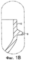
На фиг.1В показана деталь верхнего участка заготовки фиг.1А.On figv shows a detail of the upper portion of the workpiece figa.
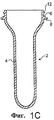
На фиг.1С показано поперечное сечение второй PET заготовки, подходящей для использования в соответствии с настоящим изобретением.1C shows a cross section of a second PET preform suitable for use in accordance with the present invention.
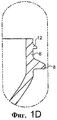
На фиг.1D показана деталь верхнего участка заготовки фиг.1С.FIG. 1D shows a detail of the upper portion of the blank of FIG. 1C.
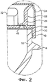
На фиг.2 показана деталь поперечного сечения горлышка и узла крышки, закрепленного на горлышке бутылки, изготовленной из заготовки фиг.1А и 1В.Figure 2 shows a detail of the cross section of the neck and cap assembly mounted on the neck of a bottle made from the blank of Figs. 1A and 1B.
На фиг.3 показана деталь, аналогичная показанной на фиг.2, со снятой крышкой, где можно видеть альтернативную конфигурацию для положения сварного шва на внутренней стороне боковой стенки горлышка бутылки.Figure 3 shows a detail similar to that shown in figure 2, with the cap removed, where you can see an alternative configuration for the position of the weld on the inner side of the side wall of the neck of the bottle.
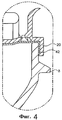
На фиг.4 показана деталь поперечного сечения горлышка и узла крышки, иллюстрирующая использование фольги завышенного размера в процессе горячей заливки с использованием технологии укупорки в соответствии с настоящим изобретением.Figure 4 shows a detail of the cross section of the neck and lid assembly, illustrating the use of oversized foil in the hot pouring process using the capping technology in accordance with the present invention.
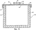
На фиг.5 показано сечение через горловину, установленную на композитном контейнере.Figure 5 shows a cross-section through a neck mounted on a composite container.
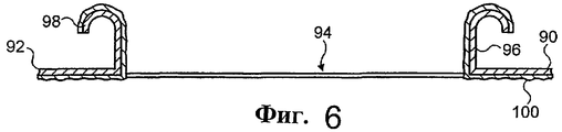
На фиг.6 показано сечение через торцевую крышку для консервной банки.Figure 6 shows a cross section through the end cover for a can.
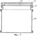
На фиг.7 показано сечение через торцевую крышку фиг.6 после сборки с горловиной и консервной банкой.Figure 7 shows a section through the end cap of figure 6 after assembly with the neck and a can.
Подробное описание предпочтительного варианта изобретенияDetailed Description of a Preferred Embodiment
Далее описаны варианты PET бутылки, показанной на фиг.1-4. Однако следует иметь в виду, что настоящее изобретение не ограничено случаем бутылок из такого материала, но обеспечивает особые дополнительные преимущества при его использовании для изготовления PET и PVC (поливинилхлоридных) бутылок, когда трудно образовать прочные сварные соединения. Показанный на фиг.5 вариант иллюстрирует использование технологии герметизации (укупоривания) в соответствии с настоящим изобретением для альтернативного контейнера. Показанный на фиг.6 и 7 вариант иллюстрирует применение предложенного способа для консервной банки.The following describes the options for the PET bottle shown in figures 1-4. However, it should be borne in mind that the present invention is not limited to the case of bottles of such material, but provides particular additional advantages when used for the manufacture of PET and PVC (polyvinyl chloride) bottles, when it is difficult to form strong welded joints. The embodiment shown in FIG. 5 illustrates the use of the sealing technology in accordance with the present invention for an alternative container. Shown in Fig.6 and 7 option illustrates the application of the proposed method for cans.
Заготовку 2 для PET бутылки получают известным путем литьевого формования из PET. Заготовка может быть изготовлена из модифицированного или смешанного PET материала, что обеспечивает улучшенную изоляцию (барьерные свойства) от проникновения газа. Например, PET может быть смешан с PEN. Заготовка 2 может быть изготовлена из PET гранул, с которыми смешивают маточную смесь ранее операции плавления гранул таким образом, что обычный PET перемешан с барьерной маточной смесью. Заготовка 2 также может быть получена за счет совместного литьевого формования таким образом, что она имеет несколько слоев.
Заготовка 2 имеет участок корпуса 4, содержащий материал, который может быть растянут при помощи формования раздувом, чтобы получить корпус бутылки и горлышко (шейку) 6. Участок горлышка 6 и участок корпуса 4 разделены при помощи кольца для транспортировки 8. Это кольцо 8 создано на стыке двух частей пресс-формы, которую используют для формовки заготовки. Участок горлышка 6 имеет пониженную высоту по сравнению с обычной заготовкой с резьбой, так как участок горлышка должен иметь только высоту, достаточную для поддержки юбки 20 горловины 22.The blank 2 has a body portion 4 containing material that can be stretched by blow molding to obtain a bottle body and a neck (neck) 6. The neck portion 6 and the body portion 4 are separated by a
Участок горлышка 6 преимущественно представляет собой простую цилиндрическую боковую стенку 10, не имеющую литых деталей (элементов), для обеспечения максимальной экономии и минимального веса, как это показано на фиг.1А и В. Однако ребро 12 может быть отформовано у открытого выходного отверстия 14 горлышка 6 или в непосредственной близости от него, как это показано на фиг.1D, для содействия установке в заданное положение горловины 22 или для облегчения выемки выдутой PET бутылки из пресс-формы для формования раздувом.The portion of the neck 6 is advantageously a simple
Горловина 22 имеет конструкцию в соответствии с описанной в публикации WO 99/61337, которая включена в данное описание в качестве ссылки. В этой публикации сборку горловины 22 и крышки 24 называют "горлышко и узел крышки". Горловина 22 имеет юбку 20 и заливочную воронку 26, на которые с защелкиванием надевают крышку 24. Крышкой 24 также может быть винтовая крышка. Юбка 20 соединяется с заливочной воронкой 26 у горизонтального фланца 30. Фольга 40 приварена вокруг отверстия (при этом она закрывает отверстие) в горловине и прикреплена к обратной стороне фланца 30. Кольцевая вытяжная конструкция 32 предусмотрена внутри заливочной воронки 26 для того, чтобы можно было удалять фольгу 40.The
В известной ранее сборке, применяемой при формовании при помощи экструзии с раздувом, фольга 40 является совершенно плоской, однако в соответствии с первым вариантом осуществления настоящего изобретения фольга 40 имеет участок 42, который спускается в направлении вниз вокруг внутренней стороны юбки 20 таким образом, что он может быть приварен к внешней поверхности боковой стенки 10. Вместо того чтобы полагаться на сварное соединение в плоскости отверстия и горизонтального фланца 30, теперь рассчитывают на сварное соединение между боковой стенкой 10 участка горлышка 6 и нисходящим участком 42 фольги 40, когда прикладывают срезающее усилие к сварному соединению при помощи кольцевой вытяжной конструкции 32, чтобы открыть бутылку, или когда сделана несанкционированная попытка отделить узел укупорки от бутылки.In the previously known assembly used in blow molding, the
В альтернативном варианте, показанном на фиг.3, плоская фольга 40 предусмотрена вокруг всей внутренней стороны горловины таким образом, что, когда горловину 22 надевают на корпус бутылки, фольга вдавливается вниз и прижимается к внутренней части боковой стенки 10. Это может быть осуществлено в ходе цикла индукционного нагревания, когда прикладывают направленное вниз усилие подгонки к заливочной воронке 26, которую принудительно вводят в горлышко 6 бутылки, когда материал фланца 30 деформируется. Обращенный внутрь выступ 46 образован вокруг внутренней стороны боковой стенки 10 для того, чтобы создать опору для покрытого фольгой фланца 30 в его полностью введенном положении, показанном на фиг.3. Нижняя поверхность фольги 40, 44 также будет уплотнять верхнюю горизонтальную поверхность 48 этого выступа 46. В этом случае кольцевой участок 44 фольги 40, который раньше, до деформирования, лежал под самой внешней частью фланца 30, теперь идет вверх от центрального участка фольги и приварен к внутренней стороне боковой стенки 10. Таким образом, в своем окончательном положении плоская фольга 40 получает форму чашки, которая заканчивается на горизонтальной верхней поверхности участка горлышка 6 или в непосредственной близости от него. Как и в описанном здесь выше варианте, сварное соединение с боковой стенкой 10 также создает скорее срезающее усилие, чем растягивающее усилие, когда фольгу 40 открывают при помощи кольцевой вытяжной конструкции или когда сделана попытка отделения узла укупорки за счет введения рычага под юбку 20.In the alternative embodiment shown in FIG. 3, a
Вместо использования технологии деформирования с получением показанной на фиг.3 конструкции горловина может быть отлита по этой форме и предназначена для введения в виде пробки в горлышко. В соответствии с этим вариантом участок фольги 44 идет вверх вокруг внешней стороны горловины. Сварное соединение с боковой стенкой 10 является менее чувствительным к короблению (деформации) горлышка 6, которое может случиться в ходе процесса горячей заливки или приложения теплоты для сварки. Это может создавать существенные деформации верхней поверхности заготовки, что не позволяет создать сварное соединение с этой поверхностью, в то время как сварное соединение с боковой стенкой заготовки может быть осуществлено.Instead of using deformation technology to obtain the design shown in FIG. 3, the neck can be molded in this form and is intended to be inserted as a stopper into the neck. According to this embodiment, the portion of the
На фиг.4 показана фольга 40 с завышенными размерами, но со сварным соединением к горлышку 6 в непосредственной близости от внешней стороны боковой стенки 10. Этот вариант особенно хорошо подходит для горячей заливки. В этом случае фольгу 40 вводят во внутреннюю часть горловины в ходе монтажа и позволяют ей прогибаться внутрь (как это показано на фиг.4) во время охлаждения после образования сварного соединения, чтобы частично снять (компенсировать) вакуум, созданный внутри корпуса бутылки. Это позволяет использовать эту технологию укупорки для корпусов бутылок, которые нуждаются в меньшем числе упрочняющих прижимных панелей, чтобы выдерживать вакуум, созданный после заливки.Figure 4 shows an
Этот тип технологии герметизации позволяет производить горячую заливку при температурах свыше 75°С без использования кристаллизации горлышка заготовки, так как некоторая деформация горлышка может быть скомпенсирована сварным соединением с боковой стенкой.This type of sealing technology allows hot pouring at temperatures above 75 ° C without using crystallization of the neck of the workpiece, since some deformation of the neck can be compensated by a welded joint to the side wall.
В описанных вариантах на чертежах показана горловина 22 с защелкиваемой крышкой 24. Однако, если бутылку используют для газированного продукта, то может быть предусмотрена заливочная воронка 26 с резьбой, которая соединяется с резьбовой крышкой и позволяет производить повторную укупорку.In the described embodiments, the
В том случае, когда корпус бутылки имеет внутреннее или внешнее барьерное покрытие на внутренней или на внешней стороне корпуса бутылки, то сварное соединение с боковой стенкой 10 может быть произведено там, где пластмассовый материал не имеет покрытия, или, если материал покрытия является свариваемым, там, где имеется покрытие. Альтернативно, покрытие может заканчиваться, не доходя до верхней части боковой стенки 10.In the case where the bottle body has an internal or external barrier coating on the inside or on the outside of the bottle body, then a welded connection to the
В контейнере, показанном на фиг.5, эквивалентные детали имеют одинаковые позиционные обозначения с дополнительным штрихом. В этом контейнере используют горловину 22, причем композитный контейнер 80 представляет собой цилиндр из многослойного картона с основанием. В этой конструкции боковые стенки 82 контейнера являются в действительности боковыми стенками горлышка 6, если использовать терминологию, которую применяют в данном описании и в формуле изобретения. Многослойный картон (который может иметь и другие слои, такие как алюминиевая фольга или EVOH) имеет внешнее и/или внутреннее покрытие 84 в виде пластмассового покрытия, например, из полипропилена, полиэтилена или PET, которое приваривают за счет аналогичного покрытия на участке фольги 42 к боковой стенке 6, а также к горизонтальной верхней поверхности 86 боковой стенки 82.In the container shown in FIG. 5, equivalent parts have the same reference numerals with an additional stroke. The
Следует иметь в виду, что конструкции, аналогичные показанной на фиг.5, могут быть использованы для стальных консервных банок с пластмассовым покрытием.It should be borne in mind that structures similar to those shown in FIG. 5 can be used for plastic coated steel cans.
Как композитный, так и металлический контейнеры также могут иметь пластмассовую или покрытую пластмассой верхнюю или торцевую крышку, которая ограничивает отдельный участок горлышка, с которым может быть соединена горловина 22 при помощи любого из ранее описанных путей. В этом варианте торцевая крышка может быть соединена с ее горловиной независимо от операции заливки и приварена к корпусу консервной банки как готовый блок.Both composite and metal containers can also have a plastic or plastic coated top or end cap that defines a separate portion of the neck to which
На фиг.6 показана торцевая крышка, подходящая для такого применения. Покрытая пластмассой торцевая крышка 90 имеет внешнюю кромку 92, предназначенную для припаивания к консервной банке или закатывания консервной банки, и центральное отверстие 94, которое ограничено боковой стенкой 96. Кромки 98 боковой стенки 96 имеют поворот наружу и вниз вокруг отверстия, для того чтобы входить в зацепление с юбкой 20 горловины 22. Когда только нижняя поверхность торцевой крышки 90 покрыта пластмассой, тогда это пластмассовое покрытие 100 обращено к фольге 40. Затем проводят подгонку горловины к торцевой крышке 90 в соответствии с ранее описанным. Так как закатывание консервной банки с использованием торцевой крышки обычно проводят очень быстро, преимущественно следует произвести предварительную сборку горловин с торцевыми крышками, а затем произвести закатывание готового блока по его кромке 92 к боковым стенкам 102 консервной банки.6 shows an end cap suitable for such an application. The plastic-coated
Claims (15)
Applications Claiming Priority (4)
| Application Number | Priority Date | Filing Date | Title |
|---|---|---|---|
| GB0201718.4 | 2002-01-25 | ||
| GBGB0201718.4A GB0201718D0 (en) | 2002-01-25 | 2002-01-25 | Bottle closures |
| GB0228182.2 | 2002-12-03 | ||
| GB0228182A GB2384478B (en) | 2002-01-25 | 2002-12-03 | Container closures |
Publications (2)
| Publication Number | Publication Date |
|---|---|
| RU2004123255A RU2004123255A (en) | 2005-03-27 |
| RU2295477C2 true RU2295477C2 (en) | 2007-03-20 |
Family
ID=27614802
Family Applications (1)
| Application Number | Title | Priority Date | Filing Date |
|---|---|---|---|
| RU2004123255/12A RU2295477C2 (en) | 2002-01-25 | 2003-01-16 | Container sealing devices |
Country Status (16)
| Country | Link |
|---|---|
| US (1) | US7578040B2 (en) |
| EP (1) | EP1470047B1 (en) |
| JP (1) | JP2005515125A (en) |
| CN (1) | CN1330531C (en) |
| AT (1) | ATE306419T1 (en) |
| BR (1) | BR0302852B1 (en) |
| CA (1) | CA2473895C (en) |
| DE (1) | DE60301858T2 (en) |
| DK (1) | DK1470047T3 (en) |
| ES (1) | ES2250869T3 (en) |
| HK (1) | HK1074192A1 (en) |
| MX (1) | MXPA04007132A (en) |
| NZ (1) | NZ534253A (en) |
| PL (1) | PL210146B1 (en) |
| RU (1) | RU2295477C2 (en) |
| WO (1) | WO2003062061A1 (en) |
Families Citing this family (9)
| Publication number | Priority date | Publication date | Assignee | Title |
|---|---|---|---|---|
| GB0415204D0 (en) * | 2004-07-07 | 2004-08-11 | Dubois Ltd | Packaging article |
| GB2433496B (en) * | 2005-12-22 | 2007-11-21 | Bapco Closures Res Ltd | Tamper evident drinking fitment |
| US8678215B2 (en) | 2006-08-21 | 2014-03-25 | Tropicana Products, Inc. | Container having improved pouring characteristics |
| WO2008024775A1 (en) * | 2006-08-21 | 2008-02-28 | Tropicana Products, Inc. | Closure for container |
| DE102009009415A1 (en) * | 2009-02-18 | 2010-08-26 | Heipha Gmbh | Container with a septum closure and cap with septum closure |
| JP5486753B2 (en) * | 2009-11-30 | 2014-05-07 | 日本テトラパック株式会社 | Packaging container manufacturing method, spout stopper and packaging container |
| US9963274B2 (en) * | 2012-11-20 | 2018-05-08 | Aptargroup, Inc. | Closure having a liner and pull ring |
| CN110403428A (en) * | 2019-08-22 | 2019-11-05 | 深圳市中旻科技有限公司 | A kind of cup lid vacuum spacer structure and preparation method thereof |
| CN115106735B (en) * | 2021-06-01 | 2023-12-29 | 青岛航天半导体研究所有限公司 | Buckle cover feeding device of electric component bearing box |
Family Cites Families (14)
| Publication number | Priority date | Publication date | Assignee | Title |
|---|---|---|---|---|
| US3504817A (en) * | 1968-05-14 | 1970-04-07 | Owens Illinois Inc | Closure and method of applying same |
| US4059201A (en) * | 1977-03-14 | 1977-11-22 | J. L. Clark Manufacturing Co. | Container closure with foil seal |
| US4359169A (en) * | 1981-08-28 | 1982-11-16 | Container Corporation Of America | Container end closure arrangement |
| US4457455A (en) * | 1981-10-13 | 1984-07-03 | Philip Meshberg | Collapsible container |
| JPS6415087A (en) | 1987-07-08 | 1989-01-19 | Nippi Kikai Kk | Taking-in apparatus for leather and the like |
| US4815618A (en) * | 1988-04-25 | 1989-03-28 | Sunbeam Plastics Corporation | Tamper indicating dispenser closure |
| CN1035086A (en) * | 1988-11-10 | 1989-08-30 | 熊绍裕 | The design arrangement method of passenger train deck chair carriage guest room |
| FR2747371B1 (en) * | 1996-04-10 | 1998-05-22 | Nord Est Dev | CONTAINER WITH SEALED CLOSURE BEFORE OPENING, SUCH A CONTAINER CONTAINING CONTENT AND METHOD FOR PACKAGING SUCH CONTENT |
| GB2337740B (en) | 1998-05-26 | 2000-11-15 | Spreckelsen Mcgeough Ltd | Fluid packaging |
| GB2350105B (en) * | 1999-05-20 | 2001-04-11 | Spreckelsen Mcgeough Ltd | Resealable gas impermeable sealing assembly |
| US6375025B1 (en) | 1999-08-13 | 2002-04-23 | Graham Packaging Company, L.P. | Hot-fillable grip container |
| US6349839B1 (en) | 1999-08-13 | 2002-02-26 | Graham Packaging Company, L.P. | Hot-fillable wide-mouth grip jar |
| DE60022794T2 (en) * | 2000-11-02 | 2006-07-20 | Bapco Closures Research Ltd., Woking | RE-SEALABLE BREAKTHROUGH SEAL |
| US6364180B1 (en) * | 2000-11-29 | 2002-04-02 | Alberto C. Cardenas | Container for dispensing oil into an engine |
-
2003
- 2003-01-16 CN CNB038026376A patent/CN1330531C/en not_active Expired - Lifetime
- 2003-01-16 AT AT03700904T patent/ATE306419T1/en active
- 2003-01-16 CA CA2473895A patent/CA2473895C/en not_active Expired - Lifetime
- 2003-01-16 PL PL369658A patent/PL210146B1/en unknown
- 2003-01-16 DK DK03700904T patent/DK1470047T3/en active
- 2003-01-16 NZ NZ534253A patent/NZ534253A/en not_active IP Right Cessation
- 2003-01-16 MX MXPA04007132A patent/MXPA04007132A/en active IP Right Grant
- 2003-01-16 EP EP03700904A patent/EP1470047B1/en not_active Expired - Lifetime
- 2003-01-16 JP JP2003561963A patent/JP2005515125A/en active Pending
- 2003-01-16 WO PCT/GB2003/000190 patent/WO2003062061A1/en active IP Right Grant
- 2003-01-16 BR BRPI0302852-6B1A patent/BR0302852B1/en active IP Right Grant
- 2003-01-16 DE DE60301858T patent/DE60301858T2/en not_active Expired - Lifetime
- 2003-01-16 ES ES03700904T patent/ES2250869T3/en not_active Expired - Lifetime
- 2003-01-16 RU RU2004123255/12A patent/RU2295477C2/en active
-
2004
- 2004-07-23 US US10/898,459 patent/US7578040B2/en not_active Expired - Lifetime
-
2005
- 2005-08-02 HK HK05106612A patent/HK1074192A1/en not_active IP Right Cessation
Also Published As
| Publication number | Publication date |
|---|---|
| RU2004123255A (en) | 2005-03-27 |
| PL210146B1 (en) | 2011-12-30 |
| DE60301858D1 (en) | 2006-02-23 |
| CN1622896A (en) | 2005-06-01 |
| BR0302852B1 (en) | 2013-12-24 |
| CA2473895A1 (en) | 2003-07-31 |
| CA2473895C (en) | 2010-03-16 |
| CN1330531C (en) | 2007-08-08 |
| ATE306419T1 (en) | 2005-10-15 |
| HK1074192A1 (en) | 2005-11-04 |
| PL369658A1 (en) | 2005-05-02 |
| BR0302852A (en) | 2004-04-27 |
| US20050072816A1 (en) | 2005-04-07 |
| DE60301858T2 (en) | 2006-06-22 |
| JP2005515125A (en) | 2005-05-26 |
| DK1470047T3 (en) | 2006-03-06 |
| ES2250869T3 (en) | 2006-04-16 |
| EP1470047B1 (en) | 2005-10-12 |
| NZ534253A (en) | 2007-11-30 |
| MXPA04007132A (en) | 2005-05-16 |
| US7578040B2 (en) | 2009-08-25 |
| WO2003062061A1 (en) | 2003-07-31 |
| EP1470047A1 (en) | 2004-10-27 |
Similar Documents
| Publication | Publication Date | Title |
|---|---|---|
| US7963409B2 (en) | Resealable closures | |
| AU2005225604B2 (en) | Closure with integral gas barrier | |
| JP2009113867A (en) | Container closures | |
| RU2295477C2 (en) | Container sealing devices | |
| KR20100017663A (en) | Closure for a sealed container of a pourable food product, and method of producing thereof | |
| AU2003202049A1 (en) | Container closures | |
| AU2007298741A1 (en) | Carton fitments | |
| CA2629094C (en) | Method of producing plastic tops for sealed containers of pourable food products, and container plastic tops so produced | |
| US20050121452A1 (en) | Containers and methods of production thereof | |
| US20070157561A1 (en) | Induction sealing heat profile improvement |
Legal Events
| Date | Code | Title | Description |
|---|---|---|---|
| PC41 | Official registration of the transfer of exclusive right |
Effective date: 20211027 |