RU2294541C1 - Method for determining speed of thermo-capillary flow near side surface of washer-shaped vial - Google Patents
Method for determining speed of thermo-capillary flow near side surface of washer-shaped vial Download PDFInfo
- Publication number
- RU2294541C1 RU2294541C1 RU2005115612/28A RU2005115612A RU2294541C1 RU 2294541 C1 RU2294541 C1 RU 2294541C1 RU 2005115612/28 A RU2005115612/28 A RU 2005115612/28A RU 2005115612 A RU2005115612 A RU 2005115612A RU 2294541 C1 RU2294541 C1 RU 2294541C1
- Authority
- RU
- Russia
- Prior art keywords
- flow
- bubble
- curvature
- thermo
- washer
- Prior art date
Links
Images
Landscapes
- Indicating Or Recording The Presence, Absence, Or Direction Of Movement (AREA)
- Investigating Or Analyzing Materials Using Thermal Means (AREA)
Abstract
Description
Изобретение относится к области бесконтактных методов диагностики течения жидкостей в микромасштабе и может быть использовано для определения скорости течения у поверхности пузырька, движущегося в канале микрофлуидного насоса или оптического переключателя [1-2].The invention relates to the field of non-contact methods for diagnosing the flow of liquids at the microscale and can be used to determine the flow velocity at the surface of a bubble moving in the channel of a microfluidic pump or optical switch [1-2].
Известен способ [3] измерения скорости течения жидкости, состоящий в следующем: жидкий поток засевают трассерными частицами меченными флюоресцирующим красителем, затем поперечное сечение потока облучают последовательными импульсами лазерного света сфокусированного цилиндрической линзой в лист и, одновременно с подачей импульсов, выполняют видеозахват изображений. Далее, на основе этих изображений, с помощью компьютерной программы фиксируют положение выбранной частицы на последовательности кадров и измеряют ее смещение за период между двумя импульсами, затем вычисляют скорость.There is a method [3] for measuring the flow rate of a liquid, which consists in the following: a liquid stream is seeded with tracer particles labeled with a fluorescent dye, then the cross section of the stream is irradiated with successive pulses of laser light focused by a cylindrical lens into the sheet and, simultaneously with the supply of pulses, perform image capture. Further, on the basis of these images, using a computer program, the position of the selected particle is recorded on a sequence of frames and its displacement is measured for the period between two pulses, then the speed is calculated.
Однако в микрофлуидике этот метод имеет ряд недостатков. Выбор трассерных частиц критичен для каждого изучаемого случая. С одной стороны, частицы должны быть достаточно малыми, чтобы отслеживать линии тока и не блокировать течение, а с другой стороны - достаточно большими, чтобы демпфировать броуновское движение, которое вносит погрешность в измерения скорости. Кроме того, сложный алгоритм обработки данных требует специализированной компьютерной программы.However, in microfluidics this method has several disadvantages. The choice of tracer particles is critical for each case studied. On the one hand, the particles must be small enough to track the streamlines and not block the flow, and on the other hand, large enough to damp the Brownian motion, which introduces an error in the velocity measurements. In addition, a complex data processing algorithm requires a specialized computer program.
При диагностике течения индуцируемого малыми (до 10°С) локальными тепловыми возмущениями (например, конвекция в микромасштабе вызванная тепловым действием пучка света [1, 4]), применение этого способа налагает ограничения на выбор длины волны индуцирующего излучения, которое не должно нагревать трассерные частицы и интерферировать на них.When diagnosing the flow induced by small (up to 10 ° C) local thermal disturbances (for example, convection at the microscale caused by the thermal action of the light beam [1, 4]), the application of this method imposes restrictions on the choice of the wavelength of the inducing radiation, which should not heat the tracer particles and interfere with them.
Целью данного изобретения является упрощение способа определения скорости термокапиллярного течения у поверхности шайбовидного пузырька.The aim of the present invention is to simplify the method for determining the velocity of thermocapillary flow at the surface of the washer-like bubble.
Цель достигается путем измерения статической кривизны и суммарной кривизны наблюдаемой визуально боковой поверхности пузырька, деформация которой вызвана термокапиллярным течением индуцированным пучком света. При этом суммарная кривизна наблюдаемой визуально деформированной поверхности пузырька находится согласно принципу суперпозиции кривизн [5, 6].The goal is achieved by measuring the static curvature and the total curvature of the visually observed lateral surface of the bubble, the deformation of which is caused by the thermocapillary flow of the induced light beam. In this case, the total curvature of the observed visually deformed surface of the bubble is found according to the principle of superposition of curvatures [5, 6].
Детальный механизм формирования суммарной кривизны (Фиг.1) и вывод выражения для скорости следующие. Боковая поверхность шайбовидного пузырька 1, зажатого между двумя прозрачными для излучения пластинами 2 имеет постоянную статическую кривизну χS, Фиг.1(а). В момент, когда прилегающая к боковой поверхности пузырька 1, поглощающая жидкость 3 нагревается пучком света 4, Фиг.1(б), поверхностное натяжение на поверхности пузырька уменьшается, и возникает поле термокапиллярных сил 5, вызывающих унос жидкости из зоны облучения. Вследствие этого боковая поверхность пузырька приобретает динамическую кривизну χd, которая складывается по принципу суперпозиции [5, 6] с кривизной χS до облучения. В итоге, визуально наблюдаемая деформация 6 боковой поверхности пузырька 1 имеет суммарную кривизну [6]A detailed mechanism for the formation of total curvature (Figure 1) and the derivation of the expression for the speed are as follows. The lateral surface of the
![]()
![]()
Динамическая кривизна χd создает избыточное капиллярное давление в пузырьке pσ=σ·χd и возвратные потоки жидкости с динамическим напором pi=ρu2/2, генерирующие два согласованных вихря 7 в жидкости [4]. Здесь u - искомая скорость термокапиллярного течения у поверхности шайбовидного пузырька, которая из условия баланса этих давлений и принципа суперпозиции (1) имеет видDynamic curvature χ d creates excessive capillary pressure in the bubble p σ = σ · χ d and return fluid flows to the dynamic pressure p i = ρu 2/2, generating two coherent vortex 7 in a liquid [4]. Here u is the desired velocity of the thermocapillary flow near the surface of the washer bubble, which, from the condition of the balance of these pressures and the superposition principle (1), has the form
![]()
![]()
плотность ρ жидкости и ее коэффициент поверхностного натяжения σ являются табличными величинами.fluid density ρ and its surface tension coefficient σ are tabulated values.
Далее, скорость u термокапиллярного течения находят по результату измерения суммарной кривизны χ боковой поверхности пузырька и ее статической кривизны χS Фиг.1(а).Further, the velocity u of the thermocapillary flow is found by measuring the total curvature χ of the side surface of the bubble and its static curvature χ S of Fig. 1 (a).
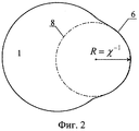
На Фиг.2 показана схема измерения кривизны χ. Используя снимок деформированного пузырька, полученный фотографированием или видеосъемкой, и считая, что деформированная поверхность 6 представляет собой участок некой окружности 8, в любом графическом редакторе достраивают эту окружность и измеряют радиус ее кривизны R=χ-1. Зная статическую кривизну пузырька χS=RS -1, по формуле (2) вычисляют скорость термокапиллярного течения u.Figure 2 shows a diagram for measuring the curvature χ. Using a photograph of a deformed bubble obtained by photographing or filming, and assuming that the
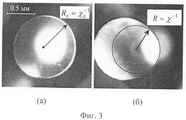
На Фиг.3 приведены кадры пузырьков: (а) - пучок света спроецирован в смачивающую пленку под пузырьком и не оказывает теплового действия на боковую поверхность; (б) - пучок света нагревает приповерхностную область пузырька, что вызывает термокапиллярное течение, которое деформирует боковую поверхность пузырька. Здесь измерение кривизн проводили в редакторе MSWord, куда вставляли эти кадры и с помощью инструмента WordArt достраивали окружность и измеряли ее кривизну.Figure 3 shows the frames of the bubbles: (a) - the light beam is projected into the wetting film under the bubble and does not have a thermal effect on the side surface; (b) - a light beam heats the near-surface region of the bubble, which causes a thermocapillary flow that deforms the lateral surface of the bubble. Here, the curvature measurement was carried out in the MSWord editor, where these frames were inserted and the circle was completed using the WordArt tool and its curvature was measured.
Пример. В таблице даны средние значения скорости термокапиллярного течения в разных жидкостях, возбуждаемого пучком света у поверхности пузырьков, полученные предлагаемым способом.Example. The table shows the average values of the velocity of thermocapillary flow in different liquids, excited by a light beam at the surface of the bubbles, obtained by the proposed method.
В опытах использовали пузырьки с RS от 0.4 до 0.6 мм, зажатые в ячейке с зазором 50 мкм, заполняемой окрашенными жидкостями, которые облучали сфокусированным излучением ртутной лампы. Поглощаемая мощность жидкостей была одинаковой и равной 30 мВт.In the experiments, we used bubbles with R S from 0.4 to 0.6 mm, clamped in a cell with a gap of 50 μm, filled with colored liquids, which were irradiated with focused radiation of a mercury lamp. The absorbed power of the liquids was the same and equal to 30 mW.
Разница между значениями, полученными по предлагаемому способу и оцененными с помощью трассерных частиц, составляет менее 15%.The difference between the values obtained by the proposed method and estimated using tracer particles is less than 15%.
Таким образом, предлагаемый способ, отличаясь простотой, имеет ряд преимуществ: не требует засева трассерных частиц, дополнительных зондирующих пучков и оптики для них, а также не требует программного обеспечения для расчета скорости.Thus, the proposed method, characterized by simplicity, has several advantages: it does not require tracer particles, additional probing beams and optics for them, and also does not require software for calculating the speed.
Способ можно использовать для определения скорости термокапиллярных течений, вызванных не только локальным действием пучка света на поверхность пузырька, но и за счет локального нагрева этой поверхности резистивными нагревателями. В этом случае необходимо лишь подсвечивать пузырек рассеянным светом.The method can be used to determine the velocity of thermocapillary flows caused not only by the local action of a light beam on the surface of the bubble, but also due to local heating of this surface by resistive heaters. In this case, it is only necessary to illuminate the bubble with diffused light.
ЛИТЕРАТУРАLITERATURE
1. Sato M., Horie M., Kitano N. et. al. Thermocapillary optical switch. // Hitachi Cable Review. 2001. №.20. P.19-24.1. Sato M., Horie M., Kitano N. et. al. Thermocapillary optical switch. // Hitachi Cable Review. 2001. No.20. P.19-24.
2. Jun Т.К., Kim C.-J. Valveless pumping using traversing vapor bubbles in microchannels. // J. Applied Physics. 1998. Vol.83. №.11. P.5658-5664.2. Jun T.K., Kim C.-J. Valveless pumping using traversing vapor bubbles in microchannels. // J. Applied Physics. 1998. Vol. 83. No. 11. P.5658-5664.
3. URL: http://www.lavison.de/download/educational/pivintroduction.pdf3. URL: http://www.lavison.de/download/educational/pivintroduction.pdf
4. Безуглый Б.А., Иванова Н.А. Манипуляция газовым пузырьком в ячейке Хеле-Шоу с помощью пучка света. // Письма в ЖТФ. 2002. Том. 28. Вып.19. С.71-75.4. Bezugly B.A., Ivanova N.A. Manipulating a gas bubble in a Hele-Shaw cell using a beam of light. // Letters to the ZhTF. 2002. Vol. 28. Issue 19. S.71-75.
5. Безуглый Б.А., Тарасов О.А., Федорец А.А. Модифицированный метод наклонной пластинки измерения краевого угла смачивания. // Коллоидный журнал. 2001. №6. С.735-741.5. Bezugly B.A., Tarasov O.A., Fedorets A.A. A modified method of an inclined plate for measuring the wetting angle. // Colloidal journal. 2001. No.6. S.735-741.
6. Тарасов О.А. Аддитивность динамической кривизны термокапиллярного углубления и статической кривизны мениска смачивания. // Коллоидный журнал. 2005. Т.67. №2. С.1-9.6. Tarasov O.A. Additivity of the dynamic curvature of the thermocapillary recess and the static curvature of the wetting meniscus. // Colloidal journal. 2005.V. 67. No. 2. S.1-9.
Claims (1)
Priority Applications (1)
| Application Number | Priority Date | Filing Date | Title |
|---|---|---|---|
| RU2005115612/28A RU2294541C1 (en) | 2005-05-23 | 2005-05-23 | Method for determining speed of thermo-capillary flow near side surface of washer-shaped vial |
Applications Claiming Priority (1)
| Application Number | Priority Date | Filing Date | Title |
|---|---|---|---|
| RU2005115612/28A RU2294541C1 (en) | 2005-05-23 | 2005-05-23 | Method for determining speed of thermo-capillary flow near side surface of washer-shaped vial |
Publications (2)
| Publication Number | Publication Date |
|---|---|
| RU2005115612A RU2005115612A (en) | 2006-11-27 |
| RU2294541C1 true RU2294541C1 (en) | 2007-02-27 |
Family
ID=37664243
Family Applications (1)
| Application Number | Title | Priority Date | Filing Date |
|---|---|---|---|
| RU2005115612/28A RU2294541C1 (en) | 2005-05-23 | 2005-05-23 | Method for determining speed of thermo-capillary flow near side surface of washer-shaped vial |
Country Status (1)
| Country | Link |
|---|---|
| RU (1) | RU2294541C1 (en) |
-
2005
- 2005-05-23 RU RU2005115612/28A patent/RU2294541C1/en not_active IP Right Cessation
Non-Patent Citations (1)
| Title |
|---|
| Письма в ЖТФ. 2002, том. 28, вып.19, сс.71-72. Коллоидный журнал, 2001, №6, сс.735-741. J. Applied Physics. 1998, vol.83, №.11, pp.5658-5664. Кремлевский П.П. Расходомеры и счетчики количества. Справочник. Изд.4. - Л.: Машиностроение, 1989, сс.617-621. * |
Also Published As
| Publication number | Publication date |
|---|---|
| RU2005115612A (en) | 2006-11-27 |
Similar Documents
| Publication | Publication Date | Title |
|---|---|---|
| Lindken et al. | Micro-particle image velocimetry (µPIV): recent developments, applications, and guidelines | |
| LeClair et al. | A theoretical and experimental study of the internal circulation in water drops falling at terminal velocity in air | |
| Kumar et al. | 3D3C velocimetry measurements of an electrothermal microvortex using wavefront deformation PTV and a single camera | |
| Bouche et al. | Mixing in a swarm of bubbles rising in a confined cell measured by mean of PLIF with two different dyes | |
| Weinert et al. | Optically driven fluid flow along arbitrary microscale patterns using thermoviscous expansion | |
| Mohammadi et al. | Experimental techniques for bubble dynamics analysis in microchannels: a review | |
| Khodaparast et al. | A micro particle shadow velocimetry (μPSV) technique to measure flows in microchannels | |
| Gulati et al. | Direct measurements of viscoelastic flows of DNA in a 2: 1 abrupt planar micro-contraction | |
| Kazoe et al. | Evanescent wave-based particle tracking velocimetry for nanochannel flows | |
| Rivière et al. | Convection flows driven by laser heating of a liquid layer | |
| Meinhart et al. | Micron-resolution velocimetry techniques | |
| Keißner et al. | Directional fluid transport along artificial ciliary surfaces with base-layer actuation of counter-rotating orbital beating patterns | |
| Kuang et al. | Study on factors enhancing photobleaching effect of fluorescent dye | |
| de Blois et al. | Swimming droplets in 1D geometries: an active Bretherton problem | |
| Bouzigues et al. | Using surface force apparatus, diffusion and velocimetry to measure slip lengths | |
| RU2294541C1 (en) | Method for determining speed of thermo-capillary flow near side surface of washer-shaped vial | |
| Vasudevan et al. | Laser induced fluorescence measurement of liquid film thickness and variation in Taylor flow | |
| Wynne et al. | Electrokinetic characterization of individual nanoparticles in nanofluidic channels | |
| Yamaguchi et al. | μ-PIV measurements of the ensemble flow fields surrounding a migrating semi-infinite bubble | |
| Sinton et al. | Microfluidic velocimetry with near-wall resolution | |
| Liu et al. | Mapping vortex-like hydrodynamic flow in microfluidic networks using fluorescence correlation spectroscopy | |
| Ansari et al. | Flow visualization of a bubble penetration through porous media in SAGD process using µSPIV | |
| Blonski et al. | Analysis of turbulence in a micro-channel emulsifier | |
| Chesneau et al. | Dynamics and flow characterization of liquid fountains produced by light scattering | |
| Schembri et al. | Velocimetry in microchannels using photobleached molecular tracers: a tool to discriminate solvent velocity in flows of suspensions |
Legal Events
| Date | Code | Title | Description |
|---|---|---|---|
| MM4A | The patent is invalid due to non-payment of fees |
Effective date: 20090524 |
|
| NF4A | Reinstatement of patent |
Effective date: 20110227 |
|
| MM4A | The patent is invalid due to non-payment of fees |
Effective date: 20150524 |