RU2293393C2 - Force switch - Google Patents
Force switch Download PDFInfo
- Publication number
- RU2293393C2 RU2293393C2 RU2004117866/09A RU2004117866A RU2293393C2 RU 2293393 C2 RU2293393 C2 RU 2293393C2 RU 2004117866/09 A RU2004117866/09 A RU 2004117866/09A RU 2004117866 A RU2004117866 A RU 2004117866A RU 2293393 C2 RU2293393 C2 RU 2293393C2
- Authority
- RU
- Russia
- Prior art keywords
- flow
- axial direction
- outflow
- elevations
- power switch
- Prior art date
Links
Images


Classifications
-
- H—ELECTRICITY
- H01—ELECTRIC ELEMENTS
- H01H—ELECTRIC SWITCHES; RELAYS; SELECTORS; EMERGENCY PROTECTIVE DEVICES
- H01H33/00—High-tension or heavy-current switches with arc-extinguishing or arc-preventing means
- H01H33/70—Switches with separate means for directing, obtaining, or increasing flow of arc-extinguishing fluid
- H01H33/88—Switches with separate means for directing, obtaining, or increasing flow of arc-extinguishing fluid the flow of arc-extinguishing fluid being produced or increased by movement of pistons or other pressure-producing parts
- H01H2033/888—Deflection of hot gasses and arcing products
Landscapes
- Circuit Breakers (AREA)
- Arc-Extinguishing Devices That Are Switches (AREA)
Abstract
Description
Изобретение относится к силовому выключателю с подвижной в аксиальном направлении контакт-деталью и с движущимся в случае коммутации в аксиальном направлении потоком дугогасящего газа, который коаксиально окружен устройством направления потока, которое имеет в боковой поверхности по крайней мере одно отверстие истечения для отклонения по крайней мере одной части потока дугогасящего газа в направление истечения.The invention relates to a circuit breaker with an axially movable contact part and moving in the case of axial commutation of an extinguishing gas stream that is coaxially surrounded by a flow direction device that has at least one outflow opening in the side surface to deflect at least one parts of the gas flow in the direction of flow.
Подобный силовой выключатель является известным, например, из патента DE 19953560 C1. Там описан силовой выключатель, размыкающий блок которого расположен внутри герметизирующего корпуса. Возможно возникающий в процессе выключения размыкающего блока силового выключателя дугогасящий газ там отводится от раствора контактов частично внутри полой контактной трубы. На конце полой контактной трубы, обращенном от раствора контактов, контактная труба имеет выходные отверстия, из которых выступает дугогасящий газ. Дугогасящий газ выходит в пространство, которое ограничено устройством направления потока. Это устройство направления потока является в основном цилиндрическим и содержит в своей боковой поверхности отверстия истечения. Через эти отверстия истечения дугогасящий газ может выступать из ограниченного устройством направления потока пространства и вытекать в окружающий размыкающий блок силового выключателя объем, заполненный изолирующим газом.A similar circuit breaker is known, for example, from DE 19953560 C1. A power switch is described there, the trip unit of which is located inside the sealing case. Probably arising during the shutdown of the disconnecting block of the power switch arcing gas there is removed from the contact solution partially inside the hollow contact tube. At the end of the hollow contact tube, facing away from the contact solution, the contact tube has outlet openings from which an extinguishing gas protrudes. An extinguishing gas escapes into a space that is limited by a flow direction device. This flow directing device is generally cylindrical and contains outflow openings in its side surface. Through these outflow openings, an extinguishing gas can protrude from the space flow direction limited by the device and flow into the surrounding disconnecting block of the power switch, the volume filled with insulating gas.
Для направления выступающего из отверстий истечения дугогасящего газа в определенное направление в соответствие отверстиям истечения приданы отклоняющие колпаки. Эти отклоняющие колпаки отклоняют выступающий дугогасящий газ в аксиальное направление размыкающего блока. Это отклонение является необходимым, чтобы предотвратить прямое обтекание герметизирующего корпуса дугогасящим газом. При подобном обтекании существовала бы возможность ослабления газовой изоляции.To direct the protruding gas from the outlet of the extinguishing gas in a certain direction, deflecting caps are given in accordance with the outlet openings. These deflecting caps deflect the protruding extinguishing gas in the axial direction of the trip unit. This deviation is necessary in order to prevent direct flow of the extinguishing gas around the sealing body. With such a flow there would be the possibility of weakening the gas insulation.
Придание в соответствие отверстиям истечения отклоняющих колпаков представляет собой сложную конструкцию, поскольку отклоняющие колпаки приданы в соответствие каждому отверстию истечения по отдельности и каждый отклоняющий колпак должен быть по отдельности закреплен на устройстве направления потока. Вследствие относительно сложного размещения отверстий истечения и отклоняющих колпаков относительно друг друга также простой способ изготовления, например способ литья, для подобного расположения не рекомендуется.Matching the outflow openings of the deflecting caps is a complex structure, since the deflecting caps are associated with each outflow opening individually and each deflecting cap must be individually mounted to the flow direction device. Owing to the relatively complicated arrangement of the outflow openings and the deflecting caps relative to each other, also a simple manufacturing method, for example a casting method, is not recommended for such an arrangement.
В основе настоящего изобретения лежит задача выполнения силового выключателя названного выше вида так, чтобы оптимизировать отклонение дугогасящего газа, выступающего из отверстия истечения.The basis of the present invention is the task of performing a circuit breaker of the above type so as to optimize the deflection of the extinguishing gas protruding from the outlet opening.
Эта задача в случае силового выключателя названного выше вида решается согласно изобретению за счет того, что направление истечения направлено тангенциально к боковой поверхности, в основном перпендикулярно, к аксиальному направлению.This problem in the case of a power switch of the type mentioned above is solved according to the invention due to the fact that the direction of flow is directed tangentially to the side surface, mainly perpendicular to the axial direction.
За счет тангенциального к боковой поверхности направления истечения участок пути, стоящий в распоряжении для оттока, удлиняется. В случае сложной, имеющей неровности и изрезанной боковой поверхности устройства направления потока для определения тангенциального направления должна определяться соответствующая оболочка, чтобы устанавливать соответственно выгодное тангенциальное направление. Под тангенциальным направлением следует понимать также направления, которые отклоняются от математически строгой касательной до 45° внутри азимутальной плоскости. При соответствующем выборе размеров использование отклоняющих колпаков, которые приданы в соответствие отверстиям истечения, не является необходимым. За счет этого происходит уменьшение числа необходимых деталей и наряду с упрощенным отклонением дугогасящего газа тем самым также уменьшение расходов на изготовление. Вследствие упрощенной конструкции для изготовления направляющего устройства потока могут использоваться также простые технологии литья. Путем фрезерования, сверления или другой подходящей технологии отверстия истечения могут быть введены в боковую поверхность. Наряду с упрощенным направлением дугогасящего газа может достигаться, кроме того, улучшенное завихрение дугогасящего газа.Due to the direction of flow tangential to the lateral surface, the stretch of the path available for outflow is lengthened. In the case of a complex, irregular, and rugged side surface of the flow direction device, the corresponding shell must be determined to determine the tangential direction in order to establish a correspondingly advantageous tangential direction. The tangential direction should also be understood as directions that deviate from a mathematically strict tangent to 45 ° inside the azimuthal plane. With the appropriate choice of sizes, the use of deflecting caps, which are adapted to the outflow openings, is not necessary. Due to this, there is a decrease in the number of necessary parts and, along with a simplified deviation of the extinguishing gas, thereby also reducing manufacturing costs. Due to the simplified design, simple casting techniques can also be used to manufacture the flow guide. By milling, drilling, or other suitable technology, outflow openings can be introduced into the side surface. Along with the simplified direction of the extinguishing gas, an improved turbulence of the extinguishing gas can also be achieved.
Далее может быть предусмотрено, что множество отверстий истечения сопоставлены друг с другом так, что их соответствующие направления истечения пересекаются.It may further be provided that the plurality of outflow openings are mapped to each other so that their respective outflow directions intersect.
Если направления истечения множества сопоставленнных друг с другом отверстий истечения пересекаются, то за счет этого достигается завихрение и охлаждение оттекающего дугогасящего газа. За счет этого завихрения, например, достигается интенсивным образом смешивание загрязненного дугогасящего газа со свежим изолирующим газом. Дополнительные завихрительные устройства тем самым не требуются. Одновременно за счет подобного завихрения предотвращается возможное ослабление газовой изоляции выключателя.If the outflow directions of the plurality of outflow openings associated with each other intersect, then this results in the swirling and cooling of the flowing extinguishing gas. Due to this turbulence, for example, intensive mixing of the contaminated extinguishing gas with fresh insulating gas is achieved. Additional swirl devices are thus not required. At the same time, due to such a swirl, the possible weakening of the gas insulation of the circuit breaker is prevented.
Другая предпочтительная форма выполнения может предусматривать, что устройство направления потока на боковой поверхности содержит возвышение и/или углубление, на боковых сторонах которых расположено/расположены отверстие/отверстия истечения.Another preferred embodiment may provide that the flow direction device on the lateral surface comprises an elevation and / or recess, on the lateral sides of which there is a hole (s) for discharge.
Если отверстия истечения поставлены в соответствие возвышениям и/или углублениям, то за счет этого простым образом могут быть выгодно расположены направления истечения отдельных отверстий истечения. При расположении возвышений на устройстве направления потока достигается, кроме того, увеличение пространства, ограниченного устройством направления потока. За счет этого возможным является лучшее охлаждение горячего дугогасящего газа внутри размыкающего блока силового выключателя.If the outflow openings are aligned with elevations and / or recesses, then due to this, the outflow openings of the individual outflow openings can be conveniently arranged. When the elevations are located on the flow direction device, in addition, an increase in the space limited by the flow direction device is achieved. Due to this, it is possible to better cool the hot extinguishing gas inside the disconnecting block of the circuit breaker.
Предпочтительным образом может быть предусмотрено, что направление/направления истечения расположено/расположены вертикально к области боковой поверхности, непосредственно окружающей отверстие/отверстия истечения.Advantageously, it can be provided that the direction / directions of the outflow are located / are arranged vertically to the side surface area directly surrounding the orifice / orifices.
Подобным выполнением достигается выгодное воздействие на направляющее действие отверстий истечения. Так является достаточным при подобном варианте выполнения вводить отверстия истечения в устройство направления потока, например, посредством сверления или фрезерования и отказываться от дополнительных устойств (например, сопел) для улучшения направляющего действия.In this way, a beneficial effect on the guiding effect of the outlet openings is achieved. So, in such an embodiment, it is sufficient to introduce the outflow openings into the flow direction device, for example, by drilling or milling and to abandon additional devices (for example, nozzles) to improve the guiding action.
В качестве предпочтительной формы выполнения может быть далее предусмотрено, что возвышение/возвышения и/или углубление/углубления проходят в основном в аксиальном направлении подобно перемычке или, соответственно, подобно каналу.As a preferred embodiment, it can further be provided that the elevation / elevations and / or the depression / depressions extend substantially in the axial direction like a jumper or, accordingly, like a channel.
При аксиальном прохождении подобных перемычке или, соответственно, подобных каналу возвышений или углублений, на возвышениях или углублениях получаются выгодные возможности для размещения отверстий истечения вдоль аксиально протяженных боковых поверхностей. За счет продольной протяженности рядом друг с другом в аксиальном направлении могут быть расположены многие отверстия, за счет чего количество истекающего дугогасящего газа вдоль аксиальной протяженности выгодно распределяется. Дополнительно может быть предусмотрено, что возвышения и/или углубления дополнительно поддерживают завихрение дугогасящего газа, выходящего из выходных отверстий. Поддерживающим образом выходным отверстиям могут быть приданы в соответствие дополнительные завихрительные тела или отражательные поверхности для оказания влияния на поток дугогасящего газа.When axially passing like bridges or, respectively, like a channel of elevations or depressions, on elevations or depressions, advantageous opportunities are obtained for arranging outflow openings along axially extended lateral surfaces. Due to the longitudinal extent, many openings can be located next to each other in the axial direction, due to which the amount of the outflowing extinguishing gas along the axial extent is favorably distributed. Additionally, it may be provided that the elevations and / or depressions further support the swirl of the extinguishing gas exiting the outlet openings. In a supportive way, additional swirling bodies or reflective surfaces can be associated with the outlet openings to influence the flow of the extinguishing gas.
Наряду с уже описанными вариантами выполнения согласно изобретению, кроме того, предусмотрено выполнять силовой выключатель с подвижной в аксиальном направлении контакт-деталью и с потоком дугогасящего газа, движущимся в случае коммутации в аксиальном направлении, который коаксиально окружен устройством направления потока, которое содержит в боковой поверхности первое и второе отверстия истечения для отклонения по крайней мере части потока дугогасящего газа в первое и второе направления истечения так, что первое и второе направление истечения в основном направлены в аксиальном направлении и первое направление оттока и второе направление оттока пересекаются.Along with the already described embodiments according to the invention, in addition, it is provided to carry out a circuit breaker with an axially movable contact part and with an extinguishing gas flow moving in the case of switching in the axial direction, which is coaxially surrounded by a flow direction device that contains in the side surface first and second outflow openings for deflecting at least a portion of the gas flow in the first and second outflow directions so that the first and second directions expiration is mainly directed to the axial direction and the first outflow direction and the second direction intersect outflow.
Если предусмотрена возможность истечения дугогасящего газа в основном в аксиальном направлении, то особенно выгодным является, если оба направления оттока двух отверстий истечения пересекаются друг с другом. В области пересечения направлений оттока происходит интенсивное завихрение потоков дугогасящего газа друг с другом, а также при известных условиях с холодным изолирующим газом. Далее, поток дугогасящего газа за счет завихрения после выхода из устройства направления потока замедляется.If it is possible to discharge an extinguishing gas mainly in the axial direction, it is especially advantageous if both outflow directions of the two outflow openings intersect each other. In the area of intersection of the outflow directions, an intense turbulence of the gas flows with each other, as well as under known conditions with a cold insulating gas, occurs. Further, the flow of the extinguishing gas due to turbulence after exiting the flow direction device is slowed down.
Предпочтительная форма выполнения может далее предусматривать, что устройство направления потока содержит на боковой поверхности возвышение и/или углубления, на боковых сторонах которых расположены первое и/или второе отверстия истечения.A preferred embodiment may further provide that the flow direction device comprises an elevation and / or recesses on the side surface, on the lateral sides of which the first and / or second outflow openings are located.
За счет расположения отверстий истечения на боковых сторонах возвышений или углублений создана возможность выгодного сопоставления первого и второго отверстий истечения так, что простыми средствами может достигаться пересечение направлений истечения отдельных отверстий истечения.Due to the location of the outflow openings on the sides of the elevations or indentations, it is possible to compare the first and second outflow openings in such a way that the intersection of the outflow directions of the individual outflow openings can be achieved by simple means.
Далее может быть предусмотрено, что первое и/или второе направления истечения расположены вертикально к областям боковой поверхности, непосредственно окружающим первое и второе отверстия истечения.It may further be provided that the first and / or second outflow directions are arranged vertically to the side surface regions immediately surrounding the first and second outflow openings.
Как уже описано, также здесь при подобном расположении отверстий истечения относительно областей боковой поверхности получаются выгодные предпосылки для направляющих действий отверстий истечения. Выходящий дугогасящий газ фокусируется и является просто направляемым на определенную область. Непреднамеренное рассеивание струи дугогасящего газа таким образом сводится к минимуму.As already described, also here with a similar arrangement of the outflow openings relative to the regions of the side surface, advantageous conditions are obtained for the guiding actions of the outflow openings. The extinguishing gas is focused and is simply directed to a specific area. Inadvertent dispersion of an extinguishing gas jet is thus minimized.
Предпочтительным образом далее может быть предусмотрено, что возвышение/возвышения и/или углубление/углубления проходят вокруг аксиального направления кольцеобразно и/или кольцеобразно с прерываниями.Advantageously, it can further be provided that the elevation (s) and / or the recess (s) extend annularly and / or annularly around the axial direction with interruptions.
В случае кольцеобразного и/или кольцеобразного с прерываниями расположения возвышений и/или углублений получается неровная структура боковой поверхности устройства направления потока, за счет чего дугогасящий газ, оттекающий в аксиальном направлении, очень интенсивно завихряется. Неровная структура может обуславливать завихрение дугогасящего газа как внутри устройства направления потока, так и после покидания устройства направления потока.In the case of an annular and / or annular with interruptions in the arrangement of elevations and / or depressions, an uneven structure of the lateral surface of the flow direction device is obtained, due to which the extinguishing gas flowing in the axial direction is swirling very intensively. An uneven structure can cause a swirling of the extinguishing gas both inside the flow direction device and after leaving the flow direction device.
В последующем изобретение показывается на чертежах на примере выполнения и ниже описывается более подробно.In the following, the invention is shown in the drawings by way of example and is described in more detail below.
Фигура 1 показывает сечение через схематически представленный силовой выключатель, изолированный сжатым газом,Figure 1 shows a cross section through a schematic representation of a circuit breaker insulated by compressed gas,
Фигура 2 - сечение через устройство направления потока и герметизирующий корпус силового выключателя, изолированного сжатым газом,Figure 2 is a cross section through the flow direction device and the sealing housing of a circuit breaker isolated by compressed gas,
Фигура 3 - схематическое представление завихрения дугогасящего газа,Figure 3 is a schematic representation of the turbulence of an extinguishing gas,
Фигура 4 - вид сбоку устройства направления потока в первом варианте выполнения,Figure 4 is a side view of the flow direction device in the first embodiment,
Фигура 5 - вид сбоку устройства направления потока во втором варианте выполнения,Figure 5 is a side view of the flow direction device in the second embodiment,
Фигура 6 - вид сбоку устройства направления потока в третьем варианте выполнения,Figure 6 is a side view of the flow direction device in the third embodiment,
Фигура 7 - вид сбоку устройства направления потока в четвертом варианте выполнения.Figure 7 is a side view of the flow direction device in the fourth embodiment.
Представленный на Фигуре 1 силовой выключатель 100 содержит герметизирующий корпус 101. Герметизирующий корпус 101 может быть изготовлен из электрически проводящего материала или из электрически изолирующего материала. Внутри герметизирующего корпуса 101 расположен размыкающий блок 102 силового выключателя 100. Герметизирующий корпус 101 заполнен изолирующим газом, например SF6. Размыкающий блок 102 содержит контактный узел 103. Контактный узел 103 содержит неподвижный контакт номинального тока 104 и подвижный контакт номинального тока 105. Кроме того, предусмотрены неподвижный дугогасительный контакт 106 и подвижный дугогасительный контакт 107. Как подвижный контакт номинального тока 105, так и подвижный дугогасительный контакт 107 являются подвижными в аксиальном направлении. Нижняя половина Фигуры 1 показывает контактный узел 103 во включенном состоянии, верхняя половина Фигуры 1 показывает контактный узел 103 во время процесса выключения. Подвижный дугогасительный контакт 107 выполнен трубчатым, так что в процессе выключения возникающий посредством горящей при известных обстоятельствах электрической дуги 108 дугогасящий газ внутри подвижного дугогасительного контакта 107 может отводиться от раствора контактов контактного узла 103. На обращенном от контактного узла 103 конце подвижного дугогасительного контакта 107 предусмотрены выходные отверстия 109, 110, из которых дугогасящий газ может выступать в пространство, которое окружено устройством направления потока 1. Расположение устройства направления потока 1 не ограничено областью обращенного к контактному узлу 103 конца подвижного дугогасительного контакта 107. Подобное устройство направления потока 1 может альтернативно или дополнительно предусматриваться также в области неподвижного контакта номинального тока 104, чтобы отклонять там оттекающий в его направлении дугогасящий газ.The
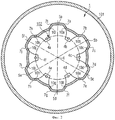
Фигура 2 показывает поперечное сечение через устройство отклонения потока 1, а также герметизирующий корпус 101.Figure 2 shows a cross section through a
Устройство отклонения потока 1 имеет в основном круглое поперечное сечение. Внутри него расположены несколько накладок 4а, b, с, d, е, f. Накладки 4a, b, c, d, e, f служат как для механического крепления устройства отклонения потока 1 на размыкающем блоке 102, так и для электрического контактирования размыкающего блока 102. Имеющее цилиндрическую форму основное тело устройства отклонения потока 1 содержит несколько возвышений 5а, b, с, d, е, f. Возвышения 5a, b, c, d, e, f в основном образованы за счет расширения определенных участков боковой поверхности цилиндрического основного тела относительно продольной оси цилиндра 6 радиально наружу. Переходы от первоначальной боковой поверхности цилиндра к радиально наружу расширенным областям образованы наклонными боковыми сторонами 7а, b, с, d, е, f, g, h, i, j, k, l. Боковые стороны 7a, b, с, d, е, f, g, h, i, j, k, l содержат соответственно отверстия истечения 10а, b, с, d, е, f, g, h, i, j, k, l для отклонения по крайней мере части дугогасящего газа, произведенного в размыкающем блоке 102. Каждое отверстие истечения 10а, b, с, d, е, f, g, h, i, j, k, l направляет часть дугогасящего газа в направление оттока. Направления оттока при этом расположены соответственно таким образом, что они направлены вертикально к соответствующим наклонным боковым сторонам 7a, b, c, d, e, f, g, h, i, j, k, l. Направления оттока соответствующих составляющих дугогасящего газа показаны символически на Фигуре 3 стрелками. Вследствие выбранного положения отверстий истечения 10а, b, с, d, e, f, g, h, i, j, k, l друг относительно друга направления оттока двух противоположных отверстий истечения соседних возвышений соответственно пересекаются. За счет этого достигается, что дугогасящий газ хорошо перемешивается после прохождения через соответствующие отверстия истечения. Это перемешивание схематически представлено на Фигуре 3.The
Представленный на Фигуре 4 первый вариант устройства отклонения потока 1а показывает вид сбоку. Одинаково действующие компоновки показаны на фигурах одинаковыми ссылочными позициями. В первом варианте на устройство отклонения потока 1а приформован соединительный патрубок 16 для подключения электрического провода. Первый вариант устройства отклонения потока 1а имеет цилиндрическую основную форму, на боковой поверхности которой расположены несколько возвышений 5a, b, c, d. Возвышения 5a, b, c, d проходят в виде перемычки вдоль аксиального направления. Один конец первого варианта устройства отклонения потока 1а, как во всех описанных вариантах, закрыт для того, чтобы вдуваемый в первом варианте устройства отклонения потока 1а дугогасящий газ мог оттекать через расположенные в возвышениях 5a, b, c, d отверстия истечения 10b, c, d, f. В первом варианте устройства отклонения потока 1а возвышения 5a, b, c, d имеют внешнюю форму усеченных пирамид. В боковых сторонах (гранях) усеченных пирамид расположено множество отверстий истечения 10b, c, d, f. Отверстия истечения 10b, c, d, f в первом варианте устройства отклонения потока 1а выполнены в виде продолговатого отверстия. Может быть предусмотрено, что соответственно два отверстия истечения 10с, d двух соседних возвышений 5b,с соответственно сопоставлены друг с другом лежащими противоположно, и направления оттока непосредственно сопоставленных друг с другом отверстий оттока 10c, d пересекаются. Представленный на Фигуре 5 второй вариант устройства отклонения потока 1b содержит на своей цилиндрической боковой поверхности несколько углублений 11a, b, c, d. В боковых сторонах углублений 11a, b, c, d расположены следующие отверстия истечения 12а, b, с, d, е, f. Направления оттока отверстий истечения 12d, e, непосредственно лежащих друг против друга в одном углублении 11с, направлены так, что они пересекаются друг с другом. Представленный на Фигуре 6 третий вариант устройства отклонения потока 1с показывает в качестве примера другие возможные варианты выполнения возвышений или, соответственно, углублений. Возвышения или, соответственно, углубления на боковой поверхности устройства отклонения потока могут быть расположены во множестве различных форм. Выполнение соответствующих отверстий истечения может быть при этом очень различным, например круглым, овальным или других подходящих форм, и, например, в виде вертикальных или наклонных сверленых отверстий/фрезерований. Если сверленые отверстия/фрезерования введены в боковую поверхность устройства отклонения потока под тупым или острым углом, то эта "наклонность" обуславливает то, что независимо от выполнения боковой поверхности отверстия истечения позволяют дугогасящему газу оттекать в определенных направлениях истечения. Наряду с описанными возвышениями или, соответственно, углублениями, имеющими форму усеченных пирамид, предпочтительным образом могут быть использованы также другие формы. Выгодными формами являются, например, форма шарового сегмента 13а, b, усеченного тетраэдра 14 или иначе выполненных многоугольных тел 15. Для достижения выгодной диэлектрической конфигурации кромки тел и переходы кромок тел к другим поверхностям снабжены скруглениями.The first embodiment of the
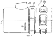
Представленный на Фигуре 7 четвертый вариант устройства отклонения потока 1d содержит в своей боковой поверхности возвышение 17, проходящее кольцееобразно вокруг аксиального направления, а также несколько возвышений, которые образуют кольцееобразное возвышение 17а с прерываниями. На боковых сторонах возвышений 17, 17а расположены отверстия истечения 19a, b, c, d, e, f. Направления истечения отверстий истечения 19а, b, с, d, e, f проходят в аксиальном направлении, причем направления истечения соответственно сопоставленных друг с другом отверстий истечения 19a, f; 19b, e; 19с, d пересекаются. В видоизмененных формах для достижения одинакового действия вместо возвышений на направлении оттока 1d могут быть предусмотрены углубления или отверстия истечения могут быть ориентированы под углом к окружающей их поверхности.The fourth embodiment of the
Для дополнительного завихрения рабочего газа, выступающего из выходных отверстий, с ними могут сопоставляться дополнительные завихряющие тела или отражательные поверхности, которые оказывают влияние на направление дугогасящего газа. Например, на Фигуре 7 представлено входящее в газовый поток завихряющее тело 18.For additional swirling of the working gas protruding from the outlet openings, additional swirling bodies or reflective surfaces can be associated with them, which affect the direction of the extinguishing gas. For example, Figure 7 shows the swirling
Независимо от отдельных вариантов устройства отклонения потока все описанные возвышения являются выполнимыми так же, как и соответствующие углубления, и наоборот и комбинируемыми с завихряющими телами или отражательными поверхностями.Regardless of the individual variants of the flow deflection device, all described elevations are feasible in the same way as the corresponding recesses, and vice versa, and are combined with swirling bodies or reflective surfaces.
Claims (7)
Applications Claiming Priority (2)
| Application Number | Priority Date | Filing Date | Title |
|---|---|---|---|
| DE10156535.6 | 2001-11-14 | ||
| DE10156535A DE10156535C1 (en) | 2001-11-14 | 2001-11-14 | breakers |
Publications (2)
| Publication Number | Publication Date |
|---|---|
| RU2004117866A RU2004117866A (en) | 2006-01-10 |
| RU2293393C2 true RU2293393C2 (en) | 2007-02-10 |
Family
ID=7706112
Family Applications (1)
| Application Number | Title | Priority Date | Filing Date |
|---|---|---|---|
| RU2004117866/09A RU2293393C2 (en) | 2001-11-14 | 2002-10-29 | Force switch |
Country Status (5)
| Country | Link |
|---|---|
| US (1) | US7022922B2 (en) |
| EP (1) | EP1444713B2 (en) |
| DE (2) | DE10156535C1 (en) |
| RU (1) | RU2293393C2 (en) |
| WO (1) | WO2003046939A1 (en) |
Cited By (2)
| Publication number | Priority date | Publication date | Assignee | Title |
|---|---|---|---|---|
| US8399791B2 (en) | 2007-12-19 | 2013-03-19 | Siemens Aktiengesellschaft | Interrupter arrangement having a movable switching tube |
| RU2633514C2 (en) * | 2015-01-22 | 2017-10-13 | ЭлЭсАйЭс КО., ЛТД. | Moulded case circuit breakers |
Families Citing this family (15)
| Publication number | Priority date | Publication date | Assignee | Title |
|---|---|---|---|---|
| ATE388478T1 (en) † | 2002-09-24 | 2008-03-15 | Abb Schweiz Ag | CIRCUIT BREAKER |
| EP1605485B1 (en) * | 2004-06-07 | 2007-08-08 | ABB Technology AG | Circuit breaker |
| CN101120423B (en) * | 2004-12-24 | 2010-06-23 | Abb技术有限公司 | Generator switch having improved switching capacity |
| JP4806534B2 (en) * | 2005-03-31 | 2011-11-02 | カヤバ工業株式会社 | Closing processing method and closing processing machine |
| DE502005009041D1 (en) * | 2005-09-26 | 2010-04-01 | Abb Technology Ag | High voltage switch with improved switching capacity |
| EP1930929B2 (en) † | 2006-12-06 | 2013-01-30 | Abb Research Ltd. | High-tension circuit breaker with a metal tank filled with dielectric gas |
| FR2966972B1 (en) * | 2010-10-27 | 2013-07-19 | Areva T & D Sas | METALLIC ENVELOPE ELECTRICAL EQUIPMENT COMPRISING AT LEAST ONE PARE-EFFLUVE HOOD PROVIDING CONVICTIVE EXCHANGES |
| DE102011083588A1 (en) * | 2011-09-28 | 2013-03-28 | Siemens Aktiengesellschaft | An arrangement comprising a circuit breaker breaker unit |
| DE102012208140A1 (en) * | 2012-05-15 | 2013-11-21 | Siemens Aktiengesellschaft | Electrical contact arrangement |
| DE102013010124A1 (en) * | 2013-06-18 | 2014-12-18 | Abb Technology Ag | Switching chamber for a gas-insulated circuit breaker |
| CA2956733C (en) | 2014-08-15 | 2022-08-23 | Vittorio SCIPOLO | System and method for analyzing dusty industrial off-gas chemistry |
| FR3030869B1 (en) * | 2014-12-19 | 2017-02-10 | Alstom Technology Ltd | CIRCUIT BREAKER COMPRISING AN OBTURABLE OPENING GAS COVER |
| CN109196615B (en) * | 2016-03-24 | 2020-12-22 | Abb电网瑞士股份公司 | Electric circuit breaker device |
| JP6659864B2 (en) * | 2016-10-06 | 2020-03-04 | 株式会社東芝 | Gas circuit breaker |
| EP3503153B1 (en) * | 2017-12-22 | 2021-09-01 | ABB Power Grids Switzerland AG | Gas-insulated high or medium voltage circuit breaker |
Family Cites Families (30)
| Publication number | Priority date | Publication date | Assignee | Title |
|---|---|---|---|---|
| US2511597A (en) * | 1947-04-30 | 1950-06-13 | Joseph P Marx | Muffler with cup-shaped baffle |
| DE1889068U (en) † | 1964-01-18 | 1964-03-12 | Concordia Maschinen Und Elek Z | PIPE SLOT CHAMBER WITH COOLING DEVICE. |
| SE372652B (en) * | 1971-07-30 | 1974-12-23 | Magrini Fab Riun Scarpa | |
| DE2209287C3 (en) * | 1972-02-22 | 1974-12-12 | Siemens Ag, 1000 Berlin Und 8000 Muenchen | Electric pressure gas switch |
| US4000387A (en) * | 1974-05-13 | 1976-12-28 | Westinghouse Electric Corporation | Puffer-type gas circuit-interrupter |
| US4328403A (en) * | 1977-02-15 | 1982-05-04 | Westinghouse Electric Corp. | Single barrel puffer circuit interrupter |
| CH625908A5 (en) * | 1978-03-30 | 1981-10-15 | Sprecher & Schuh Ag | |
| US4276456A (en) * | 1978-10-23 | 1981-06-30 | Westinghouse Electric Corp. | Double-flow puffer-type compressed-gas circuit-interrupter |
| US4291208A (en) * | 1978-11-24 | 1981-09-22 | Westinghouse Electric Corp. | Gas-insulated circuit-interrupter having improved insulating nozzle |
| CH645753A5 (en) † | 1979-05-22 | 1984-10-15 | Sprecher & Schuh Ag | Gas-blast circuit breaker |
| CH643087A5 (en) * | 1979-11-30 | 1984-05-15 | Sprecher & Schuh Ag | Gas-blast circuit breaker |
| DE3107525C2 (en) * | 1980-02-28 | 1994-09-22 | Mitsubishi Electric Corp | Pressurized gas circuit breaker |
| JPS5871524A (en) * | 1981-06-23 | 1983-04-28 | 株式会社東芝 | Buffer type gas breaker |
| EP0075668B1 (en) * | 1981-09-30 | 1987-01-07 | Sprecher Energie AG | Compressed-gas circuit breaker |
| US4426561A (en) * | 1982-01-19 | 1984-01-17 | Westinghouse Electric Corp. | Puffer-type compressed-gas circuit-interrupter |
| JPS6020111A (en) | 1983-07-14 | 1985-02-01 | Fuji Electric Corp Res & Dev Ltd | Distance measuring device |
| DE19526805A1 (en) † | 1995-07-13 | 1997-01-16 | Siemens Ag | High-voltage circuit breaker with an insulating body |
| DE19627098A1 (en) † | 1996-07-05 | 1998-01-08 | Asea Brown Boveri | Circuit breaker |
| DE19641550A1 (en) † | 1996-10-09 | 1998-04-16 | Asea Brown Boveri | Circuit breaker |
| US6757009B1 (en) | 1997-06-11 | 2004-06-29 | Eaton Corporation | Apparatus for detecting the presence of an occupant in a motor vehicle |
| JP4174094B2 (en) † | 1998-01-29 | 2008-10-29 | 株式会社東芝 | Gas circuit breaker |
| JP4172554B2 (en) | 1998-03-12 | 2008-10-29 | 富士重工業株式会社 | Stereo camera adjustment device |
| DE19832709C5 (en) * | 1998-07-14 | 2006-05-11 | Siemens Ag | High voltage circuit breaker with one interrupter unit |
| DE19850395A1 (en) † | 1998-11-02 | 2000-05-04 | Asea Brown Boveri | Power switch for power station, distribution station, has gas channel with internal and external sections connected to intake |
| DE19852653A1 (en) | 1998-11-16 | 2000-05-18 | Bosch Gmbh Robert | Device for detecting the occupancy of a vehicle seat |
| DE19928078A1 (en) † | 1999-06-11 | 2000-12-14 | Siemens Ag | High-voltage (HV) circuit-breaker with diffusor channel |
| DE19928080C5 (en) † | 1999-06-11 | 2006-11-16 | Siemens Ag | High voltage circuit breaker with a discharge channel |
| JP3587506B2 (en) | 1999-08-30 | 2004-11-10 | 富士重工業株式会社 | Stereo camera adjustment device |
| JP3261115B2 (en) | 1999-09-22 | 2002-02-25 | 富士重工業株式会社 | Stereo image processing device |
| DE19953560C1 (en) * | 1999-11-03 | 2001-06-07 | Siemens Ag | Pressurized gas circuit breaker |
-
2001
- 2001-11-14 DE DE10156535A patent/DE10156535C1/en not_active Expired - Fee Related
-
2002
- 2002-10-29 EP EP02803738A patent/EP1444713B2/en not_active Expired - Lifetime
- 2002-10-29 WO PCT/DE2002/004061 patent/WO2003046939A1/en active IP Right Grant
- 2002-10-29 DE DE50202588T patent/DE50202588D1/en not_active Expired - Lifetime
- 2002-10-29 US US10/495,454 patent/US7022922B2/en not_active Expired - Fee Related
- 2002-10-29 RU RU2004117866/09A patent/RU2293393C2/en not_active IP Right Cessation
Cited By (3)
| Publication number | Priority date | Publication date | Assignee | Title |
|---|---|---|---|---|
| US8399791B2 (en) | 2007-12-19 | 2013-03-19 | Siemens Aktiengesellschaft | Interrupter arrangement having a movable switching tube |
| RU2480857C2 (en) * | 2007-12-19 | 2013-04-27 | Сименс Акциенгезелльшафт | Breaker system with movable switching pipe |
| RU2633514C2 (en) * | 2015-01-22 | 2017-10-13 | ЭлЭсАйЭс КО., ЛТД. | Moulded case circuit breakers |
Also Published As
| Publication number | Publication date |
|---|---|
| US20040256361A1 (en) | 2004-12-23 |
| RU2004117866A (en) | 2006-01-10 |
| EP1444713B2 (en) | 2009-11-11 |
| WO2003046939A1 (en) | 2003-06-05 |
| EP1444713B1 (en) | 2005-03-23 |
| US7022922B2 (en) | 2006-04-04 |
| EP1444713A1 (en) | 2004-08-11 |
| DE50202588D1 (en) | 2005-04-28 |
| DE10156535C1 (en) | 2003-06-26 |
Similar Documents
| Publication | Publication Date | Title |
|---|---|---|
| RU2293393C2 (en) | Force switch | |
| US8389886B2 (en) | High-voltage circuit breaker with improved circuit breaker rating | |
| US7202435B2 (en) | Circuit-breaker | |
| JP2947982B2 (en) | Self-extinguishing expansion circuit breaker | |
| RU2608174C2 (en) | Device comprising circuit breaker unit of power switch | |
| JP4643634B2 (en) | Circuit breaker | |
| RU2309478C2 (en) | High-voltage power switch disconnecting unit | |
| JPH04253129A (en) | Circuit breaker | |
| US8502101B2 (en) | Circuit breaker | |
| KR100498833B1 (en) | Power breaker | |
| US6717791B1 (en) | High-voltage circuit breaker with interrupter unit | |
| JP2012517679A (en) | Switchgear with switching path | |
| CN110088868B (en) | Electrical switching device | |
| JP5218449B2 (en) | Gas circuit breaker | |
| JPH0572690B2 (en) | ||
| EP3248203B1 (en) | Exhaust diffuser for a gas-insulated high voltage circuit breaker | |
| RU2342729C1 (en) | Method for exhaust gas cooling in electric switch and electric switch | |
| EP3422381B1 (en) | Gas-insulated load break switch and switchgear comprising a gas-insulated load break switch | |
| EP2360707B1 (en) | Gas mixing enhancement for self-blast circuit breakers | |
| CN216389181U (en) | Hot gas flow exhaust device for arc extinguish chamber, arc extinguish chamber and gas insulated switch | |
| CN113192778B (en) | Hot gas flow exhaust device for arc extinguish chamber, arc extinguish chamber and gas insulated switch | |
| US9396891B2 (en) | Switchgear arrangement | |
| JP3239773U (en) | Circuit breaker with improved exhaust cooling | |
| RU2226303C1 (en) | Sulfur hexafluoride load-breaking isolator | |
| RU2140684C1 (en) | Arc-control device of autocompression gas- filled high-voltage circuit breaker |
Legal Events
| Date | Code | Title | Description |
|---|---|---|---|
| QB4A | Licence on use of patent |
Free format text: LICENCE Effective date: 20120807 |
|
| MM4A | The patent is invalid due to non-payment of fees |
Effective date: 20171030 |