RU2292467C2 - Muffler of internal combustion engine - Google Patents
Muffler of internal combustion engine Download PDFInfo
- Publication number
- RU2292467C2 RU2292467C2 RU2004133820/06A RU2004133820A RU2292467C2 RU 2292467 C2 RU2292467 C2 RU 2292467C2 RU 2004133820/06 A RU2004133820/06 A RU 2004133820/06A RU 2004133820 A RU2004133820 A RU 2004133820A RU 2292467 C2 RU2292467 C2 RU 2292467C2
- Authority
- RU
- Russia
- Prior art keywords
- cross
- perforated shell
- silencer
- internal combustion
- combustion engine
- Prior art date
Links
- 238000002485 combustion reaction Methods 0.000 title claims abstract description 15
- 239000011358 absorbing material Substances 0.000 claims abstract description 15
- 238000005192 partition Methods 0.000 claims abstract description 5
- 230000003584 silencer Effects 0.000 claims description 20
- 239000011521 glass Substances 0.000 claims description 4
- 229920002748 Basalt fiber Polymers 0.000 claims description 2
- 239000000835 fiber Substances 0.000 claims description 2
- 239000003365 glass fiber Substances 0.000 claims description 2
- 239000002184 metal Substances 0.000 claims description 2
- 239000002557 mineral fiber Substances 0.000 claims description 2
- 229920006254 polymer film Polymers 0.000 claims description 2
- 235000019353 potassium silicate Nutrition 0.000 claims description 2
- 241000826860 Trapezium Species 0.000 claims 1
- 238000013016 damping Methods 0.000 abstract description 2
- 230000000694 effects Effects 0.000 abstract description 2
- 238000011089 mechanical engineering Methods 0.000 abstract description 2
- 239000000126 substance Substances 0.000 abstract 1
- 239000007789 gas Substances 0.000 description 6
- 230000001629 suppression Effects 0.000 description 4
- 238000010521 absorption reaction Methods 0.000 description 3
- 239000006096 absorbing agent Substances 0.000 description 1
- 230000005540 biological transmission Effects 0.000 description 1
- 230000015572 biosynthetic process Effects 0.000 description 1
Images

Landscapes
- Exhaust Silencers (AREA)
Abstract
Description
Изобретение относится к машиностроению и может быть использовано для снижения уровня шума отработанных газов в качестве глушителя шума выпуска двигателя внутреннего сгорания.The invention relates to mechanical engineering and can be used to reduce the noise level of exhaust gases as a silencer for the exhaust noise of an internal combustion engine.
Известен глушитель шума выпуска двигателя внутреннего сгорания (ДВС) (патент США №4834214, кл. F01N 1/10, опубл. 1989 г.), содержащий корпус с боковыми стенками, с установленными в нем входным и выходным патрубками диаметром d, взаимодействующие с перфорированной оболочкой, поперечное сечение которой выполнено в виде звезды, пространство между корпусом и перфорированной оболочкой заполнено звукопоглощающим материалом.Known silencer exhaust release of an internal combustion engine (ICE) (US patent No. 4834214, class F01N 1/10, publ. 1989), comprising a housing with side walls, with installed in it inlet and outlet pipes with a diameter of d, interacting with perforated the shell, the cross section of which is made in the form of a star, the space between the body and the perforated shell is filled with sound-absorbing material.
Известное устройство недостаточно эффективно в работе, поскольку не обеспечивает снижение уровня шума в широкополосном диапазоне частот.The known device is not efficient enough to work, because it does not reduce noise in the broadband frequency range.
Задачей настоящего изобретения является разработка глушителя, обеспечивающего возможность регулирования параметров шумоглушения при простой конструкции глушителя.The objective of the present invention is to develop a silencer, providing the ability to control the parameters of sound attenuation with a simple design of the silencer.
Технический результат состоит в повышении эффективности звукоподавления глушителя в низкочастотном и высокочастотном диапазонах звуковых частот при низком противодавлении за счет увеличения площади контакта шумовых волн со звукопоглощающим материалом.The technical result consists in increasing the sound suppression efficiency of the muffler in the low-frequency and high-frequency ranges of sound frequencies with low backpressure due to an increase in the contact area of noise waves with sound-absorbing material.
Результат достигается тем, что в глушителе шума выпуска двигателя внутреннего сгорания, содержащем корпус с боковыми стенками, с установленными в нем входным и выходным патрубками диаметром d, перфорированную оболочку, поперечное сечение которой выполнено в виде звезды, пространство между корпусом и перфорированной оболочкой заполнено звукопоглощающим материалом, в корпусе расположена перегородка, разделяющая его по длине на две камеры, причем ширина поперечного сечения корпуса S=(2,5-12,0)d, высота поперечного сечения корпуса Н=(0,4-1,0)S, длина корпуса L=(4,0-26,0)d, длина первой камеры L1=(0,56-0,59)L, длина второй камеры L2=(0,41-0,44)L, длина входного патрубка L3, длина выходного патрубка L4, длина перфорированной оболочки L5=(1,0-0,2)L, и тем, что ось симметрии поперечного сечения перфорированной оболочки расположена в точке пересечения осей симметрии поперечного сечения корпуса глушителя, и тем, что поперечные сечения отдельных лучей перфорированной оболочки выполнены в виде треугольников, основания которых окружают точку оси симметрии, и тем, что поперечные сечения отдельных лучей перфорированной оболочки выполнены в виде трапеций, большие основания которых окружают точку оси симметрии, и тем, что поперечные сечения отдельных лучей перфорированной оболочки выполнены в виде прямоугольников, одни из оснований которых окружают точку оси симметрии, и тем, что поперечные сечения лучей перфорированной оболочки выполнены в виде криволинейных фигур, основания которых окружают точку оси симметрии, и тем, что поперечные сечения лучей перфорированной оболочки выполнены в виде треугольников и/или в виде трапеций, и/или в виде прямоугольников, и/или в виде криволинейных фигур, и тем, что отношение суммарного периметра поперечного сечения перфорированной оболочки к ее площади составляет К=(4,0-12,5)1/d, и тем, что угол между лучами поперечного сечения перфорированной оболочки составляет величину (0,9-1,1)(360°/n), где n - число лучей от 1 до 8, и тем, что звукопоглощающий материал выполнен в виде стеклянного волокна и/или базальтового волокна и/или высокотемпературного минерального волокна, и/или металлического волокна, и/или стеклянного холста, и/или стеклянной сетки, и/или полимерной пленки, и/или жидкого стекла.The result is achieved in that in the exhaust silencer of the internal combustion engine comprising a housing with side walls, with inlet and outlet nozzles of diameter d installed therein, a perforated shell, the cross section of which is made in the form of a star, the space between the body and the perforated shell is filled with sound-absorbing material , a partition is located in the casing, dividing it along the length into two chambers, the cross-sectional width of the casing S = (2.5-12.0) d, the cross-sectional height of the casing N = (0.4-1.0) S, length and the housing L = (4.0-26.0) d, the length of the first chamber L1 = (0.56-0.59) L, the length of the second chamber L2 = (0.41-0.44) L, the length of the inlet pipe L3, the length of the outlet pipe L4, the length of the perforated shell L5 = (1.0-0.2) L, and the fact that the axis of symmetry of the cross section of the perforated shell is located at the point of intersection of the axes of symmetry of the cross section of the silencer body, and the cross sections individual rays of the perforated shell are made in the form of triangles, the bases of which surround the point of the axis of symmetry, and the fact that the cross sections of the individual rays of the perforated the shells are made in the form of trapezoids, the large bases of which surround the point of the axis of symmetry, and the fact that the cross sections of the individual rays of the perforated shell are made in the form of rectangles, one of the bases of which surround the point of the axis of symmetry, and the cross sections of the rays of the perforated shell are made in the form curvilinear figures, the bases of which surround the point of the axis of symmetry, and the fact that the cross sections of the rays of the perforated shell are made in the form of triangles and / or in the form of trapezoidal shapes, and / or in the form of a rectangle s, and / or in the form of curvilinear figures, and the fact that the ratio of the total perimeter of the cross section of the perforated shell to its area is K = (4.0-12.5) 1 / d, and the angle between the rays of the cross section of the perforated the sheath is a value of (0.9-1.1) (360 ° / n), where n is the number of rays from 1 to 8, and the fact that the sound-absorbing material is made in the form of glass fiber and / or basalt fiber and / or high-temperature mineral fiber and / or metal fiber and / or glass canvas and / or glass mesh and / or polymer film , and / or liquid glass.
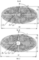
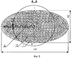
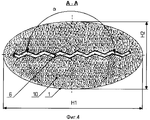
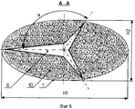
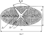
Сущность изобретения поясняется чертежами, на который изображены на фиг.1 - условный разрез глушителя, его вид сбоку, на фиг.2 - разрез по А-А и Б-Б глушителя с 4-лучевой перфорированной оболочкой с лучами прямоугольной формы, на фиг.3 - пример выполнения однолучевой перфорированной оболочки с лучом криволинейной формы, на фиг.4 - пример выполнения двухлучевой перфорированной оболочки с лучами криволинейной формы, на фиг.5 - пример выполнения трехлучевой перфорированной оболочки с лучами треугольной формы, на фиг.6 - пример выполнения пятилучевой перфорированной оболочки с лучами в форме трапеций (усеченные треугольники), на фиг.7 - пример выполнения шестилучевой перфорированной оболочки с лучами всех вышеперечисленных форм.The invention is illustrated by drawings, which depict in Fig.1 is a conditional section of a muffler, its side view, Fig.2 is a section along aa and bb of a muffler with a 4-beam perforated shell with rectangular beams, in fig. 3 is an example of a single-beam perforated shell with a curved beam, FIG. 4 is an example of a two-beam perforated shell with curved beams, FIG. 5 is an example of a three-beam perforated shell with triangular beams, and FIG. 6 is an example of a five-beam perforated shell of rays in the form of trapezoids (truncated triangle), 7 - an exemplary embodiment of a six-perforated shell with rays of all the above forms.
Глушитель содержит корпус 1, ширина поперечного сечения которого S=(2,5-12,0)d, высота поперечного сечения - Н=(0,4-1,0)S, длина корпуса - L=(4,0-26,0)d, боковые стенки 2, 3, входной патрубок 4 диаметром d, выходной патрубок 5 диаметром d, перфорированную оболочку 6 длиной L5=(1,0-0,2)L, поперечное сечение перфорированной оболочки выполнено в виде звезды, корпус 1 разделен перегородкой 7 на камеру 8 длиной L1=(0,56-0,59)L и камеру 9 длиной L2=(0,41-0,44)L, весь объем между корпусом и перфорированной оболочкой заполнено звукопоглощающим материалом 10.The silencer comprises a
Глушитель работает следующим образом.The muffler works as follows.
При работе двигателя поток выхлопных газов через входной патрубок 4 поступает в место его сопряжения с перфорированной оболочкой 6, выполненной в форме звезды, конструкция которой обеспечивает формирование щелевого звездообразного канала в поперечном сечении оболочки. В месте сопряжения происходит перераспределение прохождения газового потока выхлопа, который движется далее вдоль глушителя и части перфорированной оболочки 6 вместе со звуковыми волнами в направлении выходного патрубка 5 по внутреннему щелевому каналу, образованному частью перфорированной оболочки 6 в форме звезды. По мере продвижения выхлопных газов выпуска и звуковых волн вдоль перфорированной оболочки 6 происходит взаимодействие звуковых волн выпуска через перфорацию оболочки 6 со звукопоглощающим материалом 10, находящимся в камерах 8, 9, образованных перегородкой 7. При этом, чем больше суммарная площадь соприкосновения движущихся звуковых волн со звукопоглощающим материалом 10, тем выше эффективность глушителя. Далее, после прохождения газов и шума выхлопа вдоль перфорированной оболочки 6 поток поступает в место сопряжения перфорированной оболочки 6 с выходным патрубком 5. В этом месте сопряжения происходит вторичное перераспределение прохождения газового потока выхлопа и уже заглушенного шума, которые движутся далее через выходной патрубок 5 на выход из глушителя.When the engine is running, the exhaust stream through the inlet pipe 4 enters its interface with the
Эффективное глушение шума в широком диапазоне частот звука достигается совместным воздействием на шум объемов камер 8 и 9, имеющих оптимально подобранные соотношения длин камер и звукопоглотителя, площадь соприкосновения с которым максимизирована конструкцией перфорированной оболочки 6 в форме звезды, а значит, максимизирована и его звукопоглощающая способность. Известно, что звукопоглощающая способность звукопоглощающих материалов высока в области высоких частот звука и недостаточна в области низких частот при использовании их в конструкциях глушителей выхлопа (§29, 30, с.174-177, Зинченко В.И. Шум судовых двигателей, М., Судпромгиз, 1957). При этом их частотная характеристика в области высоких частот звукопоглощения имеет достаточно стабильный характер. Также известно, что для подавления шумов в области низких частот могут быть подобраны объемы расширительных камер (§29, 31, 32, с.174-187, Зинченко В.И. Шум судовых двигателей, М., Судпромгиз, 1957). Однако частотная характеристика подавления шума такими камерами представляет собой чередование областей максимального подавления и полного пропускания шума в различных областях частотного диапазона. Совместное использование подавления шума с помощью звукопоглощения с использованием звукопоглощающего материала и вариаций объемами расширительных камер позволяет получать оптимальную характеристику подавления шума в широком диапазоне частот (§29, с.174-175, Зинченко В.И. Шум судовых двигателей, М., Судпромгиз, 1957). При этом использование звукопоглощающих каналов перфорированной оболочки 6 в форме звезды является прямоточным для прохождения газового потока выхлопа, что минимизирует газодинамическое сопротивление глушителя и одновременно максимизирует эффективность звукопоглощающего материала.Effective damping of noise in a wide range of sound frequencies is achieved by joint exposure of the volumes of chambers 8 and 9 to the noise, having optimally selected ratios of the lengths of the chambers and the sound absorber, the contact area with which is maximized by the design of the
Изобретение позволяет повысить эффективность звукоподавления глушителя в низкочастотном и высокочастотном диапазонах звуковых частот при низком противодавлении за счет увеличения площади контакта шумовых волн со звукопоглощающим материалом.EFFECT: invention makes it possible to increase the sound suppression efficiency of a muffler in the low-frequency and high-frequency ranges of sound frequencies at a low backpressure due to an increase in the area of contact of noise waves with sound-absorbing material.
Claims (10)
Priority Applications (1)
| Application Number | Priority Date | Filing Date | Title |
|---|---|---|---|
| RU2004133820/06A RU2292467C2 (en) | 2004-11-19 | 2004-11-19 | Muffler of internal combustion engine |
Applications Claiming Priority (1)
| Application Number | Priority Date | Filing Date | Title |
|---|---|---|---|
| RU2004133820/06A RU2292467C2 (en) | 2004-11-19 | 2004-11-19 | Muffler of internal combustion engine |
Publications (2)
| Publication Number | Publication Date |
|---|---|
| RU2004133820A RU2004133820A (en) | 2006-05-20 |
| RU2292467C2 true RU2292467C2 (en) | 2007-01-27 |
Family
ID=36657932
Family Applications (1)
| Application Number | Title | Priority Date | Filing Date |
|---|---|---|---|
| RU2004133820/06A RU2292467C2 (en) | 2004-11-19 | 2004-11-19 | Muffler of internal combustion engine |
Country Status (1)
| Country | Link |
|---|---|
| RU (1) | RU2292467C2 (en) |
Citations (3)
| Publication number | Priority date | Publication date | Assignee | Title |
|---|---|---|---|---|
| US1934462A (en) * | 1930-10-30 | 1933-11-07 | Burgess Lab Inc C F | Muffler |
| US4834214A (en) * | 1987-06-08 | 1989-05-30 | Feuling James J | Muffler for an internal combustion engine |
| GB2256006A (en) * | 1991-05-21 | 1992-11-25 | Harbury Holdings Inc | Exhaust silencer. |
-
2004
- 2004-11-19 RU RU2004133820/06A patent/RU2292467C2/en not_active IP Right Cessation
Patent Citations (3)
| Publication number | Priority date | Publication date | Assignee | Title |
|---|---|---|---|---|
| US1934462A (en) * | 1930-10-30 | 1933-11-07 | Burgess Lab Inc C F | Muffler |
| US4834214A (en) * | 1987-06-08 | 1989-05-30 | Feuling James J | Muffler for an internal combustion engine |
| GB2256006A (en) * | 1991-05-21 | 1992-11-25 | Harbury Holdings Inc | Exhaust silencer. |
Also Published As
| Publication number | Publication date |
|---|---|
| RU2004133820A (en) | 2006-05-20 |
Similar Documents
| Publication | Publication Date | Title |
|---|---|---|
| US6415887B1 (en) | Refractive wave muffler | |
| IL144189A (en) | Sound-attenuating muffler for internal combustion engine | |
| RU2292467C2 (en) | Muffler of internal combustion engine | |
| CA2525477A1 (en) | Sound-attenuating muffler having reduced back pressure | |
| RU2276735C1 (en) | Multichamber muffler | |
| WO1994018438A1 (en) | A silencer | |
| RU2280175C1 (en) | Chamber noise silencer | |
| RU11834U1 (en) | INTERNAL COMBUSTION ENGINE EXHAUST SILENCER | |
| RU185332U1 (en) | SILENCER OF EXHAUST GAS OF INTERNAL COMBUSTION ENGINE | |
| RU2241126C1 (en) | Internal combustion engine muffler | |
| RU2224897C2 (en) | Muffler for internal combustion engine | |
| RU2282730C2 (en) | Exhaust muffler of internal combustion engine | |
| RU2015357C1 (en) | Exhaust silencer for internal combustion engine | |
| RU2085752C1 (en) | Noise silencer | |
| RU2134800C1 (en) | Exhaust muffler of internal combustion engine | |
| RU68596U1 (en) | INTERNAL COMBUSTION ENGINE RELEASE SILENCER | |
| RU2065064C1 (en) | Exhaust muffler for internal combustion engine | |
| SU1613666A1 (en) | I.c.engine exhaust muffler | |
| RU33407U1 (en) | Combustion exhaust silencer | |
| RU195483U1 (en) | Muffler | |
| RU2253806C1 (en) | Noise silencer | |
| RU2298673C1 (en) | Chamber noise silencer | |
| RU2272156C1 (en) | Muffler of internal combustion engine | |
| SU1629575A1 (en) | Internal combustion engine muffler | |
| RU2183277C2 (en) | Muffler for internal combustion engine |
Legal Events
| Date | Code | Title | Description |
|---|---|---|---|
| MM4A | The patent is invalid due to non-payment of fees |
Effective date: 20101120 |
|
| NF4A | Reinstatement of patent |
Effective date: 20120510 |
|
| PC41 | Official registration of the transfer of exclusive right |
Effective date: 20120608 |
|
| MM4A | The patent is invalid due to non-payment of fees |
Effective date: 20141120 |