RU2292103C1 - Continuous stimulated-scattering combination laser - Google Patents
Continuous stimulated-scattering combination laser Download PDFInfo
- Publication number
- RU2292103C1 RU2292103C1 RU2005110806/28A RU2005110806A RU2292103C1 RU 2292103 C1 RU2292103 C1 RU 2292103C1 RU 2005110806/28 A RU2005110806/28 A RU 2005110806/28A RU 2005110806 A RU2005110806 A RU 2005110806A RU 2292103 C1 RU2292103 C1 RU 2292103C1
- Authority
- RU
- Russia
- Prior art keywords
- radiation
- resonator
- raman
- laser according
- wavelength
- Prior art date
Links
- 230000005855 radiation Effects 0.000 claims abstract description 86
- 230000005284 excitation Effects 0.000 claims abstract description 11
- 239000007788 liquid Substances 0.000 claims abstract description 7
- 238000001069 Raman spectroscopy Methods 0.000 claims description 52
- 239000007789 gas Substances 0.000 claims description 8
- XKRFYHLGVUSROY-UHFFFAOYSA-N Argon Chemical compound [Ar] XKRFYHLGVUSROY-UHFFFAOYSA-N 0.000 claims description 6
- 229910052786 argon Inorganic materials 0.000 claims description 3
- 238000000576 coating method Methods 0.000 claims description 2
- 230000000694 effects Effects 0.000 abstract description 6
- 238000005086 pumping Methods 0.000 abstract description 4
- 239000003814 drug Substances 0.000 abstract description 3
- 238000004611 spectroscopical analysis Methods 0.000 abstract description 3
- 239000000126 substance Substances 0.000 abstract 1
- 239000013078 crystal Substances 0.000 description 18
- IWOUKMZUPDVPGQ-UHFFFAOYSA-N barium nitrate Chemical compound [Ba+2].[O-][N+]([O-])=O.[O-][N+]([O-])=O IWOUKMZUPDVPGQ-UHFFFAOYSA-N 0.000 description 10
- 230000003595 spectral effect Effects 0.000 description 6
- 125000004122 cyclic group Chemical group 0.000 description 4
- 230000003993 interaction Effects 0.000 description 4
- 238000002176 non-resonance Raman spectroscopy Methods 0.000 description 4
- 230000003287 optical effect Effects 0.000 description 4
- 241001125929 Trisopterus luscus Species 0.000 description 3
- 238000013459 approach Methods 0.000 description 3
- 238000005516 engineering process Methods 0.000 description 3
- 238000000034 method Methods 0.000 description 3
- 238000001228 spectrum Methods 0.000 description 3
- UFHFLCQGNIYNRP-UHFFFAOYSA-N Hydrogen Chemical compound [H][H] UFHFLCQGNIYNRP-UHFFFAOYSA-N 0.000 description 2
- XUIMIQQOPSSXEZ-UHFFFAOYSA-N Silicon Chemical compound [Si] XUIMIQQOPSSXEZ-UHFFFAOYSA-N 0.000 description 2
- 238000010521 absorption reaction Methods 0.000 description 2
- XMPZLAQHPIBDSO-UHFFFAOYSA-N argon dimer Chemical compound [Ar].[Ar] XMPZLAQHPIBDSO-UHFFFAOYSA-N 0.000 description 2
- 239000000835 fiber Substances 0.000 description 2
- 239000001257 hydrogen Substances 0.000 description 2
- 229910052739 hydrogen Inorganic materials 0.000 description 2
- LQNUZADURLCDLV-UHFFFAOYSA-N nitrobenzene Chemical compound [O-][N+](=O)C1=CC=CC=C1 LQNUZADURLCDLV-UHFFFAOYSA-N 0.000 description 2
- 239000013307 optical fiber Substances 0.000 description 2
- 230000008569 process Effects 0.000 description 2
- 239000004065 semiconductor Substances 0.000 description 2
- 229910052710 silicon Inorganic materials 0.000 description 2
- 239000010703 silicon Substances 0.000 description 2
- 230000000638 stimulation Effects 0.000 description 2
- 238000002834 transmittance Methods 0.000 description 2
- 238000009825 accumulation Methods 0.000 description 1
- 238000004458 analytical method Methods 0.000 description 1
- 230000005540 biological transmission Effects 0.000 description 1
- 230000015572 biosynthetic process Effects 0.000 description 1
- 238000006243 chemical reaction Methods 0.000 description 1
- 238000013461 design Methods 0.000 description 1
- 238000011161 development Methods 0.000 description 1
- 238000002474 experimental method Methods 0.000 description 1
- 238000010438 heat treatment Methods 0.000 description 1
- 230000010354 integration Effects 0.000 description 1
- 238000004519 manufacturing process Methods 0.000 description 1
- 229910052754 neon Inorganic materials 0.000 description 1
- GKAOGPIIYCISHV-UHFFFAOYSA-N neon atom Chemical compound [Ne] GKAOGPIIYCISHV-UHFFFAOYSA-N 0.000 description 1
- 230000003071 parasitic effect Effects 0.000 description 1
- 230000009467 reduction Effects 0.000 description 1
- 239000007787 solid Substances 0.000 description 1
- 230000007704 transition Effects 0.000 description 1
Images

Landscapes
- Lasers (AREA)
- Optical Modulation, Optical Deflection, Nonlinear Optics, Optical Demodulation, Optical Logic Elements (AREA)
Abstract
Description
Изобретение относится к области лазерной техники и может быть применено в спектроскопии, лазерной физике, нелинейной оптике, биологии, экологии, медицине и т.д.The invention relates to the field of laser technology and can be applied in spectroscopy, laser physics, nonlinear optics, biology, ecology, medicine, etc.
Вынужденное комбинационное рассеяние (ВКР) является распространенным методом преобразования частоты импульсного лазерного излучения в новые спектральные диапазоны. В настоящее время с помощью импульсной ВКР-генерации возможно перекрытие перестраиваемым лазерным излучением спектрального диапазона от УФ- до ИК-области.Stimulated Raman scattering (SRS) is a common method for converting the frequency of pulsed laser radiation into new spectral ranges. Currently, using pulsed Raman lasing, it is possible to overlap the tunable laser radiation with a spectral range from the UV to the IR region.
Создание ВКР-преобразователей непрерывного лазерного излучения является более сложной проблемой в связи с тем, что для достижения порога ВКР обычно требуются мощности лазерного излучения в киловаттной области. Хотя лазерные системы, производящие киловаттные мощности непрерывного излучения, существуют, их стоимость велика, а распространенность весьма ограничена. Между тем лазерные системы, производящие непрерывное излучение с мощностью 1-10 Вт, обладают умеренной стоимостью и получили широкое распространение. Они используются в спектроскопии, биологии, медицине, различных областях техники. Осуществление ВКР-преобразования частоты излучения таких непрерывных лазеров может значительно расширить диапазон их применения, открыв возможность их использования в не доступных ранее спектральных областях.The creation of SRS converters of continuous laser radiation is a more difficult problem due to the fact that in order to reach the SRS threshold, laser power in the kilowatt region is usually required. Although laser systems producing kilowatt continuous radiation power exist, their cost is high and their distribution is very limited. Meanwhile, laser systems producing continuous radiation with a power of 1-10 W have a moderate cost and are widely used. They are used in spectroscopy, biology, medicine, various fields of technology. The implementation of the Raman conversion of the radiation frequency of such cw lasers can significantly expand the range of their application, opening the possibility of their use in previously unavailable spectral regions.
Известна реализация непрерывного режима ВКР-генерации, использующая эффект резонансного ВКР. Он состоит в том, что если длина волны возбуждающего лазера приближается к длине волны резонансного перехода среды, то коэффициент ВКР усиления среды существенно возрастает. Это позволяет снизить пороговую мощность возбуждения и получить ВКР-генерацию в непрерывном режиме при мощностях ваттного уровня. Примерами такого типа устройств являются непрерывные ВКР-лазеры на NH3 [1], непрерывные ВКР-лазеры на парах Na, работающие вблизи D-линий [2], двухфотонно возбуждаемые непрерывные ВКР-лазеры на парах Rb [3] и ВКР-лазеры на резонансе неона в газоразрядных трубках He-Ne лазеров [4]. Недостатком таких лазеров является необходимость их возбуждения вблизи резонанса, что налагает ограничения как на длины волн лазеров накачки, так и на области их перестройки, резко ограничивая возможность использования резонансного ВКР.A known implementation of the continuous mode of stimulated Raman generation, using the effect of resonant Raman stimulation. It consists in the fact that if the wavelength of the exciting laser approaches the wavelength of the resonant transition of the medium, then the Raman gain of the medium increases significantly. This makes it possible to reduce the threshold excitation power and to obtain Raman generation in a continuous mode at power levels of the watt level. Examples of such devices are cw Raman lasers based on NH 3 [1], cw Raman lasers based on Na pairs operating near the D lines [2], two-photon excited cw Raman lasers based on Rb [3] and Raman lasers using neon resonance in gas-discharge tubes of He-Ne lasers [4]. The disadvantage of such lasers is the need for their excitation near the resonance, which imposes restrictions both on the wavelengths of the pump lasers and on the region of their tuning, sharply limiting the possibility of using resonant stimulated Raman scattering.
Второй тип непрерывных ВКР-лазеров основан на нерезонансном ВКР в очень высокодобротном резонаторе, обеспечивающем накопление излучения на длинах волн накачки и стоксова излучения [5]. Такое устройство состоит из маломощного непрерывного лазера накачки, ВКР-среды, резонатора с высокой добротностью обеспечивающей ВКР при возбуждении указанным непрерывным лазером. Зеркала, образующие резонатор, являются высокоотражающими на длинах волн накачки и первой стоксовой компоненты (R=99.995%). Использование такого высокодобротного на двух длинах волн резонатора позволяет существенно понизить мощность, необходимую для достижения порога, и получить ВКР-генерацию при накачке непрерывным лазером с мощностью несколько мВт. Порог ВКР при этом обратно пропорционален квадрату добротности резонатора. Недостатком такого устройства является необходимость использовать лазер накачки, работающий в одночастотном режиме генерации, что резко снижает его применимость, так как большинство лазеров работает в многочастотных режимах. Кроме того, устройство имеет сложную схему согласования моды излучения лазера накачки с модой ВКР-резонатора, что также затруднено в многочастотном случае. Следует отметить высокую стоимость зеркал с такими коэффициентами отражения. Важной особенностью устройства является то, что используемая газовая среда (водород) и резонаторные зеркала находятся в сосуде высокого давления. Это обеспечивает отсутствие окон в резонаторе и предельно минимизирует резонаторные потери, сводя их, по существу, к потерям на зеркалах. Отсутствие потерь внутри резонатора позволяет в полной мере использовать высокие отражения зеркал для снижения порога ВКР. Потери практически обусловлены пропусканием зеркал, так как потери в газе пренебрежимо малы. В случае же если в резонатор вносится среда в виде кристалла или кюветы с жидкостью, потери в резонаторе будут возрастать за счет отражений на границах поглощения в самих рассеивающих средах, паразитного рассеяния на их неоднородностях. В этом случае добротность резонатора будет существенно падать, использование зеркал с очень высокими коэффициентами отражения становится бесполезным, а порог ВКР будет возрастать.The second type of cw Raman lasers is based on nonresonant Raman scattering in a very high-Q cavity, which ensures the accumulation of radiation at the wavelengths of the pump and Stokes radiation [5]. Such a device consists of a low-power cw pump laser, a Raman medium, and a resonator with high quality factor providing Raman stimulation upon excitation by the cw laser. The mirrors forming the resonator are highly reflective at the wavelengths of the pump and the first Stokes component (R = 99.995%). The use of such a high-Q resonator at two wavelengths allows one to significantly reduce the power required to reach the threshold and to obtain Raman generation when pumped by a cw laser with a power of several mW. The SRS threshold is inversely proportional to the square of the Q factor of the resonator. The disadvantage of this device is the need to use a pump laser operating in the single-frequency generation mode, which sharply reduces its applicability, since most lasers operate in multi-frequency modes. In addition, the device has a complex scheme for matching the radiation mode of the pump laser with the Raman mode, which is also difficult in the multi-frequency case. It should be noted the high cost of mirrors with such reflection coefficients. An important feature of the device is that the used gas medium (hydrogen) and resonator mirrors are located in the pressure vessel. This ensures that there are no windows in the resonator and minimizes resonator losses to a maximum, reducing them, in essence, to losses on the mirrors. The absence of losses inside the resonator allows the full use of high reflection of mirrors to reduce the SRS threshold. Losses are practically caused by transmission of mirrors, since losses in gas are negligible. If the medium is introduced into the resonator in the form of a crystal or a cell with a liquid, the losses in the resonator will increase due to reflections at the absorption boundaries in the scattering media themselves, and parasitic scattering from their inhomogeneities. In this case, the quality factor of the resonator will decrease significantly, the use of mirrors with very high reflection coefficients becomes useless, and the SRS threshold will increase.
Таким образом, задача получения непрерывной генерации в дешевом компактном нерезонансном ВКР-лазере, способном работать на разных видах комбинационно активных сред и использующем для возбуждения излучение умеренной мощности (1-10 Вт) широко распространенных непрерывных серийных лазеров, генерирующих как одночастотное, так и многочастотное излучение, не решена.Thus, the problem of obtaining continuous generation in a low-cost compact non-resonant Raman laser capable of operating on different types of Raman active media and using moderate-power radiation (1-10 W) of widespread continuous serial lasers generating both single-frequency and multi-frequency radiation to excite not resolved.
Наиболее близким к заявляемому является ВКР-лазер на оптическом волокне, например устройство, описанное в [6]. Оно содержит непрерывный лазер накачки и оптическое волокно, помещенное в резонатор. Благодаря большой длине волокна (от 25 до 100 м) и его малому диаметру (до нескольких мкм) оказалось возможным снижение пороговой мощности возбуждения непрерывной ВКР-генерации до 5 Вт. Недостатками такого устройства являются: небольшой спектральный сдвиг в волокне (порядка 440 см-1), возникновение конкурирующей генерации на вынужденном рассеянии Мандельштама-Бриллюэна и относительно большая длина рассеивающей среды, препятствующая снижению габаритов такого устройства. Хотя теоретически уменьшение длины комбинационно-активной среды возможно, ее сокращение, например, от 25 м до 50 см приведет к 50-кратному возрастанию порога ВКР - до 250 Вт, что делает такой подход малоприемлемым.Closest to the claimed is a Raman laser on an optical fiber, for example, the device described in [6]. It contains a cw pump laser and an optical fiber placed in the cavity. Due to the large fiber length (from 25 to 100 m) and its small diameter (to several microns), it was possible to reduce the threshold excitation power of cw Raman generation to 5 watts. The disadvantages of such a device are: a small spectral shift in the fiber (about 440 cm -1 ), the appearance of competing generation on stimulated Mandelstam-Brillouin scattering, and the relatively large length of the scattering medium, which prevents the dimensions of such a device from being reduced. Although theoretically a decrease in the length of the Raman-active medium is possible, its reduction, for example, from 25 m to 50 cm will lead to a 50-fold increase in the SRS threshold - up to 250 W, which makes this approach unacceptable.
Задачей данного изобретения является создание относительно дешевого, компактного непрерывного нерезонансного ВКР-лазера, концепция которого позволяла бы внесение комбинационно активного элемента в виде кристалла, кюветы с жидкостью или газом в резонатор, а также обеспечивала бы возможность преобразования излучения непрерывных лазеров, работающих как в одночастотном, так и в многочастотном режимах.The objective of the invention is to provide a relatively cheap, compact continuous non-resonant Raman laser, the concept of which would allow the introduction of a Raman active element in the form of a crystal, a cuvette with a liquid or gas into the resonator, and would also provide the possibility of converting the radiation from cw lasers operating as in single-frequency, and in multi-frequency modes.
Поставленная задача в непрерывном лазере на вынужденном комбинационном рассеянии, содержащем источник непрерывного излучения накачки и резонатор, образованный входным и выходным зеркалами с размещенной в нем комбинационно активной средой, причем резонатор выполнен с добротностью на длине волны излучения вынужденного комбинационного рассеяния, достаточной для возбуждения последнего в комбинационно активной среде, решена тем, что входное зеркало резонатора выполнено, по существу, прозрачным в диапазоне длин волн излучения накачки, при этом значение пороговой мощности возбуждения ВКР обратно пропорционально первой степени добротности резонатора на длине волны излучения вынужденного комбинационного рассеяния.The stated problem is in a stimulated Raman scattering cw laser containing a source of continuous pump radiation and a resonator formed by input and output mirrors with a Raman active medium placed in it, and the resonator is made with a Q factor at a stimulated Raman scattering radiation wavelength sufficient to excite the latter in Raman active medium, it is decided that the input mirror of the resonator is made essentially transparent in the wavelength range of the pump radiation, n and this threshold value Raman excitation power is inversely proportional to the resonator Q first power at a wavelength of stimulated Raman scattering.
Предпочтительно входное зеркало резонатора может быть выполнено максимально отражающим на длине волны излучения первой стоксовой компоненты, а выходное зеркало резонатора - оптимально отражающим на длине волны излучения первой стоксовой компоненты, при этом резонатор может быть выполнен с добротностью на длине волны излучения второй стоксовой компоненты достаточно низкой, чтобы избежать генерации второй стоксовой компоненты.Preferably, the input mirror of the resonator can be made as reflective as possible at the wavelength of the radiation of the first Stokes component, and the output mirror of the resonator can be optimally reflective at the wavelength of the radiation of the first Stokes component, while the resonator can be made with a quality factor at the radiation wavelength of the second Stokes component, sufficiently low, to avoid generating a second Stokes component.
Резонатор может быть выполнен с добротностью на длине волны излучения второй стоксовой компоненты, достаточной для достижения порога генерации второй стоксовой компоненты, причем входное зеркало выполнено максимально отражающим на длинах волн излучения первой и второй стоксовой компоненты, а выходное выполнено максимально отражающим на длине волны излучения первой стоксовой компоненты и оптимально отражающим на длине волны излучения второй стоксовой компоненты.The resonator can be made with a Q factor at the radiation wavelength of the second Stokes component, sufficient to achieve the generation threshold of the second Stokes component, the input mirror being made as reflective as possible at the radiation wavelengths of the first and second Stokes components, and the output mirror is made as reflective as possible at the radiation wavelength of the first Stokes component components and optimally reflecting at the radiation wavelength of the second Stokes component.
Выходное зеркало может отражать излучение накачки.The output mirror may reflect pump radiation.
Источник непрерывного излучения накачки может излучать как одночастотное, так и многочастотное излучение, в частном случае источником излучения накачки является аргоновый лазер.A source of continuous pump radiation can emit both single-frequency and multi-frequency radiation, in the particular case the source of pump radiation is an argon laser.
Мощность источника излучения накачки выбирают от 0.1 до 10 Вт.The power of the pump radiation source is selected from 0.1 to 10 watts.
Комбинационно активная (ВКР-активная) среда может быть выполнена в виде кюветы с жидкостью или газом, но предпочтительно выполнена твердотельной и может быть выбрана из группы кристаллических сред, включающей Ва(NO3)2, KGd(WO4)2, KY(WO4)2, KYb(WO4)2, BaWO4, YVO4. ВКР-активная среда может также представлять собой полупроводниковый кристалл, например кристалл кремния.The Raman-active (SRS-active) medium can be made in the form of a cuvette with a liquid or gas, but it is preferably solid-state and can be selected from the group of crystalline media, including Ba (NO 3 ) 2 , KGd (WO 4 ) 2 , KY (WO 4 ) 2 , KYb (WO 4 ) 2 , BaWO 4 , YVO 4 . The SRS-active medium may also be a semiconductor crystal, for example a silicon crystal.
Комбинационно-активная среда предпочтительно помещена в корпус, обеспечивающий теплоотвод, который может быть выполнен центрально-симметричным.The combination-active medium is preferably placed in a housing that provides a heat sink, which can be made centrally symmetrical.
На все элементы, расположенные внутри резонатора, нанесены антиотражающие покрытия.All elements located inside the resonator are coated with antireflection coatings.
Т.о. задача решена путем создания резонатора, высокодобротного лишь на длине волны излучения вынужденного комбинационного рассеяния, причем порог ВКР в такой системе будет обратно пропорционален добротности резонатора. В таком случае может быть использована накачка и многочастотными лазерами. Неочевидным является то, что и при использовании относительно короткой ВКР-среды (<10 см) и резонатора, добротного лишь на длине волны излучения вынужденного комбинационного рассеяния, возможно достижение порога непрерывного ВКР до приемлемых мощностей (0.1-10 Вт) за счет увеличения добротности резонатора.T.O. The problem is solved by creating a resonator that is high-Q only at the wavelength of radiation of stimulated Raman scattering, and the SRS threshold in such a system will be inversely proportional to the Q-factor of the resonator. In this case, pumping with multi-frequency lasers can also be used. It is not obvious that when using a relatively short Raman medium (<10 cm) and a resonator that is high-quality only at a wavelength of stimulated Raman scattering radiation, it is possible to reach a threshold for continuous Raman scattering to acceptable powers (0.1-10 W) by increasing the cavity Q .
В принципе, снижение порога ВКР за счет повышения добротности в резонаторе известно. Это используется для снижения порога ВКР-лазеров с импульсной накачкой Однако, насколько нам известно, наименьшая достигнутая в импульсном режиме пороговая мощность ВКР-генерации в высокодобротном резонаторе при использовании кристалла (нитрата бария) составила примерно 500 Вт (8 мкДж при длительности импульса 15 нс) [7], что гораздо больше мощности обычных непрерывных лазеров.In principle, a decrease in the SRS threshold due to an increase in the Q factor in the cavity is known. This is used to lower the threshold of pulse Raman Raman lasers. However, as far as we know, the lowest threshold Raman power achieved in a pulsed mode in a high-Q cavity using a crystal (barium nitrate) was approximately 500 W (8 μJ for a pulse duration of 15 ns) [7], which is much more than the power of conventional cw lasers.
Поэтому неочевидно, что возможно дальнейшее существенное снижение порога в непрерывном режиме до приемлемого уровня мощностей за счет увеличения добротности резонатора. Тем не менее, проведенный нами анализ и эксперимент показывают, что это возможно, т.к. зависимости порога от добротности резонатора в импульсном и непрерывном режимах различны.Therefore, it is not obvious that a further significant decrease in the threshold in continuous mode to an acceptable power level is possible due to an increase in the quality factor of the resonator. Nevertheless, our analysis and experiment show that this is possible, because the dependence of the threshold on the quality factor of the resonator in pulsed and continuous modes is different.
Предположим, что ВКР происходит в стационарном режиме (длительности всех процессов много больше как времени поперечной релаксации среды, так и времени обхода по резонатору), и будем пренебрегать истощением накачки.We assume that SRS occurs in a stationary mode (the duration of all processes is much longer than both the time of transverse relaxation of the medium and the time of going around the cavity), and we will neglect pump depletion.
Тогда для мощности первой стоксовой компоненты можно записать формулу, известную, например, из [5]:Then, for the power of the first Stokes component, we can write a formula known, for example, from [5]:
![]()
![]()
где PS, PP - мощности стоксовой компоненты и накачки внутри резонатора соответственно,where P S , P P are the powers of the Stokes component and the pump inside the resonator, respectively,
t - время,t is the time
GS и LS - усиление и потери на длине волны стоксовой компоненты в единицу времени. GS и LS выражаются как:G S and L S - gain and loss at the wavelength of the Stokes component per unit time. G S and L S are expressed as:
![]()
![]()
где с - скорость света,where c is the speed of light
LC - оптическая длина резонатора,L C is the optical length of the resonator,
Leff - длина взаимодействия,L eff is the interaction length,
g - коэффициент усиления ВКР,g - gain SRS,
Seff - площадь поперечного сечения пучка накачки излучения.S eff is the cross-sectional area of the radiation pump beam.
![]()
![]()
где с - скорость света,where c is the speed of light
LC - оптическая длина резонатора,L C is the optical length of the resonator,
Rin, Rout - коэффициенты отражения входного и выходного зеркал,R in , R out - reflection coefficients of the input and output mirrors,
γ - потери на один проход,γ - loss per pass,
tC - время жизни фотона в резонаторе.t C is the photon lifetime in the cavity.
Поскольку добротность резонатора Q можно выразить как [8]:Since the Q factor of the resonator Q can be expressed as [8]:
![]()
![]()
где ω0 - циклическая частота световых колебаний,where ω 0 is the cyclic frequency of light vibrations,
tс - время жизни фотона в резонаторе,t s is the photon lifetime in the cavity,
то коэффициент LS можно выразить через добротность:then the coefficient L S can be expressed in terms of quality factor:
![]()
![]()
где ω0 - циклическая частота световых колебаний,where ω 0 is the cyclic frequency of light vibrations,
Q - добротность резонатора.Q is the quality factor of the resonator.
Уравнение (1) имеет следующее решение для мощности стоксовой компоненты:Equation (1) has the following solution for the power of the Stokes component:

где PS(0) - мощность стоксовой компоненты в начальный момент времени (фактически мощность шумов, из которых развивается генерация),where P S (0) is the power of the Stokes component at the initial instant of time (in fact, the power of the noise from which generation develops),
GS и LS - усиление и потери на длине волны стоксовой компоненты в единицу времени,G S and L S - gain and loss at the wavelength of the Stokes component per unit time,
PS(t), Pp(t') - мощности стоксовой компоненты и накачки внутри резонатора, в моменты времени t и t' соответственно,P S (t), P p (t ') are the powers of the Stokes component and the pump inside the resonator, at times t and t', respectively,
t - время,t is the time
t' - переменная интегрирования.t 'is the integration variable.
Будем считать [9], что порог ВКР достигается тогда, когда излучение стоксовой компоненты усилится до какой-то мощности Р0. Тогда допустив, что импульс накачки является прямоугольным, можно записать выражение для пороговой интенсивности накачки:We assume [9] that the SRS threshold is reached when the radiation of the Stokes component amplifies to some power P 0 . Then, assuming that the pump pulse is rectangular, we can write the expression for the threshold pump intensity:

где GS и LS - усиление и потери на длине волны стоксовой компоненты в единицу времени,where G S and L S - gain and loss at the wavelength of the Stokes component per unit time,
PPth - пороговая мощность накачки внутри резонатора,P Pth is the threshold pump power inside the resonator,
ti - длительность импульса накачки,t i is the duration of the pump pulse,
PS(0) - мощность стоксовой компоненты в начальный момент времени,P S (0) is the power of the Stokes component at the initial time,
P0 - мощность стоксовой компоненты в момент достижения порога ВКР.P 0 is the power of the Stokes component at the moment of reaching the SRS threshold.
Известно [9], чтоIt is known [9] that
где PS(0) - мощность стоксовой компоненты в начальный момент времени,where P S (0) is the power of the Stokes component at the initial moment of time,
Р0 - мощность стоксовой компоненты в момент достижения порога ВКР.P 0 - the power of the Stokes component at the time of reaching the SRS threshold.
Для пороговой мощности накачки получаем:For the threshold pump power we obtain:
![]()
![]()
где GS и LS - усиление и потери на длине волны стоксовой компоненты в единицу времени,where G S and L S - gain and loss at the wavelength of the Stokes component per unit time,
PPth - пороговая мощность накачки внутри резонатора,P Pth is the threshold pump power inside the resonator,
ti - длительность импульса накачки.t i is the duration of the pump pulse.
Пороговая мощность накачки внутри резонатора равнаThe threshold pump power inside the cavity is
![]()
![]()
где PInpTh - пороговая мощность накачки на входе в резонатор,where P InpTh is the threshold pump power at the input to the resonator,
RPOut - коэффициент отражения выходного зеркала на длине волны накачки.R POut is the reflection coefficient of the output mirror at the pump wavelength.
Подставив значения для LS и GS, получаем для пороговой мощности:Substituting the values for L S and G S , we obtain for the threshold power:
![]()
![]()
где PInpTh - пороговая мощность накачки на входе в резонатор,where P InpTh is the threshold pump power at the input to the resonator,
ti - длительность импульса накачки,t i is the duration of the pump pulse,
ω0 - циклическая частота световых колебаний,ω 0 - the cyclic frequency of light vibrations,
Seff - площадь поперечного сечения накачки излучения,S eff is the cross-sectional area of the radiation pump,
Lc - оптическая длина резонатора,L c is the optical length of the resonator,
Leff - длина взаимодействия,L eff is the interaction length,
g - коэффициент ВКР-усиления,g is the coefficient of Raman gain
с - скорость света,c is the speed of light
Q - добротность,Q - Q factor
RPOut - коэффициент отражения выходного зеркала на длине волны накачки.R POut is the reflection coefficient of the output mirror at the pump wavelength.
Таким образом, зависимость пороговой мощности от добротности резонатора и длительности импульса накачки выражается зависимостью:Thus, the dependence of the threshold power on the Q factor of the resonator and the duration of the pump pulse is expressed by the dependence:
![]()
![]()
где ![]()
![]()
![]()
![]()
где ω0 - циклическая частота световых колебаний,where ω 0 is the cyclic frequency of light vibrations,
Q - добротность резонатора,Q is the quality factor of the resonator,
ti - длительность импульса накачки,t i is the duration of the pump pulse,
Seff - площадь поперечного сечения накачки излучения,S eff is the cross-sectional area of the radiation pump,
Lc - оптическая длина резонатора,L c is the optical length of the resonator,
Leff - длина взаимодействия,L eff is the interaction length,
g - коэффициент ВКР-усиления,g is the coefficient of Raman gain
с - скорость света,c is the speed of light
RPOut - коэффициент отражения выходного зеркала на длине волны накачки.R POut is the reflection coefficient of the output mirror at the pump wavelength.
При ВКР с импульсной накачкой повышение добротности Q приводит к снижению порога, но это снижение ограничено пределом B/ti. Т.е. даже при бесконечно большой добротности порог будет равен этой величине.In stimulated Raman scattering with pulse pumping, an increase in the quality factor Q leads to a decrease in the threshold, but this decrease is limited by the limit B / t i . Those. even with an infinitely high Q factor, the threshold will be equal to this value.
Для значений коэффициента ВКР-усиления 47 см/ГВт, эффективной длины взаимодействия 7 см, площади сечения пучка накачки 0.018 мм2, длины резонатора 20 см, длительности импульса 15 нс, это предельное значение мощности составляет примерно 600 Вт при выходном зеркале, не отражающем излучение накачки, и 300 Вт при выходном зеркале, максимально отражающем излучение накачки.For a Raman gain of 47 cm / GW, an effective interaction length of 7 cm, a cross-sectional area of the pump beam of 0.018 mm 2 , a cavity length of 20 cm, and a pulse duration of 15 ns, this power limit is approximately 600 W with an output mirror that does not reflect radiation pumping, and 300 W with an output mirror that reflects the maximum pump radiation.
При непрерывном режиме ВКР второе слагаемое в (11) обращается в ноль и зависимость мощности от добротности резонатора становится обратно пропорциональной. Особенно важно, что в этом случае пороговая мощность стремится к нулю при бесконечном увеличении добротности.In the continuous Raman mode, the second term in (11) vanishes and the dependence of the power on the Q factor of the resonator becomes inversely proportional. It is especially important that in this case the threshold power tends to zero with an infinite increase in the quality factor.
Так, если к указанному выше условию добавить, что коэффициенты отражения входного и выходного зеркал на длине волны излучения стоксовой компоненты равны 99.8% (типичный коэффициент отражения для стандартных, относительно дешевых зеркал), а на длине волны накачки - 0%, потери на один проход - 0.4% (добротность примерно равна 4·108), то пороговая мощность в непрерывном режиме становится равной 3 Вт, что вполне приемлемо для использования с непрерывными лазерами. Дальнейшее увеличение добротности приведет к еще меньшему значению пороговой мощности. Таким образом в непрерывном режиме увеличивая добротность, можно уменьшать пороговую мощность до приемлемого уровня. Принципиально важным является отсутствие ограничения, подобного существующему в импульсном режиме.So, if we add to the above condition that the reflection coefficients of the input and output mirrors at the radiation wavelength of the Stokes component are 99.8% (typical reflection coefficient for standard, relatively cheap mirrors), and at the pump wavelength - 0%, loss per pass - 0.4% (the quality factor is approximately equal to 4 · 10 8 ), then the threshold power in the continuous mode becomes equal to 3 W, which is quite acceptable for use with cw lasers. A further increase in the quality factor will lead to an even lower threshold power value. Thus, in a continuous mode, increasing the quality factor, it is possible to reduce the threshold power to an acceptable level. Fundamentally important is the absence of a restriction similar to that existing in a pulsed mode.
На фиг.1 приведена экспериментальная схема.Figure 1 shows the experimental scheme.
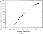
На фиг.2 показана зависимость выходной мощности излучения первой стоксовой компоненты от входной мощности излучения накачки.Figure 2 shows the dependence of the output radiation power of the first Stokes component on the input radiation power of the pump.
На фиг.3 приведен спектр выходного излучения ВКР-лазера, генерирующего излучение первой и второй стоксовых компонент.Figure 3 shows the spectrum of the output radiation of a Raman laser, generating radiation of the first and second Stokes components.
Заявляемое устройство (см. фиг.1) содержит источник излучения накачки, например лазер 1, фокусирующую систему 2 и ВКР-активную среду 3, помещенную между входным 4 и выходным 5 зеркалами резонатора. Лазер 1 накачки может представлять собой как источник непрерывного одночастотного излучения, так и источник непрерывного многочастотного излучения, например аргоновый лазер. Зеркало 4 имеет максимальное пропускание на длине волны излучения накачки и максимальное отражение на длине волны излучения первой стоксовой компоненты. В случае необходимости генерации других компонент рассеяния зеркало 4 обладает также максимальным отражением на соответствующих длинах волн. Для случая генерации излучения первой стоксовой компоненты зеркало 5 имеет оптимальное отражение на этой длине волны. При генерации других компонент оно имеет оптимальное отражение на длине волны генерируемой компоненты и максимальное отражение для компонент более низкого порядка. ВКР-активная среда является сплошной, оптически однородной и может представлять собой, например, кристалл нитрата бария, KGd(WO4)2, BaWO4, KY(WO4)2, KYb(WO4)2, VYO4. ВКР-активная среда может также представлять собой полупроводниковый кристалл, например, кристалл кремния. ВКР-активная среда может представлять собой также газ (например, водород) или жидкость (например, нитробензол), помещенный в соответствующую кювету. В силу описанных выше особенностей непрерывного ВКР-лазера тип среды не оказывает существенного влияния на работу устройства и результат.The inventive device (see figure 1) contains a pump radiation source, for example a laser 1, a focusing system 2 and a Raman-active medium 3, placed between the input 4 and output 5 mirrors of the resonator. The pump laser 1 can be either a single-frequency continuous radiation source or a continuous multi-frequency radiation source, for example, an argon laser. Mirror 4 has a maximum transmittance at the pump radiation wavelength and a maximum reflection at the radiation wavelength of the first Stokes component. If it is necessary to generate other scattering components, mirror 4 also has a maximum reflection at the corresponding wavelengths. For the case of the generation of radiation of the first Stokes component, mirror 5 has an optimal reflection at this wavelength. When generating other components, it has an optimal reflection at the wavelength of the generated component and maximum reflection for components of a lower order. The SRS-active medium is continuous, optically homogeneous and can be, for example, a barium nitrate crystal, KGd (WO 4 ) 2 , BaWO 4 , KY (WO 4 ) 2 , KYb (WO 4 ) 2 , VYO 4 . The SRS-active medium may also be a semiconductor crystal, for example, a silicon crystal. The SRS-active medium can also be a gas (for example, hydrogen) or a liquid (for example, nitrobenzene), placed in an appropriate cuvette. Due to the above-described features of a cw Raman laser, the type of medium does not significantly affect the operation of the device and the result.
Устройство работает следующим образом: излучение накачки с помощью фокусирующей системы 2 фокусируется в комбинационно-активную среду 3, проходя через зеркало 4. Это излучение начинает спонтанно рассеиваться в комбинационно-активной среде, создавая затравочное излучение для ВКР-генерации. Сама ВКР-генерация возникает в случае, если усиление на частоте генерируемой стоксовой компоненты, обеспечиваемое накачкой, будет превышать потери, включающие потери на просветленных внутрирезонаторных поверхностях, потери на нерезонансном поглощении в рассеивающей среде, "полезные" потери на зеркалах и т.д. Поэтому одним из путей создания условий с превышением усиления над потерями является уменьшение потерь, в том числе и полезных, т.е. выбор зеркал 4 и 5 с максимально высоким коэффициентом отражения на длине волны первой стоксовой компоненты. Если это условие выполнено, то начинается рост мощности стоксовой компоненты и развивается ВКР-генерация. Рост будет происходить до тех пор, пока по каким-нибудь причинам усиление не сравняется с потерями. Это выравнивание может происходить как за счет роста потерь, так и за счет падения усиления вследствие истощения накачки.The device operates as follows: the pump radiation using a focusing system 2 is focused into the Raman-active medium 3, passing through the mirror 4. This radiation begins to spontaneously scatter in the Raman-active medium, creating a seed radiation for Raman generation. Raman generation itself occurs if the gain at the frequency of the generated Stokes component provided by the pump exceeds the losses, including losses on the bleached intracavity surfaces, losses on non-resonant absorption in the scattering medium, “useful” losses on the mirrors, etc. Therefore, one of the ways to create conditions with excess gain over losses is to reduce losses, including useful ones, i.e. the choice of mirrors 4 and 5 with the highest possible reflection coefficient at the wavelength of the first Stokes component. If this condition is met, then the power of the Stokes component begins to increase and Raman generation develops. Growth will occur until, for some reason, the gain equals the loss. This alignment can occur both due to an increase in losses, and due to a decrease in gain due to depletion of the pump.
Рост потерь может обеспечиваться, например, появлением второй стоксовой компоненты. Если мощность излучения первой стоксовой компоненты достигнет определенного предела, при котором выполняются пороговые условия генерации второй стоксовой компоненты, то начнется развитие второй стоксовой компоненты и рост первой при этом прекратится. Этого ограничения можно избежать, создав условия, неблагоприятные для генерации второй стоксовой компоненты.The increase in losses can be provided, for example, by the appearance of a second Stokes component. If the radiation power of the first Stokes component reaches a certain limit at which the threshold conditions for the generation of the second Stokes component are satisfied, then the development of the second Stokes component will begin and the growth of the first will stop. This limitation can be avoided by creating conditions unfavorable for the generation of the second Stokes component.
В то же время генерация второй, а также высших стоксовых и антистоксовых компонент может быть использована как полезный эффект, позволяющий генерировать излучение в новых диапазонах со смещением частоты излучения накачки на величину нескольких комбинационных сдвигов как в сторону длинноволновой области (стоксово смещение), так и в сторону коротковолновой области спектра (антистоксово смещение). Для этого необходимо создание достаточной добротности резонатора не только на длине волны излучения первой стоксовой компоненты, но также и на длинах волн генерации нужных компонент рассеяния. Причем для генерации, например, третьей стоксовой компоненты необходимо обеспечить генерацию компонент более низкого порядка, т.е. второй и первой стоксовых компонент.At the same time, the generation of the second, as well as higher Stokes and anti-Stokes components can be used as a useful effect, which allows generating radiation in new ranges with a shift in the pump radiation frequency by several Raman shifts both toward the long-wavelength region (Stokes shift) and side of the short-wavelength region of the spectrum (anti-Stokes shift). For this, it is necessary to create a sufficient Q-factor of the resonator not only at the radiation wavelength of the first Stokes component, but also at the generation wavelengths of the necessary scattering components. Moreover, for the generation, for example, of the third Stokes component, it is necessary to ensure the generation of lower-order components, i.e. second and first Stokes components.
Поскольку в процессе комбинационного рассеяния часть энергии фотонов накачки передается рассеивающей среде, это приводит к ее нагреванию. Если в импульсном режиме этот эффект может и не приводить к существенным последствиям, то в непрерывном режиме количество теплоты, накапливаемой в среде, может стать настолько существенным, что приведет, в частности, к образованию сильной термической линзы в резонаторе ВКР-лазера. Для минимизации влияния тепловых эффектов может быть использован специальный теплоотвод (на чертежах не показан), в который помещается комбинационно-активная среда. Особенно эффективным такой подход может быть в случае использования твердотельных комбинационно-активных сред, обладающих повышенной теплопроводностью по сравнению с газами.Since in the process of Raman scattering, part of the energy of the pump photons is transferred to the scattering medium, this leads to its heating. If in the pulsed mode this effect may not lead to significant consequences, then in the continuous mode the amount of heat accumulated in the medium can become so significant that, in particular, it will lead to the formation of a strong thermal lens in the Raman laser cavity. To minimize the influence of thermal effects, a special heat sink (not shown in the drawings) can be used, in which the Raman-active medium is placed. Such an approach can be especially effective in the case of using solid-state Raman-active media with increased thermal conductivity compared to gases.
Заявляемое устройство иллюстрируют следующие конкретные неограничивающие примеры.The inventive device is illustrated by the following specific non-limiting examples.
Пример 1. ВКР-лазер, генерирующий излучение только на частоте первой стоксовой компоненты (длина волны 543 нм)Example 1. A Raman laser generating radiation only at the frequency of the first Stokes component (wavelength 543 nm)
В качестве сплошной, оптически однородной комбинационно-активной среды использован кристалл нитрата бария длиной 68 мм. Торцы кристалла были просветлены и имели минимальное отражение в диапазоне 490-580 нм. Кристалл помещен в резонатор, близкий к концентрическому. В качестве источника возбуждения использован аргоновый лазер фирмы Spectra-Physics модель 2085, обеспечивавший в многочастотном режиме до 15 Вт выходного излучения с шириной спектра около 0.2 см-1 на длине волны 514.5 нм. Возбуждающее излучение фокусировали в комбинационно-активный кристалл линзой с фокусным расстоянием 15 см. Использовали входное зеркало с радиусом кривизны 7.5 см, пропусканием на длине волны 514 нм 79%, отражением на длине волны 543 нм 99.84% и 99.98% на длине волны 577 нм, выходное зеркало с радиусом кривизны 8 см, и отражением 99.93% на длине волны 514 нм, 99.64% на длине волны 543 нм и 28% на длине волны 577 нм. Длина резонатора составляла 17.6 см. Зависимость мощности выходного излучения первой стоксовой компоненты (543 нм) от мощности накачки приведена на фиг.2. Порог генерации составил 2 Вт при расчетном значении 1.7 Вт, в предположении, что эффективная длина Leff=5.07 см, показатель преломления кристалла нитрата бария n=1.58, эффективное значение площади поперечного сечения пучка накачки Seff=0.018 мм2, М2 - фактор пучка накачки =1.7.A 68 mm long barium nitrate crystal was used as a continuous, optically homogeneous Raman-active medium. The ends of the crystal were enlightened and had a minimal reflection in the range of 490-580 nm. The crystal is placed in a resonator close to concentric. Spectra-Physics Model 2085 argon argon laser was used as an excitation source, providing in the multi-frequency mode up to 15 W of output radiation with a spectral width of about 0.2 cm -1 at a wavelength of 514.5 nm. The exciting radiation was focused into a Raman-active crystal with a lens with a focal length of 15 cm. An input mirror was used with a radius of curvature of 7.5 cm, transmittance at a wavelength of 514 nm, 79%, reflection at a wavelength of 543 nm, 99.84% and 99.98% at a wavelength of 577 nm, an output mirror with a radius of curvature of 8 cm and a reflection of 99.93% at a wavelength of 514 nm, 99.64% at a wavelength of 543 nm and 28% at a wavelength of 577 nm. The cavity length was 17.6 cm. The dependence of the output radiation power of the first Stokes component (543 nm) on the pump power is shown in Fig. 2. The generation threshold was 2 W with a calculated value of 1.7 W, under the assumption that the effective length L eff = 5.07 cm, the refractive index of the barium nitrate crystal n = 1.58, the effective value of the cross section of the pump beam S eff = 0.018 mm 2 , M 2 is the factor pump beam = 1.7.
Пример 2. Во втором случае был реализован ВКР-лазер, генерирующий излучение на длинах волн первой и второй стоксовых компонент (543 нм и 577 нм).Example 2. In the second case, a Raman laser was implemented that generated radiation at the wavelengths of the first and second Stokes components (543 nm and 577 nm).
В качестве сплошной, оптически однородной комбинационно-активной среды использован кристалл нитрата бария длиной 68 мм. Торцы кристалла были просветлены и имели минимальное отражение в диапазоне 490-580 нм. Кристалл помещен в резонатор, близкий к концентрическому. В качестве источника возбуждения использован аргоновый лазер фирмы Spectra-Physics модель 2085, обеспечивавший в многочастотном режиме до 15 Вт выходного излучения с шириной спектра около 0.2 см-1 на длине волны 514.5 нм. Возбуждающее излучение фокусировали в комбинационно-активный кристалл линзой с фокусным расстоянием 15 см. В качестве выходного зеркала использовали зеркало с радиусом кривизны 7.5 см и отражающее 38% на длине волны 514 нм, 99.87% на длине волны 543 нм и 99.97% на длине волны 577 нм. Длина резонатора составляла 17.2 см. При мощности возбуждения 6.45 Вт получено 24 мВт на длине волны первой стоксовой компоненты и около 150 мкВт на длине волны второй стоксовой компоненты. Спектр выходного излучения в этом случае представлен на фиг.3.A 68 mm long barium nitrate crystal was used as a continuous, optically homogeneous Raman-active medium. The ends of the crystal were enlightened and had a minimal reflection in the range of 490-580 nm. The crystal is placed in a resonator close to concentric. Spectra-Physics Model 2085 argon argon laser was used as an excitation source, providing in the multi-frequency mode up to 15 W of output radiation with a spectral width of about 0.2 cm -1 at a wavelength of 514.5 nm. The exciting radiation was focused into a Raman-active crystal with a lens with a focal length of 15 cm. A mirror with a radius of curvature of 7.5 cm and reflecting 38% at a wavelength of 514 nm, 99.87% at a wavelength of 543 nm, and 99.97% at a wavelength of 577 was used as an output mirror. nm The cavity length was 17.2 cm. With an excitation power of 6.45 W, 24 mW were obtained at the wavelength of the first Stokes component and about 150 μW at the wavelength of the second Stokes component. The spectrum of the output radiation in this case is presented in Fig.3.
Таким образом, настоящее изобретение позволяет реализовать компактный непрерывный нерезонансный ВКР-лазер. В этой конструкции может быть использован сплошной, оптически однородный комбинационно-активный элемент в виде кристалла. кюветы с жидкостью или газом. Особенно привлекательна возможность использования для возбуждения непрерывных лазеров, работающих как в одночастотном, так и в многочастотном режимах, с выходной мощностью до 10 Вт.Thus, the present invention makes it possible to realize a compact cw nonresonant Raman laser. In this design, a solid, optically uniform Raman-active element in the form of a crystal can be used. cuvettes with liquid or gas. Particularly attractive is the possibility of using continuous-wave lasers operating in both single-frequency and multi-frequency modes with an output power of up to 10 watts for excitation.
Следует отметить, что эффект ВКР позволяет получать лазерное излучение в средах без инверсии, что может быть использовано для создания лазерных источников, в том числе и непрерывных, на относительно дешевых средах с хорошо изученными свойствами, для которых развиты технологии производства.It should be noted that the SRS effect allows one to obtain laser radiation in media without inversion, which can be used to create laser sources, including cw, on relatively cheap media with well-studied properties, for which production technologies are developed.
Источники информации:Information sources:
1. R.Max, U.Huber, I.Abdul-Halim, J.Heppner, Y.Ni, G.Willenberg, and C.O.Weiss, IEEE J. Quantum Electron. QE-17, 1123 (1981).1. R. Max, U. Huber, I. Abdul-Halim, J. Heppner, Y. Ni, G. Willenberg, and C. O. Weiss, IEEE J. Quantum Electron. QE-17, 1123 (1981).
2. M.Poelker and P.Kumar, Opt. Lett. 17, 399 (1992).2. M. Poelker and P. Kumar, Opt. Lett. 17, 399 (1992).
3. G.Grynberg, E.Giacobino, and F.Biraben, Opt. Commun. 36, 403 (1981).3. G. Grynberg, E. Giacobino, and F. Biraben, Opt. Commun. 36, 403 (1981).
4. S.N.Jabr, Opt. Lett. 12, 690 (1987).4. S.N. Jabr, Opt. Lett. 12, 690 (1987).
5. Патент США №6,151,337, H 01 S 3/30, публ. 21.11.2000.5. US patent No. 6,151,337, H 01 S 3/30, publ. 11/21/2000.
6. Патент Канады №1,115,395, H 03 S 3/07, 3/08, публ. 29.12.1981 (прототип).6. Canadian patent No. 1,115,395, H 03 S 3/07, 3/08, publ. 12/29/1981 (prototype).
7. Годовой отчет №2 по проекту МНТЦ В-266-99 "Полностью твердотельные компактные узкополосные миллиджоулевого уровня энергии источники лазерного излучения для диапазона 187-1700 нм".7. Annual report No. 2 on the ISTC project V-266-99 "Fully solid-state compact narrow-band millijoule-level energy sources of laser radiation for the range 187-1700 nm."
8. W.Koechner, Solid-State Laser Engineering, Second Edition, Springer-Verlag. 1988 599.8. W. Koechner, Solid-State Laser Engineering, Second Edition, Springer-Verlag. 1988 599.
9. А.З.Грасюк. Труды ФИАН СССР, т.76, 1974, 75-116.9. A.Z. Grazyuk. Proceedings of the Lebedev Physical Institute of the USSR, vol. 76, 1974, 75-116.
Claims (19)
Priority Applications (1)
| Application Number | Priority Date | Filing Date | Title |
|---|---|---|---|
| RU2005110806/28A RU2292103C1 (en) | 2005-04-13 | 2005-04-13 | Continuous stimulated-scattering combination laser |
Applications Claiming Priority (1)
| Application Number | Priority Date | Filing Date | Title |
|---|---|---|---|
| RU2005110806/28A RU2292103C1 (en) | 2005-04-13 | 2005-04-13 | Continuous stimulated-scattering combination laser |
Publications (2)
| Publication Number | Publication Date |
|---|---|
| RU2005110806A RU2005110806A (en) | 2006-10-20 |
| RU2292103C1 true RU2292103C1 (en) | 2007-01-20 |
Family
ID=37437646
Family Applications (1)
| Application Number | Title | Priority Date | Filing Date |
|---|---|---|---|
| RU2005110806/28A RU2292103C1 (en) | 2005-04-13 | 2005-04-13 | Continuous stimulated-scattering combination laser |
Country Status (1)
| Country | Link |
|---|---|
| RU (1) | RU2292103C1 (en) |
Citations (5)
| Publication number | Priority date | Publication date | Assignee | Title |
|---|---|---|---|---|
| GB1210597A (en) * | 1967-04-21 | 1970-10-28 | Ibm | Laser device |
| SU368690A1 (en) * | 1970-07-30 | 1973-01-26 | Ф. А. Королев, В. И. Одинцов , Е. Ю. Соколова Московский государственный университет М. В. Ломоносова | GENERATOR OF RADIATION OF A FORCED COMBINATION SCATTERING |
| SU346999A1 (en) * | 1970-11-30 | 1977-08-25 | Институт Физики Ан Украинской Сср | Laser |
| RU2012119C1 (en) * | 1991-08-14 | 1994-04-30 | Научно-исследовательский институт прикладной физики при Иркутском государственном университете | Laser based on stimulated combination scattering (scs) |
| US6151337A (en) * | 1998-05-06 | 2000-11-21 | The Research And Development Institute, Inc. | Continuous-wave Raman laser having a high-finesse cavity |
-
2005
- 2005-04-13 RU RU2005110806/28A patent/RU2292103C1/en not_active IP Right Cessation
Patent Citations (5)
| Publication number | Priority date | Publication date | Assignee | Title |
|---|---|---|---|---|
| GB1210597A (en) * | 1967-04-21 | 1970-10-28 | Ibm | Laser device |
| SU368690A1 (en) * | 1970-07-30 | 1973-01-26 | Ф. А. Королев, В. И. Одинцов , Е. Ю. Соколова Московский государственный университет М. В. Ломоносова | GENERATOR OF RADIATION OF A FORCED COMBINATION SCATTERING |
| SU346999A1 (en) * | 1970-11-30 | 1977-08-25 | Институт Физики Ан Украинской Сср | Laser |
| RU2012119C1 (en) * | 1991-08-14 | 1994-04-30 | Научно-исследовательский институт прикладной физики при Иркутском государственном университете | Laser based on stimulated combination scattering (scs) |
| US6151337A (en) * | 1998-05-06 | 2000-11-21 | The Research And Development Institute, Inc. | Continuous-wave Raman laser having a high-finesse cavity |
Also Published As
| Publication number | Publication date |
|---|---|
| RU2005110806A (en) | 2006-10-20 |
Similar Documents
| Publication | Publication Date | Title |
|---|---|---|
| Elder et al. | Diode-pumped, room-temperature Tm: YAP laser | |
| Li et al. | Simultaneous dual-wavelength continuous wave laser operation at 1.06 μm and 946 nm in Nd: YAG and their frequency doubling | |
| US20060146901A1 (en) | Holmium doped 2.1 micron crystal laser | |
| Shamrakov et al. | Superradiant film laser operation in red perylimide dye doped silica—polymethylmethacrylate composite | |
| CN113363798B (en) | Adjustable high-optical-efficiency broadband multi-longitudinal-mode Raman microchip laser | |
| CN105846302A (en) | Novel Kerr-lens mode-locking Cr: ZnS femtosecond laser | |
| CN110265863A (en) | A kind of intracavity anti-Stokes Raman laser and stimulated Raman blue shift wavelength maximization output method | |
| Wang et al. | Sub-nanosecond, high peak power Yb: YAG/Cr4+: YAG/YVO4 passively Q-switched Raman micro-laser operating at 1134 nm | |
| Li et al. | Blue-pumped single-longitudinal-mode deep red band Pr: YLF Laser | |
| Xue et al. | Diode-pumped continuous-wave Pr: YLF cyan laser | |
| Dong et al. | Continuous-wave and Q-switched microchip laser performance of Yb: Y3Sc2Al3O12 crystals | |
| US7116687B2 (en) | High repetition rate passively Q-switched laser for blue laser based on interactions in fiber | |
| Mateos et al. | Ho: KY (WO4) 2 thin-disk laser passively Q-switched by a GaSb-based SESAM | |
| Wang et al. | Multiwavelength, sub-nanosecond Yb: YAG/Cr4+: YAG/YVO4 passively Q-switched Raman microchip laser | |
| US6137813A (en) | Yb-doped fiber laser operating near EDFA absorption band | |
| Młyńczak et al. | Generation investigation of" eye-safe" microchip lasers pumped by 974 nm and 939 nm wavelength. | |
| RU2292103C1 (en) | Continuous stimulated-scattering combination laser | |
| McKinnie et al. | Ti/sup 3+/ion concentration and Ti: sapphire laser performance | |
| Lei et al. | High-power CW 1048 nm Yb: YAG dual-ended diode-pumped zigzag slab laser | |
| CN111180985B (en) | An experimental device and method for generating high repetition rate femtosecond laser | |
| CN117559205A (en) | A method to suppress high-order Raman based on low phonon energy fiber | |
| Říha et al. | Laser-diode-pumped Cr: ZnSe CW laser tunable in mid-IR range of 2.05-2.65 μm | |
| CN114336252A (en) | A narrow linewidth solid-state laser | |
| RU2300834C2 (en) | Compact continuous solid-state fcd laser (alternatives) | |
| Dashkevich et al. | Comparative studies of eye-safe intracavity and extracavity optical parametric oscillators with an unstable telescopic cavity |
Legal Events
| Date | Code | Title | Description |
|---|---|---|---|
| MM4A | The patent is invalid due to non-payment of fees |
Effective date: 20120414 |