RU2292037C2 - Method of recording goniometric characteristics of paint-and-varnish film - Google Patents
Method of recording goniometric characteristics of paint-and-varnish film Download PDFInfo
- Publication number
- RU2292037C2 RU2292037C2 RU2003132476/28A RU2003132476A RU2292037C2 RU 2292037 C2 RU2292037 C2 RU 2292037C2 RU 2003132476/28 A RU2003132476/28 A RU 2003132476/28A RU 2003132476 A RU2003132476 A RU 2003132476A RU 2292037 C2 RU2292037 C2 RU 2292037C2
- Authority
- RU
- Russia
- Prior art keywords
- sample
- light source
- light
- image
- image forming
- Prior art date
Links
- 238000000034 method Methods 0.000 title claims abstract description 16
- 239000002966 varnish Substances 0.000 title 1
- 230000003595 spectral effect Effects 0.000 claims description 9
- 239000003973 paint Substances 0.000 claims description 7
- 238000005286 illumination Methods 0.000 abstract description 10
- 230000003993 interaction Effects 0.000 abstract description 4
- 230000005540 biological transmission Effects 0.000 abstract description 2
- 239000000463 material Substances 0.000 abstract description 2
- 239000000126 substance Substances 0.000 abstract 1
- 239000000523 sample Substances 0.000 description 50
- 238000000576 coating method Methods 0.000 description 16
- 230000003287 optical effect Effects 0.000 description 16
- 239000000975 dye Substances 0.000 description 11
- 239000011248 coating agent Substances 0.000 description 9
- 239000002245 particle Substances 0.000 description 8
- 238000005259 measurement Methods 0.000 description 7
- 230000000007 visual effect Effects 0.000 description 6
- 239000003086 colorant Substances 0.000 description 5
- 238000003384 imaging method Methods 0.000 description 5
- 239000011152 fibreglass Substances 0.000 description 4
- 238000012417 linear regression Methods 0.000 description 4
- 206010034972 Photosensitivity reaction Diseases 0.000 description 2
- 238000010586 diagram Methods 0.000 description 2
- 238000005516 engineering process Methods 0.000 description 2
- 230000036211 photosensitivity Effects 0.000 description 2
- 230000036962 time dependent Effects 0.000 description 2
- RYYVLZVUVIJVGH-UHFFFAOYSA-N caffeine Chemical compound CN1C(=O)N(C)C(=O)C2=C1N=CN2C RYYVLZVUVIJVGH-UHFFFAOYSA-N 0.000 description 1
- 238000004364 calculation method Methods 0.000 description 1
- 238000012512 characterization method Methods 0.000 description 1
- 238000006243 chemical reaction Methods 0.000 description 1
- 239000008199 coating composition Substances 0.000 description 1
- 239000011247 coating layer Substances 0.000 description 1
- 238000004590 computer program Methods 0.000 description 1
- 238000012937 correction Methods 0.000 description 1
- 230000003247 decreasing effect Effects 0.000 description 1
- 239000003365 glass fiber Substances 0.000 description 1
- 239000010410 layer Substances 0.000 description 1
- 239000002932 luster Substances 0.000 description 1
- 238000013178 mathematical model Methods 0.000 description 1
- 229910052751 metal Inorganic materials 0.000 description 1
- 239000002184 metal Substances 0.000 description 1
- 238000012545 processing Methods 0.000 description 1
- 239000013074 reference sample Substances 0.000 description 1
- 230000035945 sensitivity Effects 0.000 description 1
- 238000012360 testing method Methods 0.000 description 1
- 229910052721 tungsten Inorganic materials 0.000 description 1
- 239000010937 tungsten Substances 0.000 description 1
- -1 tungsten halide Chemical class 0.000 description 1
- 229910052724 xenon Inorganic materials 0.000 description 1
- FHNFHKCVQCLJFQ-UHFFFAOYSA-N xenon atom Chemical compound [Xe] FHNFHKCVQCLJFQ-UHFFFAOYSA-N 0.000 description 1
Images

Classifications
-
- G—PHYSICS
- G01—MEASURING; TESTING
- G01J—MEASUREMENT OF INTENSITY, VELOCITY, SPECTRAL CONTENT, POLARISATION, PHASE OR PULSE CHARACTERISTICS OF INFRARED, VISIBLE OR ULTRAVIOLET LIGHT; COLORIMETRY; RADIATION PYROMETRY
- G01J3/00—Spectrometry; Spectrophotometry; Monochromators; Measuring colours
- G01J3/02—Details
- G01J3/0205—Optical elements not provided otherwise, e.g. optical manifolds, diffusers, windows
- G01J3/0216—Optical elements not provided otherwise, e.g. optical manifolds, diffusers, windows using light concentrators or collectors or condensers
-
- G—PHYSICS
- G01—MEASURING; TESTING
- G01J—MEASUREMENT OF INTENSITY, VELOCITY, SPECTRAL CONTENT, POLARISATION, PHASE OR PULSE CHARACTERISTICS OF INFRARED, VISIBLE OR ULTRAVIOLET LIGHT; COLORIMETRY; RADIATION PYROMETRY
- G01J3/00—Spectrometry; Spectrophotometry; Monochromators; Measuring colours
- G01J3/02—Details
- G01J3/10—Arrangements of light sources specially adapted for spectrometry or colorimetry
-
- G—PHYSICS
- G01—MEASURING; TESTING
- G01J—MEASUREMENT OF INTENSITY, VELOCITY, SPECTRAL CONTENT, POLARISATION, PHASE OR PULSE CHARACTERISTICS OF INFRARED, VISIBLE OR ULTRAVIOLET LIGHT; COLORIMETRY; RADIATION PYROMETRY
- G01J3/00—Spectrometry; Spectrophotometry; Monochromators; Measuring colours
- G01J3/46—Measurement of colour; Colour measuring devices, e.g. colorimeters
- G01J3/50—Measurement of colour; Colour measuring devices, e.g. colorimeters using electric radiation detectors
- G01J3/504—Goniometric colour measurements, for example measurements of metallic or flake based paints
-
- G—PHYSICS
- G01—MEASURING; TESTING
- G01J—MEASUREMENT OF INTENSITY, VELOCITY, SPECTRAL CONTENT, POLARISATION, PHASE OR PULSE CHARACTERISTICS OF INFRARED, VISIBLE OR ULTRAVIOLET LIGHT; COLORIMETRY; RADIATION PYROMETRY
- G01J3/00—Spectrometry; Spectrophotometry; Monochromators; Measuring colours
- G01J3/46—Measurement of colour; Colour measuring devices, e.g. colorimeters
- G01J3/52—Measurement of colour; Colour measuring devices, e.g. colorimeters using colour charts
- G01J3/524—Calibration of colorimeters
-
- G—PHYSICS
- G01—MEASURING; TESTING
- G01N—INVESTIGATING OR ANALYSING MATERIALS BY DETERMINING THEIR CHEMICAL OR PHYSICAL PROPERTIES
- G01N21/00—Investigating or analysing materials by the use of optical means, i.e. using sub-millimetre waves, infrared, visible or ultraviolet light
- G01N21/17—Systems in which incident light is modified in accordance with the properties of the material investigated
- G01N21/55—Specular reflectivity
- G01N21/57—Measuring gloss
Abstract
Description
Изобретение относится к способу и устройству для регистрации визуальных свойств поверхности, например цвета, блеска, текстуры и т.д., окрашенных покровных пленок с использованием устройства формирования изображения, источника света и области образцов для размещения образца, поверхность которого подлежит исследованию. Визуальные признаки поверхности могут зависеть от оптической геометрии, которая определяется размещением наблюдаемого объекта относительно наблюдателя и источника света. Эта зависимость может иметь место, например, в пленках покрытий, содержащих эффектные красители. Зависимость визуальных свойств от оптической геометрии обычно называется гониохроматизмом или «флоп-поведением». В оптической геометрии направлением наблюдения является линия между наблюдателем и наблюдаемой точкой наблюдаемого объекта, и направлением освещения является линия между источником света и наблюдаемой точкой. Направлением отражения является линия, полученная зеркальным отражением направления освещения относительно плоскости, перпендикулярной к поверхности образца. Флоп-угол, также именуемый аспекулярным углом, это угол между направлением наблюдения и направлением отражения. Кроме того, блеск эффектных или безэффекных пленок зависит от оптической геометрии.The invention relates to a method and apparatus for registering visual properties of a surface, for example color, gloss, texture, etc., of colored coating films using an image forming apparatus, a light source, and a sample region for arranging a sample whose surface is to be examined. Visual signs of the surface may depend on the optical geometry, which is determined by the location of the observed object relative to the observer and the light source. This dependence can occur, for example, in coating films containing spectacular dyes. The dependence of visual properties on optical geometry is usually called goniochromatism or “flop behavior”. In optical geometry, the direction of observation is the line between the observer and the observed point of the observed object, and the direction of illumination is the line between the light source and the observed point. The direction of reflection is the line obtained by specular reflection of the direction of illumination relative to a plane perpendicular to the surface of the sample. The flop angle, also referred to as the aspect angle, is the angle between the direction of observation and the direction of reflection. In addition, the luster of spectacular or effectless films depends on the optical geometry.
Эффектные красители используются в покрытиях для получения оптических эффектов, например, металлического или перламутрового вида. Обычно в пленке покрытия, содержащей металлические красители, яркость зависит от оптической геометрии, тогда как в покрытиях, содержащих перламутровые красители, оттенок изменяется с оптической геометрией. Это усложняет определение характеристик визуальных характеристик таких покровных пленок. Дополнительным усложнением в этой связи является появление пятен с локальным сильным рассеянием при наблюдении покровной пленки на малом расстоянии, вследствие наличия хлопьев красителя. Тогда как чистый цвет можно характеризовать спектральным распределением значений отражательной способности, покрытия, содержащие эффектные красители, требуют учета угловой и пространственной зависимости.Spectacular dyes are used in coatings to produce optical effects, for example, metallic or pearlescent. Typically, in a coating film containing metallic dyes, the brightness depends on the optical geometry, while in coatings containing pearlescent dyes, the tint changes with optical geometry. This complicates the characterization of the visual characteristics of such coating films. An additional complication in this regard is the appearance of spots with local strong scattering when observing the coating film at a short distance, due to the presence of dye flakes. While pure color can be characterized by the spectral distribution of reflectance values, coatings containing spectacular dyes require taking into account the angular and spatial dependences.
До сих пор, зависимость яркости и цвета металлических и перламутровых покрытий от оптической геометрии исследовали с использованием спектрофотометра для ограниченного количества различных геометрических конфигураций измерения. Однако это приводит к неполной картине, обеспечивающей данные лишь для весьма ограниченного количества оптических геометрических конфигураций.Until now, the dependence of the brightness and color of metallic and pearlescent coatings on optical geometry has been investigated using a spectrophotometer for a limited number of different geometric measurement configurations. However, this leads to an incomplete picture providing data only for a very limited number of optical geometric configurations.
В патенте США 5550632 раскрыты способ и устройство для оценки лакокрасочных пленок с использованием цифрового фотоаппарата. Единомоментно регистрируется только одна оптическая геометрия, и, поскольку фотоаппарат сфокусирован, только один флоп-угол. Поскольку характеристики покровного слоя, содержащего эффектные красители, зависят от флоп-угла, этот способ нельзя использовать для оценки таких эффектных покрытий в одном цикле регистрации.US Pat. No. 5,550,632 discloses a method and apparatus for evaluating paint films using a digital camera. Only one optical geometry is recorded at a time, and since the camera is focused, only one flop angle. Since the characteristics of the coating layer containing effective dyes depend on the flop angle, this method cannot be used to evaluate such effective coatings in a single recording cycle.
Задачей изобретения является система, позволяющая осуществлять оценку поверхности при одном цикле регистрации по непрерывному диапазону флоп-углов.The objective of the invention is a system that allows you to evaluate the surface with a single registration cycle over a continuous range of flop angles.
Для решения задачи изобретения предусмотрено устройство для регистрации характеристик поверхности, зависящих от флоп-угла, содержащее устройство формирования изображения для регистрации взаимодействия света с поверхностью, источник света и область образцов для размещения образца, поверхность которого подлежит исследованию, отличающееся тем, что диапазон охвата устройства формирования изображения охватывает непрерывный диапазон направлений наблюдения и тем, что устройство формирования изображения, источник света и область образцов размещены таким образом, что в одном изображении, по меньшей мере, одна из характеристик поверхности регистрируется как функция флоп-угла. Регистрацию можно использовать для визуальной оценки и сравнения или, в зависимости от способности устройства формирования изображения измерять регистрируемые сигналы, для измерения или обработки данных. Частными примерами использования являются измерение блеска и цветовое согласование.To solve the problem of the invention, there is provided a device for recording surface characteristics depending on the flop angle, comprising an image forming device for detecting the interaction of light with the surface, a light source and a sample area for receiving a sample, the surface of which is to be studied, characterized in that the coverage range of the forming device image covers a continuous range of directions of observation and the fact that the imaging device, the light source and the region of the sample It is arranged in such a way that in one image at least one of the characteristics of the surface is recorded as a function of the flop angle. Registration can be used for visual assessment and comparison, or, depending on the ability of the imaging device to measure the recorded signals, for measuring or processing data. Particular examples of use are gloss measurement and color matching.
Устройство или система, согласно настоящему изобретению, в частности, предназначено для оценки флоп-поведения или гониохроматизма поверхности, с покрытием, содержащим эффектные красители.The device or system according to the present invention, in particular, is designed to assess the flop behavior or goniochromatism of the surface, with a coating containing effective dyes.
Для получения полезной картины флоп-поведения, диапазон флоп-углов, определенных выше, должен, предпочтительно, охватывать более 40 градусов, более предпочтительно, более 50 градусов.In order to obtain a useful picture of flop behavior, the range of flop angles defined above should preferably span more than 40 degrees, more preferably more than 50 degrees.
Для некоторых типов поверхности, например покровных пленок, содержащих металлические красители, цвет является более темным при больших флоп-углах. Для использования в таком случае полного диапазона измерений распределение света, предпочтительно, изменяется в диапазоне обзора устройства формирования изображения, предпочтительно, в соответствии с возрастающей или убывающей функцией. Эта функция зависит от типа материала. Распределение света может изменяться за счет изменения выхода света источника света, как функции угла освещения. Альтернативно, распределение света может изменяться за счет использования соответствующих фильтров.For some types of surfaces, such as coating films containing metallic dyes, the color is darker at large flop angles. For use in this case, the full range of measurements, the light distribution preferably varies in the viewing range of the image forming apparatus, preferably in accordance with an increasing or decreasing function. This function depends on the type of material. The distribution of light may vary by changing the light output of the light source as a function of the angle of illumination. Alternatively, the light distribution may be varied by using appropriate filters.
В предпочтительной конфигурации, источник света может быть линейным источником, например полосковым источником света TL, горизонтальной щелью в рассеивателе света, массивом точечных источников, например СИД или стеклянных волокон и т.д. Альтернативно источник света может быть точечным источником.In a preferred configuration, the light source may be a linear source, for example a TL strip light source, a horizontal slit in the light diffuser, an array of point sources, such as LEDs or glass fibers, etc. Alternatively, the light source may be a point source.
Подходящим устройством формирования изображения в конфигурации, отвечающей изобретению, является камера на ПЗС (приборах с зарядовой связью). Подходящими фотоаппаратами на ПЗС являются, например, Ricoh® RDS 5000, Olympus® C-2000Z, Minolta® Dimage® RD 3000 и Nikon® Coolpix® 950.A suitable imaging device in a configuration consistent with the invention is a CCD camera (charge coupled devices). Suitable CCD cameras are, for example, Ricoh ® RDS 5000, Olympus ® C-2000Z, Minolta ® Dimage ® RD 3000 and Nikon ® Coolpix ® 950.
Другую группу устройств, предназначенных для использования в настоящем изобретении, образуют цифровые видеокамеры. Благодаря использованию видеокамеры, флоп-угол может изменяться не только как функция положения, но, альтернативно или дополнительно, как функция времени. Использование видеокамеры также позволяет отслеживать зависящие от времени изменения визуальных характеристик исследуемой поверхности в течение периода времени, например внешний вид покровной пленки в ходе отверждения.Another group of devices for use in the present invention is constituted by digital video cameras. Thanks to the use of a video camera, the flop angle can change not only as a function of position, but, alternatively or additionally, as a function of time. Using a video camera also allows you to track time-dependent changes in the visual characteristics of the test surface over a period of time, for example, the appearance of the coating film during curing.
При использовании цифровой камеры каждое зарегистрированное изображение состоит из большого количества пикселей. Каждый пиксель имеет значение красного цвета R, значение зеленого цвета G и значение синего цвета B. В идеальном случае, откалиброванные значения R, G и В для абсолютно черной поверхности должны быть равны 0, а для идеальной абсолютно белой поверхности каждое из этих значений должно быть равно заданному максимальному значению. Максимальное значение равно 2n-1, где n - количество битов, задающих пиксель. При использовании 8-битовой глубины пикселя максимальное значение равно 255.When using a digital camera, each registered image consists of a large number of pixels. Each pixel has a red value of R, a green value of G, and a blue value of B. Ideally, the calibrated values of R, G, and B for an absolutely black surface should be 0, and for an ideal absolutely white surface, each of these values should be equal to the specified maximum value. The maximum value is 2 n -1, where n is the number of bits that specify the pixel. When using an 8-bit pixel depth, the maximum value is 255.
При исследовании металлических покрытий яркость может локально превышать уровень белого цвета. Это нужно учитывать, например, выбирая максимальное значение белого цвета меньшим 2n-1.In the study of metal coatings, the brightness can locally exceed the level of white. This must be taken into account, for example, choosing the maximum value of white color less than 2 n -1.
Для точного измерения цвета предпочтительно периодически калибровать измерения. С использованием камеры на ПЗС, для осуществления калибровки можно, например, сначала по отдельности регистрировать черный образец и белый образец. Значения R, G, B черного образца вычитают из значений R, G, B белого образца и из искомых значений измеряемого образца. Затем значения R, G и В измеряемого образца делят на соответствующие значения белого калибровочного образца и умножают на максимальное значение белого цвета. Это означает, что для каждого пикселя изображения калиброванное значение Rкал значения R вычисляют по следующей формуле:For accurate color measurement, it is preferable to periodically calibrate the measurements. Using a camera on a CCD, for calibration, for example, you can first individually record a black sample and a white sample. The values of R, G, B of the black sample are subtracted from the values of R, G, B of the white sample and from the desired values of the measured sample. Then the values of R, G and B of the measured sample are divided by the corresponding values of the white calibration sample and multiplied by the maximum value of white. This means that for each image pixel, the calibrated value of R cal cal values of R is calculated by the following formula:
Rкал=255·(R-Rчерн)/(Rбел-Rчерн).R cal = 255 · (RR black ) / (R bel -R black ).
В этой формуле Rчерн это значение R пикселя черного образца, а Rбел - это значение R пикселя белого образца. Аналогичным образом вычисляют калиброванные значения для значений В и G. Эта корректировка учитывает отклонения светочувствительности пикселей и изменение интенсивности освещения как функции оптической геометрии.In this formula, R black is the R pixel value of the black sample, and R bel is the R pixel value of the white sample. Calibrated values for the values of B and G are calculated in a similar way. This correction takes into account the deviations of the photosensitivity of the pixels and the change in the light intensity as a function of optical geometry.
В необязательном порядке значения R, G и В можно корректировать в отношении зависящих от времени изменений интенсивности света. Для этого можно, например, наложить на образец параллельную белую полоску. В целях вычисления образец и белую полоску мысленно делят в направлении продольной оси образца на большое количество участков. Для каждого участка образца определяют средние значения R, G и В, т.е. Rср, Gср и Вср. Аналогично для каждого участка полоски определяют средние значения R, G и В, т.е. Rбел-ср, Gбел-ср и Вбел-ср. Затем вычисляют скорректированное значение R, т.е. Rкор для каждого участка образца по следующей формуле:Optionally, the values of R, G and B can be adjusted with respect to time-dependent changes in light intensity. For this, for example, a parallel white strip can be applied to the sample. For calculation purposes, the sample and the white strip are mentally divided in the direction of the longitudinal axis of the sample into a large number of sections. For each section of the sample, the average values of R, G and B are determined, i.e. R cf. , G cf. and Cf. Similarly, for each section of the strip, the average values of R, G and B are determined, i.e. R bel-Wed , G bel-Wed and B bel-Wed Then, the corrected value of R is calculated, i.e. R core for each plot of the sample according to the following formula:
Rкор=255·(Rср/Rбел-ср).R cor = 255 · (R cf / R bel-cf ).
Аналогично вычисляют Gкор и Вкор.G cor and B cor are calculated in the same way.
Наиболее распространенные системы колориметрических данных были установлены Международной комиссией по освещению (Comission International de l'Eclairage) (CIE), например, CIELab (L*, a*, b*), CIEXYZ (X, Y, Z) и CIELuv (L*, u*, v*). Эти системы учитывают чувствительность человеческого глаза. Значения R, G и В, измеренные камерой на ПЗС, можно преобразовать в значения L*, a*, b* системы CIELab.The most common colorimetric data systems were installed by the Comission International de l'Eclairage (CIE), for example, CIELab (L *, a *, b *), CIEXYZ (X, Y, Z) and CIELuv (L * , u *, v *). These systems take into account the sensitivity of the human eye. The R, G, and B values measured by the camera on the CCD can be converted to the L *, a *, b * values of the CIELab system.
В качестве математической модели можно выбрать любую модель, известную специалистам в данной области. Примеры приведены в работе Канга (H.R.Kang), "Color Technology for Electronic Imaging Devices" (Цветовая технология для электронных устройств формирования изображения), SPIE Optical Engineering Press, 1997 г., гл.3 и 11 и в патенте США 5850472. Модель может быть линейной или нелинейной. В качестве примера нелинейной модели можно привести полином 2-й степени, имеющий 10 параметров, или полином 3-й степени, имеющий 20 параметров. Предпочтительно использовать линейную модель. Более предпочтительно использовать линейную модель, имеющую 4 параметра.As a mathematical model, you can choose any model known to specialists in this field. Examples are given by HRKang, Color Technology for Electronic Imaging Devices, SPIE Optical Engineering Press, 1997, chap. 3 and 11, and US Pat. No. 5,850,472. A model may be linear or non-linear. As an example of a nonlinear model, a polynomial of the 2nd degree with 10 parameters can be given, or a polynomial of the 3rd degree with 20 parameters. A linear model is preferred. It is more preferable to use a linear model having 4 parameters.
В качестве примера линейной модели с 4 параметрами рассмотрим следующую модель, где измеренные цветовые сигналы калибровочных цветов, в данном случае, данные R, G и В, преобразуются в колориметрические данные, в данном случае, данные CIELab:As an example of a linear model with 4 parameters, consider the following model, where the measured color signals of the calibration colors, in this case, the data R, G and B, are converted to colorimetric data, in this case, the CIELab data:
Li*=c0+c1Ri+c2Gi+c3Bi L i * = c 0 + c 1 R i + c 2 G i + c 3 B i
ai*=d0+d1Ri+d2Gi+d3Bi a i * = d 0 + d 1 R i + d 2 G i + d 3 B i
bi*=e0+e1Ri+e2Gi+e3Bi b i * = e 0 + e 1 R i + e 2 G i + e 3 B i
где Ri, Gi, Bi - измеренные сигналы, и Li*, ai* и bi* - колориметрические данные калибровочного цвета i.where R i , G i , B i are the measured signals, and L i *, a i * and b i * are the colorimetric data of the calibration color i.
Для расчета 12 модельных параметров c0-c3, d0-d3 и е0-е3 на основании измеренных данных RGB и известных данных CIELab (колориметрического наблюдателя по стандарту CIE 1964) калибровочных цветов используют линейную регрессию. Эти модельные параметры используют для преобразования измеренных данных RGB выбранного цвета в данные CIELab.To calculate 12 model parameters c 0 -c 3 , d 0 -d 3 and е 0 -e 3 based on the measured RGB data and the known CIELab (colorimetric observer according to the CIE 1964 standard) calibration colors, linear regression is used. These model parameters are used to convert the measured RGB data of the selected color to CIELab data.
Примером нелинейного многочлена 3-й степени, имеющего 20 параметров, является:An example of a non-linear polynomial of the 3rd degree having 20 parameters is:
Li*=c0+c1Ri+c2Gi+c3Bi+c4Ri 2+c5Gi 2+c6Bi 2+c7RiGi+c8RiBi+c9GiBi+c10Ri 3+c11Gi 3+c12Bi 3+c13Ri 2Gi+c14Ri 2Bi+c15Gi 2Ri+c16Gi 2Bi+c17Bi 2Ri+c18Bi 2Gi+c19RiGiBi L i * = c 0+ c 1 R i + c 2 G i + c 3 B i + c 4 R i 2+ c 5 G i 2+ c 6 B i 2+ c 7 R i G i + c 8 R i B i + c 9 G i B i + c 10 R i 3 + c 11 G i 3 + c 12 B i 3 + c 13 R i 2 G i + c 14 R i 2 B i + c 15 G i 2 R i + c 16 G i 2 B i + c 17 B i 2 R i + c 18 B i 2 G i + c 19 R i G i B i
ai*=d0+d1Ri+d2Gi+d3Bi+d4Ri 2+d5Gi 2+d6Bi 2+d7RiGi+d8RiBi+d9GiBi+d10Ri 3+d11Gi 3+d12Bi 3+ d13Ri 2Gi+d14Ri 2Bi+d15Gi 2Ri+d16Gi 2Bi+d17Bi 2Ri+d18Bi 2Gi+d19RiGiBi a i * = d 0+ d 1 R i + d 2 G i + d 3 B i + d 4 R i 2 + d 5 G i 2 + d 6 B i 2 + d 7 R i G i + d 8 R i B i + d 9 G i B i + d 10 R i 3 + d 11 G i 3 + d 12 B i 3 + d 13 R i 2 G i + d 14 R i 2 B i + d 15 G i 2 R i + d 16 G i 2 B i + d 17 B i 2 R i + d 18 B i 2 G i + d 19 R i G i B i
bi*=e0+e1Ri+e2Gi+e3Bi+e4Ri 2+e5Gi 2+e6Bi 2+e7RiGi+e8RiBi+e9GiBi+e10Ri 3+e11Gi 3+e12Bi 3+e13Ri 2Gi+e14Ri 2Bi+e15Gi 2Ri+e16Gi 2Bi+e17Bi 2Ri+e18Bi 2Gi+e19RiGiBi b i * = e 0 + e 1 R i + e 2 G i + e 3 B i + e 4 R i 2 + e 5 G i 2 + e 6 B i 2 + e 7 R i G i + e 8 R i B i + e 9 G i B i + e 10 R i 3 + e 11 G i 3 + e 12 B i 3 + e 13 R i 2 G i + e 14 R i 2 B i + e 15 G i 2 R i + e 16 G i 2 B i + e 17 B i 2 R i + e 18 B i 2 G i + e 19 R i G i B i
Для расчета 60 модельных параметров c0-c19, d0-d19 и е0-е19 на основании измеренных данных RGB и известных данных CIELab калибровочных цветов используют линейную регрессию. Эти модельные параметры используют для преобразования измеренных данных RGB выбранного цвета в данные CIELab.To calculate 60 model parameters c 0 -c 19 , d 0 -d 19 and e 0 -e 19 , linear regression is used based on the measured RGB data and the known CIELab calibration color data. These model parameters are used to convert the measured RGB data of the selected color to CIELab data.
Несмотря на вышесказанное, при расчете модельных параметров, калибровочным цветам, близким к выбранному цвету, можно присваивать больший вес. В случае вышеприведенного примера линейной модели с 4 параметрами это значит, что в ходе линейной регрессии каждому калибровочному цвету присваивается весовой коэффициент, зависящий от расстояния в цветовом пространстве RGB между искомым калибровочным цветом и выбранным цветом. В процедуре линейной регрессии минимизируют следующую сумму квадратов:Despite the foregoing, when calculating model parameters, calibration colors close to the selected color can be assigned a larger weight. In the case of the above example of a linear model with 4 parameters, this means that during the linear regression, each calibration color is assigned a weight coefficient depending on the distance in the RGB color space between the desired calibration color and the selected color. In the linear regression procedure, the following sum of squares is minimized:
![]()
![]()
где wi - весовой коэффициент, yi - L*i, a*i или b*i в зависимости от спектральных измерений, и ![]()
![]()
Если ![]()
![]()

гдеWhere
n - количество калибровочных цветовn is the number of calibration colors
R, G, B - измеренные сигналы выбранного цвета.R, G, B - measured signals of the selected color.
Альтернативно можно использовать калибровочные цвета, близкие к выбранному цвету, для интерполяции.Alternatively, calibration colors close to the selected color can be used for interpolation.
При необходимости для сигналов, измеренных для черного, белого и серого, можно производить балансировку серого согласно формуле R=G=B=f(L*) или сравнимого значения для L* в другой колориметрической системе. Такая балансировка серого описана в работе Канга (H.R.Kang), "Color Technology for Electronic Imaging Devices" (Цветовая технология для электронных устройств формирования изображения), SPIE Optical Engineering Press, 1997 г., гл.11.If necessary, for signals measured for black, white and gray, it is possible to balance the gray according to the formula R = G = B = f (L *) or a comparable value for L * in another colorimetric system. This gray balancing is described by H.R. Kang, Color Technology for Electronic Imaging Devices, SPIE Optical Engineering Press, 1997, chap. 11.
Используя программу обработки изображений, например компьютерную программу Optimas®, коммерчески доступную от Media Cybernetics, или программу Image ProPlus®, доступную от той же компании, можно идентифицировать отдельные частицы путем распознавания различий в освещенности относительно фона частиц. Эти частицы могут представлять собой, например, металлические красители или группы металлических красителей. После идентификации частиц можно с помощью программы обработки изображений определить количество частиц и параметры изображения, например размер частицы, форму частицы, длину самой короткой и самой длинной оси, а также значения R, G и В частиц. Эти данные, в необязательном порядке, можно усреднить по участку полоски или, при необходимости, по участку большего размера.Using an image processing program such as the Optimas ® computer program commercially available from Media Cybernetics or the Image ProPlus ® program available from the same company, individual particles can be identified by recognizing differences in illumination relative to the background of the particles. These particles can be, for example, metallic dyes or groups of metallic dyes. After identifying the particles, you can use the image processing program to determine the number of particles and image parameters, for example, particle size, particle shape, length of the shortest and longest axis, as well as the values of R, G and B particles. This data, optionally, can be averaged over a portion of the strip or, if necessary, over a portion of a larger size.
Данные, определенные на основании изображений, можно использовать, например, для поиска формулы покрытия, обеспечивающей согласованное покрытие поверхности. Для этого измеренные данные можно сравнивать с данными из базы данных цветовых формул.Data determined from images can be used, for example, to search for a coating formula that provides consistent surface coverage. For this, the measured data can be compared with the data from the database of color formulas.
Для увеличения диапазона охвата устройства формирования изображения источник света может, в необязательном порядке, содержать набор зеркал. Было обнаружено, что с использованием зеркал в соответствующей конфигурации можно увеличить диапазон охвата примерно до 90 градусов и даже больше.To increase the coverage range of the image forming apparatus, the light source may optionally comprise a set of mirrors. It has been found that using mirrors in an appropriate configuration can increase the coverage range to about 90 degrees and even more.
Хотя источник света может быть постоянным источником света, для минимизации использования энергии предпочтительно использовать импульсный источник света. В случае использования постоянного источника света следует устанавливать соответствующее время экспонирования камеры. В качестве источников света пригодны, например, вольфрамово-галоидные лампы или ксеноновые лампы.Although the light source may be a constant light source, it is preferable to use a pulsed light source to minimize energy use. When using a constant light source, the appropriate exposure time of the camera should be set. Suitable light sources are, for example, tungsten halide lamps or xenon lamps.
Согласно предпочтительному варианту осуществления изобретения источник света содержит светорассеивающий кожух, из которого свет выходит через щель. Протяженная сторона щели расположена по существу параллельно поверхности образца, а короткая сторона - практически перпендикулярно поверхности образца. В такой конфигурации можно использовать светочувствительное устройство для регулирования выхода света. Согласно предпочтительному варианту осуществления такого рассеивателя щель ограничена по существу горизонтальной стенкой на внутренней стороне рассеивателя. Таким образом, интенсивность света на поверхности образца является функцией флоп-угла. В положениях меньшего углового расстояния от рассеивателя интенсивность света меньше, чем при больших углах.According to a preferred embodiment of the invention, the light source comprises a diffuser housing from which light exits through the slit. The extended side of the slit is located essentially parallel to the surface of the sample, and the short side is almost perpendicular to the surface of the sample. In this configuration, a photosensitive device can be used to control the light output. According to a preferred embodiment of such a diffuser, the gap is bounded by a substantially horizontal wall on the inside of the diffuser. Thus, the light intensity on the sample surface is a function of the flop angle. At positions of a smaller angular distance from the diffuser, the light intensity is less than at large angles.
Согласно еще одному предпочтительному варианту осуществления устройства, согласно настоящему изобретению спектральное распределение света изменяется в изображении как функция положения на образце, например, за счет использования разных источников света или набора светофильтров, дифракционной решетки или призмы. Это позволяет увеличить объем независимых данных измерений и, таким образом, повысить точность передачи цвета. Для этого можно, например, изменять свет от источника света или изменять спектральное распределение света непосредственно перед его поступлением в устройство формирования изображения. Предпочтительно спектральное распределение освещения изменяется перпендикулярно к изменению оптической геометрии.According to another preferred embodiment of the device according to the present invention, the spectral distribution of light changes in the image as a function of position on the sample, for example, through the use of different light sources or a set of filters, diffraction grating or prism. This allows you to increase the volume of independent measurement data and, thus, increase the accuracy of color reproduction. For this, it is possible, for example, to change the light from a light source or to change the spectral distribution of light immediately before it enters the image forming apparatus. Preferably, the spectral distribution of the illumination changes perpendicular to the change in optical geometry.
Для исключения любого влияния окружающего света устройство, согласно изобретению, предпочтительно, содержит кожух.To exclude any influence of ambient light, the device according to the invention preferably comprises a casing.
Настоящее изобретение предусматривает способ оценки поверхности, согласно которому, как описано выше, в целом, регистрируемое взаимодействие света является отражением света на образце. Однако если образец прозрачен или полупрозрачен, то регистрируемое взаимодействие света может представлять собой пропускание света. В этом случае образец помещают между устройством формирования изображения и источником света.The present invention provides a surface estimation method, according to which, as described above, in general, the detected light interaction is the reflection of light on a sample. However, if the sample is transparent or translucent, then the detected interaction of light may be a transmission of light. In this case, the sample is placed between the image forming apparatus and the light source.
При этом можно использовать плоские образцы. Однако, при необходимости, для исследования флоп-поведения можно также использовать искривленные образцы.You can use flat samples. However, if necessary, curved samples can also be used to study flop behavior.
Изобретение дополнительно описано и проиллюстрировано со ссылками на чертежи.The invention is further described and illustrated with reference to the drawings.
На фиг.1 представлена схема конфигурации регистрации, согласно изобретению;Figure 1 presents a diagram of the configuration of the registration according to the invention;
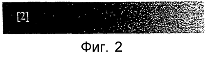
Фиг.2 представляет регистрацию в конфигурации, изображенной на фиг.1;Figure 2 represents the registration in the configuration depicted in figure 1;
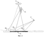
На фиг.3 представлена схема альтернативной конфигурации, согласно изобретению;Figure 3 presents a diagram of an alternative configuration according to the invention;
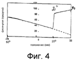
На фиг.4 представлен график зависимости флоп-угла от положения при регистрации в конфигурации, изображенной на фиг.3;Figure 4 presents a graph of the dependence of the flop angle on the position during registration in the configuration depicted in figure 3;
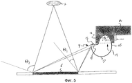
На фиг.5 представлена третья альтернативная конфигурация, согласно изобретению;5 shows a third alternative configuration according to the invention;
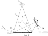
На фиг.6 представлена четвертая альтернативная конфигурация, согласно изобретению;6 shows a fourth alternative configuration according to the invention;
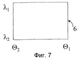
На фиг.7 представлено изменение фильтрованной длины волны в пределах образца, изображение которого сформировано устройством, изображенным на фиг.6;Figure 7 shows the change in the filtered wavelength within the sample, the image of which is formed by the device shown in Fig.6;
На фиг.8 представлен образец с параллельным эталонным образцом для измерения блеска.On Fig presents a sample with a parallel reference sample for measuring gloss.
На фиг.1 показано устройство 1, согласно настоящему изобретению, содержащее источник света 2, камеру 3 на ПЗС в качестве устройства регистрации, имеющую угол обзора (в пределах от направления наблюдения 4 первого внешнего конца, ближайшего к источнику света, до направления наблюдения 5 второго внешнего конца. Покрытый образец 6 расположен под камерой 3. Источник света 2 является линейным источником, параллельным поверхности образца. Источник света 2 расположен вне зоны прямого обзора камеры 3 на ПЗС. Линия между источником света 2 и точкой, где направление наблюдения 4 пересекается с образцом 6, задает первое направление освещения 7, которое отражается образцом 6 в направлении, заданном как первое направление отражения 8. Аналогично линия между источником света 2 и точкой, где направление наблюдения 5 пересекается с образцом 6, задает второе направление освещения 9, которое отражается образцом 6 в направлении, заданном как второе направление отражения 10. На фигуре, наружный флоп-угол Θ1 - это угол между первым направлением наблюдения 4 и первым направлением отражения 8, а наружный флоп-угол Θ2 - это угол между вторым направлением наблюдения 5 и вторым направлением отражения 10. Диапазон углов между Θ1 и Θ2 может составлять, примерно, до 90 градусов.Figure 1 shows the
На фиг.2 показано изображение, зарегистрированное в варианте осуществления, показанном на фиг.1. Это изображение образца, покрытого металлической краской. На этой фигуре показано, как меняется яркость с изменением флоп-угла. Изображение на фиг.2 также демонстрирует изменение зернистости вдоль образца, которое также воспринимается человеческим глазом.Figure 2 shows the image registered in the embodiment shown in figure 1. This is an image of a sample coated with metallic paint. This figure shows how the brightness changes with the flop angle. The image in figure 2 also shows the change in graininess along the sample, which is also perceived by the human eye.
На фиг.3 показана альтернативная конфигурация, согласно изобретению, где диапазон флоп-угла увеличен за счет использования зеркала 11. Зеркало 11 расположено таким образом, что в нем отражается часть образца, примыкающая справа к внешнему концу диапазона углов обзора камеры, наиболее удаленному от источника света 2. В изображении, наблюдаемом камерой 3, область охвата, ближайшая к источнику света 2, заменена продолжением области охвата на другой стороне. Справа налево регистрация показывает область охвата от Θ3 к Θ5, а затем область охвата от Θ4 к Θ2. Область охвата от Θ1 до Θ4 уже не видна на регистрации.Figure 3 shows an alternative configuration according to the invention, where the range of the flop angle is increased by using the
На фиг.4 показана зависимость флоп-угла от положения в конфигурации, аналогичной конфигурации, изображенной на фиг.3, причем положение 0 находится непосредственно под камерой. Отраженная от зеркала часть образца перекрывает часть примерно от 20 мм до 25 мм.Figure 4 shows the dependence of the flop angle on the position in a configuration similar to the configuration shown in figure 3, with
В необязательном порядке образец можно регистрировать в двух (или даже больше) отдельных параллельных полосках, одной - с областью охвата, расширенной с помощью зеркала, и другой - без нее. Таким образом, можно регистрировать полную увеличенную область охвата в пределах от Θ1 до Θ2 и область охвата в пределах от Θ5 до Θ3. Если Θ5 равен Θ2, то покрывается замкнутый диапазон от Θ1 до Θ3.Optionally, the sample can be recorded in two (or even more) separate parallel strips, one with a coverage area expanded with a mirror, and the other without it. Thus, it is possible to register a complete enlarged coverage area ranging from Θ 1 to Θ 2 and a coverage area ranging from Θ 5 to Θ 3 . If Θ 5 is Θ 2 , then the closed range from от 1 to Θ 3 is covered.
На фиг.5 показана конфигурация, аналогичная конфигурации, показанной на фиг.1, в которой камера 3 находится непосредственно над образцом 6, и источник света 12 содержит стандартный импульсный источник света 13, доступный под торговым знаком Metz 45CT-1. Импульсный источник света 13 содержит прозрачную сторону 14. На прозрачной стороне 14 импульсный источник света присоединен к плоской верхней стороне 15 рассеивателя 16, содержащего полуцилиндрическую деталь 17. Эта плоская сторона 15 открыта в месте соединения с прозрачной стороной 14 импульсного источника света 13. Внутренняя сторона рассеивателя 16 покрыта белым покрытием. Там, где она не совпадает с прозрачной стороной 14 импульсного источника света 13, плоская сторона 15 закрыта горизонтальной стенкой 18, внутренняя сторона которой снабжена белым покрытием. Край между наружным концом горизонтальной стенки 18 и полуцилиндрической деталью 17 снабжен вертикальной щелью 19, проходящей по ширине рассеивателя 16.Figure 5 shows a configuration similar to the configuration shown in figure 1, in which the
Когда импульсный источник света 13 вспыхивает, свет рассеивается отражающими покрытиями на внутренней стороне рассеивателя 16. Часть света отражается отражающим слоем горизонтальной стенки 18 через щель 19 на часть образца 6, для которой нужно сформировать изображение. Из фиг.5 видно, что на внешнем направлении обзора диапазона угла обзора камеры, ближайшем к рассеивателю 16, образец 6 освещается значительно меньшей частью отражающей горизонтальной стенки 17, чем на внешнем направлении обзора камеры, удаленном от рассеивателя 16. Таким образом, плотность света является функцией углового расстояния от источника света. Функция может изменяться в зависимости от ориентации щели по отношению к поверхности образца.When the pulsed
Стекловолоконный кабель 20 соединяет пространство, окружающее импульсный источник света 13, со светочувствительным устройством 21, управляющим интервалом времени, в течение которого происходит вспышка импульсного источника света 13. Часть света, рассеянного в рассеивателе 16, поступает через стекловолоконный кабель 20 на светочувствительное устройство 21. Светочувствительное устройство 21 измеряет количество света, прошедшего по стекловолоконному кабелю 20. Когда по стекловолоконному кабелю 20 проходит заданное количество света, светочувствительное устройство 21 блокирует импульсный источник света 13. Таким образом, можно гарантировать, что каждая вспышка дает абсолютно одинаковое количество света.A
На фиг.6 показан еще один альтернативный вариант осуществления устройства, отвечающего изобретению, содержащий устройство формирования изображения 3 и источник света 2. Образец 6 расположен под устройством формирования изображения 3. Между источником света 2 и образцом 6 находится набор фильтров и дифракционная решетка или призма 24. Спектральное распределение освещения изменяется в одном изображении как функция положения на образце. На фиг.7 показан результат предпочтительного варианта осуществления, где спектральное распределение освещения изменяется перпендикулярно изменению оптической геометрии.Fig. 6 shows another alternative embodiment of the device corresponding to the invention, comprising an
На фиг.8 показано, что поведение блеска образца можно характеризовать как функцию оптической геометрии. Этот частный пример показывает, в одном изображении, разницу между образцом 25 с высоким блеском и образцом 26 с низким блеском.On Fig shows that the gloss behavior of the sample can be characterized as a function of optical geometry. This particular example shows, in one image, the difference between the
Claims (9)
Applications Claiming Priority (2)
| Application Number | Priority Date | Filing Date | Title |
|---|---|---|---|
| EP01201276.1 | 2001-04-06 | ||
| EP01201276 | 2001-04-06 |
Publications (2)
| Publication Number | Publication Date |
|---|---|
| RU2003132476A RU2003132476A (en) | 2005-03-20 |
| RU2292037C2 true RU2292037C2 (en) | 2007-01-20 |
Family
ID=8180117
Family Applications (1)
| Application Number | Title | Priority Date | Filing Date |
|---|---|---|---|
| RU2003132476/28A RU2292037C2 (en) | 2001-04-06 | 2002-03-28 | Method of recording goniometric characteristics of paint-and-varnish film |
Country Status (9)
| Country | Link |
|---|---|
| EP (1) | EP1373867A1 (en) |
| JP (1) | JP3933581B2 (en) |
| KR (1) | KR100875806B1 (en) |
| CN (1) | CN100403011C (en) |
| AU (1) | AU2002338353B2 (en) |
| BR (1) | BR0208660A (en) |
| RU (1) | RU2292037C2 (en) |
| WO (1) | WO2002082063A1 (en) |
| ZA (1) | ZA200307712B (en) |
Families Citing this family (10)
| Publication number | Priority date | Publication date | Assignee | Title |
|---|---|---|---|---|
| GB0625890D0 (en) * | 2006-12-23 | 2007-02-07 | Colormatrix Holdings Inc | Polymeric materials |
| US9025153B2 (en) * | 2011-11-16 | 2015-05-05 | Axalta Coating Systems Ip Co., Llc | Process for predicting degree of mottling in coating compositions by wet color measurement |
| JP5475057B2 (en) | 2012-04-20 | 2014-04-16 | 株式会社 オフィス・カラーサイエンス | Variable angle spectroscopic imaging measurement method and apparatus |
| EP2847556A4 (en) * | 2012-05-09 | 2016-01-27 | Seagate Technology Llc | Surface features mapping |
| CN103674903A (en) * | 2013-12-31 | 2014-03-26 | 爱彼思(苏州)自动化科技有限公司 | Non-contact vancometer |
| US9880098B2 (en) * | 2014-10-28 | 2018-01-30 | Axalta Coatings Systems Ip Co., Llc | Method and systems for quantifying differences between colored surfaces |
| US9678018B2 (en) * | 2015-03-30 | 2017-06-13 | Gemological Institute Of America Inc. (Gia) | Apparatus and method for assessing optical quality of gemstones |
| CN106908149A (en) * | 2017-04-11 | 2017-06-30 | 上海电机学院 | A kind of robot object color identifying system and method |
| KR102047206B1 (en) * | 2018-10-31 | 2019-11-20 | 한국과학기술원 | Swcc-hyperspectral cam test method and apparatus for measuring reflectance by volumetric water content |
| JP7341835B2 (en) * | 2019-10-09 | 2023-09-11 | 株式会社日立製作所 | Powder mixing system and powder mixing method |
Family Cites Families (5)
| Publication number | Priority date | Publication date | Assignee | Title |
|---|---|---|---|---|
| JP2588297B2 (en) * | 1990-06-20 | 1997-03-05 | 日産自動車株式会社 | Evaluation method for sharpness of painted surface |
| US5078496A (en) * | 1990-08-14 | 1992-01-07 | Autospect, Inc. | Machine vision surface characterization system |
| US5640237A (en) * | 1995-08-29 | 1997-06-17 | Kla Instruments Corporation | Method and apparatus for detecting non-uniformities in reflective surafaces |
| JP3312849B2 (en) * | 1996-06-25 | 2002-08-12 | 松下電工株式会社 | Defect detection method for object surface |
| EP1016126B1 (en) * | 1997-03-31 | 2018-12-26 | Nanometrics Incorporated | Optical inspection module and method for detecting particles and defects on substrates in integrated process tools |
-
2002
- 2002-03-28 EP EP02742872A patent/EP1373867A1/en not_active Withdrawn
- 2002-03-28 RU RU2003132476/28A patent/RU2292037C2/en active
- 2002-03-28 JP JP2002579783A patent/JP3933581B2/en not_active Expired - Fee Related
- 2002-03-28 CN CNB028079019A patent/CN100403011C/en not_active Expired - Fee Related
- 2002-03-28 BR BR0208660-3A patent/BR0208660A/en not_active IP Right Cessation
- 2002-03-28 KR KR1020037012945A patent/KR100875806B1/en not_active IP Right Cessation
- 2002-03-28 WO PCT/EP2002/003682 patent/WO2002082063A1/en active Application Filing
- 2002-03-28 AU AU2002338353A patent/AU2002338353B2/en not_active Ceased
-
2003
- 2003-10-02 ZA ZA200307712A patent/ZA200307712B/en unknown
Also Published As
| Publication number | Publication date |
|---|---|
| BR0208660A (en) | 2004-03-09 |
| AU2002338353B2 (en) | 2006-05-25 |
| JP3933581B2 (en) | 2007-06-20 |
| KR100875806B1 (en) | 2008-12-26 |
| RU2003132476A (en) | 2005-03-20 |
| WO2002082063A1 (en) | 2002-10-17 |
| EP1373867A1 (en) | 2004-01-02 |
| CN100403011C (en) | 2008-07-16 |
| ZA200307712B (en) | 2004-07-06 |
| JP2004526969A (en) | 2004-09-02 |
| KR20040012743A (en) | 2004-02-11 |
| CN1505757A (en) | 2004-06-16 |
Similar Documents
| Publication | Publication Date | Title |
|---|---|---|
| JP6038965B2 (en) | Coloring inspection apparatus and coloring inspection method | |
| EP2840368B1 (en) | Variable angle spectroscopic imaging measurement method and device therefor | |
| US20100232688A1 (en) | Color chart processing apparatus, color chart processing method, and color chart processing program | |
| Liang et al. | A new multi-spectral imaging system for examining paintings | |
| CN102124723B (en) | Method and device for the true-to-original representation of colors on screens | |
| KR20120006940A (en) | Dental shade mapping | |
| FI124452B (en) | Method and apparatus for measuring color and other properties of a surface | |
| JP2002345760A (en) | Spectral reflectance measuring device | |
| RU2292037C2 (en) | Method of recording goniometric characteristics of paint-and-varnish film | |
| JP6371237B2 (en) | Coloring evaluation apparatus and coloring evaluation method | |
| US7990536B2 (en) | System and method for measuring reflectance of object | |
| US7027165B2 (en) | Method and device for surface evaluation | |
| JP7099474B2 (en) | Multi-angle colorimeter | |
| EP3594658A1 (en) | Evaluator, measurement apparatus, evaluating method, and evaluating program | |
| AU2002338353A1 (en) | Method and device for surface evaluation | |
| KR101129327B1 (en) | System and method for measuring reflectance based on image | |
| JP2016194449A (en) | Coloring checkup device, and coloring checkup method | |
| JP2006071316A (en) | Film thickness acquiring method | |
| JP3577977B2 (en) | Illumination light spectral characteristic estimation device | |
| Paviotti et al. | Multispectral acquisition of large-sized pictorial surfaces | |
| KR100809553B1 (en) | The Apparatus And Method for Image Quality Evaluation of Color Imaging Sensor | |
| JP2002350355A (en) | Evaluating device, evaluating method for unevenness of gloss and computer-readable storage medium storing program for this method | |
| Välisuo et al. | Reflectance measurement using digital camera and a protecting dome with built in light source | |
| JPH08114503A (en) | Colorimetry device | |
| FR2821671A1 (en) | Method for objective evaluation of the color and homogeneity of a surface, especially for evaluation and comparison of concrete facings, such that surfaces in different locations can be objectively compared |