RU2286880C2 - Folder with several driving engines - Google Patents
Folder with several driving engines Download PDFInfo
- Publication number
- RU2286880C2 RU2286880C2 RU2002104568/12A RU2002104568A RU2286880C2 RU 2286880 C2 RU2286880 C2 RU 2286880C2 RU 2002104568/12 A RU2002104568/12 A RU 2002104568/12A RU 2002104568 A RU2002104568 A RU 2002104568A RU 2286880 C2 RU2286880 C2 RU 2286880C2
- Authority
- RU
- Russia
- Prior art keywords
- cylinder
- engine
- folding
- valve
- sheets
- Prior art date
Links
Images
Classifications
-
- B—PERFORMING OPERATIONS; TRANSPORTING
- B65—CONVEYING; PACKING; STORING; HANDLING THIN OR FILAMENTARY MATERIAL
- B65H—HANDLING THIN OR FILAMENTARY MATERIAL, e.g. SHEETS, WEBS, CABLES
- B65H45/00—Folding thin material
- B65H45/12—Folding articles or webs with application of pressure to define or form crease lines
- B65H45/16—Rotary folders
- B65H45/162—Rotary folders with folding jaw cylinders
- B65H45/168—Rotary folders with folding jaw cylinders having changeable mode of operation
-
- B—PERFORMING OPERATIONS; TRANSPORTING
- B41—PRINTING; LINING MACHINES; TYPEWRITERS; STAMPS
- B41F—PRINTING MACHINES OR PRESSES
- B41F13/00—Common details of rotary presses or machines
- B41F13/004—Electric or hydraulic features of drives
- B41F13/0045—Electric driving devices
-
- B—PERFORMING OPERATIONS; TRANSPORTING
- B41—PRINTING; LINING MACHINES; TYPEWRITERS; STAMPS
- B41F—PRINTING MACHINES OR PRESSES
- B41F13/00—Common details of rotary presses or machines
- B41F13/54—Auxiliary folding, cutting, collecting or depositing of sheets or webs
- B41F13/56—Folding or cutting
- B41F13/62—Folding-cylinders or drums
Landscapes
- Engineering & Computer Science (AREA)
- Mechanical Engineering (AREA)
- Folding Of Thin Sheet-Like Materials, Special Discharging Devices, And Others (AREA)
Abstract
Description
Область техники, к которой относится изобретениеFIELD OF THE INVENTION
Настоящее изобретение относится в целом к печатным машинам и, в частности, к фальцмашине печатной машины.The present invention relates generally to printing presses and, in particular, to a press machine folding machine.
Предпосылки создания изобретенияBACKGROUND OF THE INVENTION
Ротационные (рулонные) печатные машины предназначены для запечатывания непрерывного полотна материала, в частности бумаги. В имеющейся в печатной машине фальцмашине непрерывное бумажное полотно разрезается на отдельные листы, которые затем фальцуются. В настоящее время известно много различных типов фальцмашин, одной из которых является комбинированная фальцмашина.Rotary (roll) printing machines are designed for sealing a continuous web of material, in particular paper. In a folding machine available in the printing press, a continuous paper web is cut into separate sheets, which are then folded. Currently, many different types of folding machines are known, one of which is a combined folding machine.
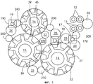
Обычно комбинированные фальцмашины состоят из группы цилиндров, которые выполняют определенные операции по окончательному формированию различных участков фальца, при этом каждый цилиндр может выполнять как одну, так и несколько операций. Изменяя относительное положение цилиндров в комбинированной фальцмашине, ее можно приспособить для обработки различных видов печатной продукции. На фиг.1 показана конструкция главного цилиндра комбинированной фальцмашины, в частности ее фальцевального цилиндра. Такая конструкция достаточно хорошо известна и на ее примере можно проиллюстрировать сущность настоящего изобретения. К валу 2 цилиндра первым и вторым рычагами 3 и 4 крепится первая рабочая часть 1, которая выполняет функции фальцевальной секции. На валу 2 установлены первая и вторая полые концентричные ступицы 5 и 6, оси которых совпадают с осью вала. К первой и второй полым ступицам 5 и 6 третьим и четвертым рычагами 8 и 9 крепится вторая рабочая часть 7 основного цилиндра, которая выполняет, например, функции участка листопроводящей системы с захватами. Вал 2 и обе ступицы 5 и 6 приводятся во вращение первым и вторым зубчатыми колесами 10 и 11 соответственно, которые жестко соединены между собой через косозубую зубчатую передачу и синхронно вращаются с соответствующей скоростью вокруг общей оси.Usually combined folding machines consist of a group of cylinders that perform certain operations to finally form various sections of the fold, with each cylinder performing one or several operations. By changing the relative position of the cylinders in the combination folding machine, it can be adapted to handle various types of printed products. Figure 1 shows the design of the main cylinder of a combined folding machine, in particular its folding cylinder. This design is well known and can be used to illustrate the essence of the present invention. The first working part 1, which performs the functions of the folding section, is attached to the shaft 2 of the cylinder by the first and second levers 3 and 4. On the shaft 2, the first and second hollow concentric hubs 5 and 6 are installed, the axes of which coincide with the axis of the shaft. The second working part 7 of the main cylinder is attached to the first and second hollow hubs 5 and 6 by the third and fourth levers 8 and 9, which performs, for example, the functions of a section of a sheet-conducting system with grippers. The shaft 2 and both hubs 5 and 6 are driven by the first and second gears 10 and 11, respectively, which are rigidly connected to each other through a helical gear transmission and synchronously rotate at a corresponding speed around a common axis.
В существующих комбинированных фальцмашинах часто требуется изменять вид фальцевания и поэтому они имеют пневмоцилиндры, которые соответствующим образом перемещают зубчатые колеса косозубой зубчатой передачи в необходимое положение. Синхронно вращающиеся косозубые зубчатые колеса обеспечивают синхронное вращение цилиндров, с корпусами которых они соединены шпоночными соединениями. В выполненной таким образом фальцмашине одна группа корпусов цилиндров синхронно вращается относительно другой группы корпусов цилиндров.In existing combination seals, it is often required to change the type of seaming and therefore they have pneumatic cylinders that accordingly move the gears of the helical gear transmission to the desired position. Synchronously rotating helical gears provide synchronous rotation of the cylinders, with the bodies of which they are connected by key connections. In a thus designed folding machine, one group of cylinder bodies rotates synchronously with respect to another group of cylinder bodies.
Недостатком такой конструкции фальцмашины с пневмоцилиндрами и косозубыми зубчатыми колесами является возможность перекоса или заедания зубчатых колес при изменении их относительного положения. Причиной такого перекоса или заедания зубчатых колес может служить большой вес корпусов цилиндров или прихватывание ступиц на валу из-за недостаточной смазки или фреттинг-коррозии.The disadvantage of this design of the folding machine with pneumatic cylinders and helical gears is the possibility of skewing or jamming of the gears when changing their relative position. The reason for such a skew or jamming of the gears can be the large weight of the cylinder bodies or the grabbing of the hubs on the shaft due to insufficient lubrication or fretting corrosion.
Во избежание возможного заедания зубчатых колес комбинированные фальцмашины приходится периодически останавливать для профилактического обслуживания. Очевидно, что такое обслуживание связано с определенными потерями времени и простоем фальцмашины.In order to avoid possible jamming of gears, the combined folding machines must be stopped periodically for preventative maintenance. Obviously, this service is associated with certain losses of time and downtime of the folding machine.
В патенте US 5405126 предложена фальцмашина, которая имеет по крайней мере первое устройство продольной фальцовки, несколько приводимых в движение разрезающих элементов и второе устройство продольной фальцовки, в которое фальцуемые копии подаются транспортерной лентой, расположенной над вторым приемно-выводным устройством. Фальцмашина имеет также вытягивающие устройства, расположенные в направлении длины бумажного полотна или копий до отделяющих элементов, первое приводное устройство, которое служит отдельным регулируемым приводом для отводящих устройств, и второе приводное устройство, которое служит приводом для отделяющих элементов и упомянутых устройств поперечной фальцовки. Кроме этого, фальцмашина имеет отдельный привод для упомянутых выше поворачиваемых наружу качающихся транспортерных лент. Второе продольное фальцовочное устройство состоит из ряда отдельных исполнительных элементов, в качестве привода которых используется отдельный фазоуправляемый электродвигатель. Второе приводное устройство выполнено в виде электродвигателя.US Pat. No. 5,405,126 proposes a folding machine that has at least a first longitudinal folding device, several driven cutting elements and a second longitudinal folding device, into which the folded copies are fed by a conveyor belt located above the second receiving and output device. The folding machine also has drawers located in the length direction of the paper web or copies to the separating elements, a first drive device that serves as a separate adjustable drive for the removal devices, and a second drive device that serves as a drive for the separating elements and the said transverse folding devices. In addition, the folding machine has a separate drive for the aforementioned swinging conveyor belts mentioned above. The second longitudinal folding device consists of a number of separate actuating elements, the drive of which uses a separate phase-controlled electric motor. The second drive device is made in the form of an electric motor.
Электродвигатель через один из режущих или отделяющих цилиндров приводит во вращение зубчатую передачу. Через эту зубчатую передачу приводной двигатель приводит во вращение фальцевальный цилиндр (или ножевой цилиндр клапанного фальцаппарата) и уже от него - клапанный цилиндр, а затем и цилиндр с захватами. Кроме того, приводное устройство второго продольного фальцующего устройства также можно выполнить в виде электродвигателя.An electric motor drives a gear train through one of the cutting or separating cylinders. Through this gear transmission, the drive motor drives the folding cylinder (or knife cylinder of the valve folder) and, from it, the valve cylinder, and then the cylinder with grippers. In addition, the drive device of the second longitudinal folding device can also be made in the form of an electric motor.
Недостаток предложенной в патенте US 5405126 фальцмашины состоит в том, что ее фальцевальный цилиндр, клапанный цилиндр и цилиндр с захватами приводятся во вращение от одного и того же привода, что, как очевидно, затрудняет возможность регулирования и перехода с одного вида фальцевания на другой.A drawback of the folding machine proposed in US Pat. No. 5,405,126 is that its folding cylinder, valve cylinder and cylinder with grippers are driven from the same drive, which, obviously, makes it difficult to control and switch from one type of folding to another.
В заявке ЕР 0699524 А2 предложена печатная секция с элементами, приводимыми в движение взаимосвязанными электродвигателями, обозначенными на чертежах буквой М. Каждое фальцевальное устройство, показанное на фиг.22 этой публикации, имеет свой отдельный приводной двигатель, который напрямую соединен с фальцевальными цилиндрами фальцевальных устройств. Недостаток печатной секции, предложенной в ЕР 0699524 А2, состоит в том, что все фальцевальные цилиндры ее фальцмашины приводятся во вращение одним и тем же двигателем, что создает определенные проблемы в изменении фазы.EP 0699524 A2 proposes a printing section with elements driven by interconnected electric motors indicated by M in the drawings. Each folding device shown in FIG. 22 of this publication has its own separate drive motor that is directly connected to the folding cylinders of the folding devices. The disadvantage of the printing section proposed in EP 0699524 A2 is that all of the folding cylinders of the folding machine are driven by the same motor, which creates certain problems in the phase change.
КРАТКОЕ ИЗЛОЖЕНИЕ СУЩНОСТИ ИЗОБРЕТЕНИЯSUMMARY OF THE INVENTION
В основу настоящего изобретения была положена задача разработать способ и устройство для упрощения регулирования группы клапанов фальцевального цилиндра и изменения вида фальцевания. Дополнительной или альтернативной задачей настоящего изобретения является разработка состоящего из нескольких электродвигателей привода комбинированной фальцмашины.The present invention was based on the task of developing a method and apparatus for simplifying the regulation of a group of valves of a folding cylinder and changing the type of folding. An additional or alternative objective of the present invention is to provide a combination folding machine drive consisting of several electric motors.
Под термином "захват" или "клапан" цилиндра фальцмашины в контексте настоящего описания понимается захватывающее или удерживающее устройство любого типа, предназначенное для захвата или удержания листов, в частности захват, удерживающий лист за заднюю кромку, или клапан.The term “grasping” or “valve” of a cylinder of a folder in the context of the present description refers to a gripping or holding device of any type designed to grasp or hold sheets, in particular a gripper holding the sheet by the trailing edge, or a valve.
В настоящем изобретении предлагается фальцмашина, имеющая первый цилиндр, по крайней мере, с одним первым захватом для удержания листов и, по крайней мере, с одним ножом, предназначенным для вдавливания листов и образования первого сгиба, второй цилиндр, по крайней мере, с одним клапаном, взаимодействующим, по крайней мере, с одним ножом для удержания сфальцованных листов у первого сгиба, первый двигатель для привода, по крайней мере, одного первого параллельного захвата, и второй двигатель, который выполнен отдельно от первого двигателя и служит для привода, по крайней мере, одного ножа первого цилиндра и, по крайней мере, одного первого клапана второго цилиндра.The present invention provides a folding machine having a first cylinder with at least one first grip for holding sheets and at least one knife for pressing sheets and forming a first fold, a second cylinder with at least one valve interacting with at least one knife to hold folded sheets at the first fold, the first engine for driving at least one first parallel grip, and a second engine, which is made separately from the first engine and Used for driving at least one of the first knife cylinder and at least one first valve of the second cylinder.
Наличие в предлагаемой в изобретении фальцмашине двух разных приводных двигателей позволяет изменять фазу между, по крайней мере, одним первым захватом и, по крайней мере, одним ножом и выбирать место расположения сгиба, а тем самым и шлейфа за счет изменения взаимного углового положения двух приводных двигателей. В отличие от фальцмашин с одним приводным двигателем предлагаемая в изобретении фальцмашина с двумя приводными двигателями вообще не имеет никаких сложных зубчатых передач, муфт или пневмоцилиндров. Кроме того, наличие второго приводного двигателя, который служит приводом ножа первого цилиндра и первого клапана второго цилиндра, позволяет отказаться от жесткой связи между ножом и клапаном и первым захватом и режущими цилиндрами и устранить влияние на них возникающего при резке бумажного полотна мгновенного изменения крутящего момента. За счет этого можно, как очевидно, ужесточить допуски на расположение фальцев и повысить точность фальцовки.The presence in the proposed invention of a folding machine of two different drive motors allows you to change the phase between at least one first grip and at least one knife and choose the location of the bend, and thereby the loop by changing the relative angular position of the two drive motors . In contrast to the single-drive folder machines, the two-drive folder machine of the invention does not have any complicated gears, couplings or pneumatic cylinders in general. In addition, the presence of a second drive motor, which serves as the drive of the knife of the first cylinder and the first valve of the second cylinder, allows you to abandon the rigid connection between the knife and the valve and the first grip and the cutting cylinders and eliminate the effect of instantaneous torque changes during cutting of the paper web. Due to this, you can obviously tighten the tolerances on the location of the folds and increase the accuracy of folding.
Наличие в предлагаемой фальцмашине двух приводных переключаемых двигателей облегчает переход с одного режима фальцовки на другой, например переход с поперечной фальцовки на дельтаобразную двухсгибную фальцовку.The presence in the proposed folding machine of two driven switching motors facilitates the transition from one folding mode to another, for example, the transition from transverse folding to a delta-shaped double-fold folding.
Первый двигатель можно также использовать для привода по крайней мере одной пары режущих цилиндров, предпочтительно двух пар режущих цилиндров, которые можно соединить фазирующим устройством с первыми захватами. Такая конструкция обеспечивает возможность изменения фазы между режущими цилиндрами и первыми захватами.The first engine can also be used to drive at least one pair of cutting cylinders, preferably two pairs of cutting cylinders, which can be connected by a phasing device to the first jaws. This design allows phase change between the cutting cylinders and the first grippers.
Для изменения фазы между ножами и первыми клапанами их можно соединить между собой фазирующим устройством или фазирующим центром. Изменение фазы между группой клапанов и ножами позволяет изменять положение группы клапанов относительно ножей.To change the phase between the knives and the first valves, they can be interconnected by a phasing device or a phasing center. Changing the phase between the valve group and the knives allows you to change the position of the valve group relative to the knives.
В качестве приводных двигателей предпочтительно использовать синхронные электродвигатели переменного тока, которые допускают возможность их регулирования во время работы. Один из приводных двигателей можно выполнить в виде главного (опорного или нерегулируемого) приводного двигателя, а другой - в качестве двигателя, регулируемого по отношению к главному двигателю.As drive motors, it is preferable to use synchronous AC motors, which allow the possibility of their regulation during operation. One of the drive motors can be made in the form of the main (reference or unregulated) drive motor, and the other as the engine, regulated in relation to the main engine.
В предпочтительном варианте в настоящем изобретении предлагается фальцмашина, имеющая режущие цилиндры для рубки полотна на листы, первый цилиндр, по крайней мере, с одним первым захватом для удержания листов за переднюю кромку и, по крайней мере, с одним ножом для вдавливания листов с образованием первого сгиба, второй цилиндр, по крайней мере, с одним первым клапаном для удержания сфальцованных листов у первого сгиба и, по крайней мере, с одним вторым клапаном для удержания сфальцованных листов у второго сгиба, третий цилиндр, по крайней мере, с одним вторым захватом для удержания сфальцованных листов у первого сгиба и, по крайней мере, с одним вторым ножом для образования второго сгиба, первый двигатель для привода режущих цилиндров и, по крайней мере, одного первого захвата, второй двигатель, который выполнен отдельно от первого двигателя и служит для привода, по крайней мере, одного ножа первого цилиндра, по крайней мере, одного первого клапана второго цилиндра и по крайней мере, одного второго захвата третьего цилиндра, и третий двигатель, который выполнен отдельно от первого и второго двигателей и служит для привода, по крайней мере, одного второго клапана второго цилиндра и по крайней мере одного второго ножа третьего цилиндра.In a preferred embodiment, the present invention provides a folding machine having cutting cylinders for cutting the web into sheets, a first cylinder with at least one first grip to hold the sheets by the leading edge and with at least one knife for pressing the sheets to form the first fold, a second cylinder with at least one first valve to hold the folded sheets at the first fold and at least one second valve to hold the folded sheets at the second fold, the third cylinder, at least Here, with one second grip to hold folded sheets at the first bend and at least one second knife to form a second bend, the first engine to drive the cutting cylinders and at least one first grip, a second engine, which is made separately from the first engine and serves to drive at least one knife of the first cylinder, at least one first valve of the second cylinder and at least one second capture of the third cylinder, and a third engine, which is made separately from of the second and second engines and serves to drive at least one second valve of the second cylinder and at least one second knife of the third cylinder.
Режущие цилиндры и захваты образуют в фальцмашине первый замкнутый контур вращения, первый нож и первый клапан вместе со вторым захватом образуют второй замкнутый контур вращения, а второй нож и второй клапан образуют третий замкнутый контур вращения.The cutting cylinders and grippers form the first closed rotation loop in the machine, the first knife and the first valve together with the second gripper form the second closed rotation loop, and the second knife and the second valve form the third closed rotation loop.
При наличии в предлагаемой в настоящем изобретении фальцмашине трех замкнутых контуров вращения взаимное расположение ножей и клапанов не зависит от работы режущих цилиндров, и поэтому резкое увеличение крутящего момента в момент рубки или резки листа происходит только в первом замкнутом контуре. Кроме того, в выполненной таким образом фальмашине образование сгиба не зависит в отличие от обычных фальцмашин от процесса резки листа, что позволяет ужесточить допуски на расположение сгибов в сфальцованном листе.If there are three closed circuits of rotation in the proposed machine in the present invention, the relative position of the knives and valves does not depend on the operation of the cutting cylinders, and therefore, a sharp increase in torque at the time of cutting or cutting of the sheet occurs only in the first closed circuit. In addition, the bending formation in the thus-made folding machine does not, unlike conventional folding machines, depend on the sheet cutting process, which makes it possible to tighten the tolerances on the location of the folds in the folded sheet.
В каждом замкнутом контуре предпочтительно обеспечить синхронное вращение функционально связанных между собой элементов, в частности синхронизировать друг с другом первую пару режущих цилиндров, вторую пару режущих цилиндров и первый захват, синхронизировать первый нож, первый клапан (второй захват) и четвертый захват, а также синхронизировать второй нож и второй клапан (третий захват), кинематически соединив их для этого между собой входящими в зацепление зубчатыми колесами.In each closed loop, it is preferable to synchronize the rotation of functionally interconnected elements, in particular to synchronize with each other the first pair of cutting cylinders, the second pair of cutting cylinders and the first grip, synchronize the first knife, the first valve (second grip) and the fourth grip, and also synchronize the second knife and the second valve (third grip), kinematically connecting them for this to each other with the gears engaging.
Изменяя фазу между вращением второго замкнутого контура и вращением первого замкнутого контура и фазу между вращением третьего замкнутого контура и вращением второго и первого контуров, можно регулировать взаимное расположение функционально связанных между собой устройств разных контуров. Тем самым создается возможность для быстрого, не связанного с большими затратами времени регулирования шлейфа и вида фальцевания. Для расширения возможностей для такого регулирования, например регулирования группы клапанов, можно использовать встроенные в каждый замкнутый контур фазирующие центры и промежуточные шестерни. Возможность такого регулирования позволяет использовать предлагаемую в изобретении фальцмашину для изготовления различной печатной продукции. Так, в частности, регулирование шлейфа позволяет выпускать печатную продукцию с разной длиной шлейфа, а регулирование группы клапанов позволяет менять толщину фальцуемых листов. Изменение режима фальцевания, например переход с двухсгибной параллельной фальцовки на дельтаобразную двухсгибную фальцовку, может быть реализовано также путем изменения углового положения элементов второго замкнутого контура относительно элементов первого замкнутого контура и углового положения элементов третьего и второго контуров относительно элементов первого контура.By changing the phase between the rotation of the second closed loop and the rotation of the first closed loop and the phase between the rotation of the third closed loop and the rotation of the second and first loops, it is possible to adjust the relative position of the devices of different loops that are functionally interconnected. This creates the opportunity for quick, not related to the large cost of time regulation loop and type of folding. To expand the possibilities for such regulation, for example regulation of a group of valves, it is possible to use the phasing centers and intermediate gears integrated in each closed loop. The possibility of such regulation allows the use of a folding machine according to the invention for the manufacture of various printed products. So, in particular, loop control allows you to produce printed products with different loop lengths, and regulation of the valve group allows you to change the thickness of the folded sheets. Changing the folding mode, for example, switching from a two-fold parallel folding to a delta-shaped two-folding folding, can also be realized by changing the angular position of the elements of the second closed loop relative to the elements of the first closed loop and the angular position of the elements of the third and second loops relative to the elements of the first loop.
Первый замкнутый контур может иметь опорную точку, предпочтительно образованную захватом, относительно которой задается фаза всех остальных функциональных элементов первого и других контуров. В другом варианте фазу элементов первого и третьего контуров можно задавать относительно элементов второго контура или фазу элементов первого и второго контуров можно задавать относительно элементов третьего контура, однако такие решения требуют при изменении линии реза запечатанного листа дополнительного перемещения отдельных деталей фальцмашины.The first closed loop may have a reference point, preferably formed by a grip, relative to which the phase of all other functional elements of the first and other loops is defined. In another embodiment, the phase of the elements of the first and third circuits can be set relative to the elements of the second circuit or the phase of the elements of the first and second circuits can be set relative to the elements of the third circuit, however, such solutions require additional movement of individual parts of the folding machine when changing the cutting line of the sealed sheet.
Для простых видов фальцовки предпочтительно использовать два контура, выполнив для этого функциональные элементы одного из трех контуров, например третьего, съемными.For simple types of folding, it is preferable to use two circuits, having made for this the functional elements of one of the three circuits, for example the third, removable.
Преимущество предлагаемой в изобретении фальцмашины с двумя контурами состоит в ее меньшей чувствительности к механическим повреждениям и меньшей стоимости благодаря отсутствию в ней лишних узлов и деталей. В качестве всех трех приводных двигателей предпочтительно использовать синхронные электродвигатели переменного тока, соединенные с соответствующими функциональными элементами зубчатыми передачами. Синхронные электродвигатели позволяют достаточно просто синхронизировать работу всех трех контуров и могут при этом развивать необходимую мощность. Каждый синхронный электродвигатель можно напрямую соединить с одним из функциональных устройств фальцмашины, например с зубчатым колесом крестовины первых захватов, с зубчатым колесом крестовины первых ножей, с зубчатым колесом крестовины вторых захватов (первых клапанов), с зубчатым колесом крестовины третьих захватов (вторых клапанов), с зубчатым колесом крестовины вторых ножей или с зубчатым колесом крестовины четвертых захватов, передавая через эти зубчатые колеса мощность к самим функциональным регулирующим устройствам. Такой подвод мощности непосредственно к функциональным элементам машины уменьшает количество промежуточных деталей привода и снижает связанные с трением потери крутящего момента двигателя.An advantage of the dual-circuit folder proposed in the invention is its lower sensitivity to mechanical damage and lower cost due to the absence of extra assemblies and parts. As all three drive motors, it is preferable to use synchronous AC motors connected to the corresponding functional elements by gears. Synchronous electric motors allow you to simply synchronize the operation of all three circuits and can at the same time develop the necessary power. Each synchronous electric motor can be directly connected to one of the functional devices of the folding machine, for example, with the gear wheel of the cross of the first grips, with the gear of the cross of the first grips, with the gear of the cross of the second grips (first valves), with the gear of the cross of the third grippers (second valves), with a gear wheel of a cross of the second knives or with a gear of a cross of a fourth captures, transmitting power through these gears to the functional regulating devices themselves. This power supply directly to the functional elements of the machine reduces the number of intermediate drive parts and reduces friction-related loss of engine torque.
По крайней мере, один из приводных двигателей предпочтительно установить непосредственно на фундаменте в определенном положении относительно рамы фальцмашины, повысив тем самым ее устойчивость и облегчив возможность изменения взаимного углового положения ее рабочих элементов.At least one of the drive motors is preferably installed directly on the foundation in a certain position relative to the frame of the folding machine, thereby increasing its stability and facilitating the possibility of changing the mutual angular position of its working elements.
Для изменения взаимного углового положения первого, второго и третьего контуров в предлагаемой в изобретении фальцмашине можно также использовать подвижную платформу с приводом. Наличие в фальцмашине такой платформы расширяет ее возможности и облегчает работу оператора при изменении режима фальцевания.To change the mutual angular position of the first, second and third circuits, a movable platform with a drive can also be used in the proposed machine. The presence of such a platform in the folding machine expands its capabilities and facilitates the work of the operator when changing the folding mode.
Для согласованной (по фазе) работы отдельных элементов каждого контура во всех трех контурах предпочтительно использовать встроенные в них фазирующие центры, выполненные, в частности, в виде сдвоенной зубчатой передачи с комплектом сменных зубчатых колес, предназначенных для изменения фазы между входящими с ними в зацепление зубчатыми колесами, и промежуточные шестерни.For the coordinated (in phase) operation of the individual elements of each circuit in all three circuits, it is preferable to use the phasing centers built in them, made, in particular, in the form of a double gear transmission with a set of interchangeable gears designed to change the phase between the gears that come into contact with them wheels, and intermediate gears.
В другом варианте изобретения предлагаемая в нем фальцмашина содержит четыре отдельных приводных двигателя, один из которых используется для привода режущих цилиндров, а другой, независимый от первого, - для привода первых захватов. Второй и третий контуры имеют свои отдельные приводные двигатели.In another embodiment of the invention, the proposed folding machine comprises four separate drive motors, one of which is used to drive the cutting cylinders, and the other, independent of the first, to drive the first grippers. The second and third circuits have their own separate drive motors.
В настоящем изобретении предлагается также способ резки и фальцевания печатной продукции, заключающийся в том, что приводят в движение первым двигателем первый замкнутый контур, в котором происходит резка материала на листы и их перемещение к первому захвату, приводят в движение вторым двигателем второй замкнутый контур, в котором листы вдавливаются в первый клапан и перемещаются ко второму захвату, и приводят в движение третьим двигателем третий замкнутый контур, в котором листы вдавливаются во второй клапан.The present invention also proposes a method for cutting and folding of printed products, which consists in driving the first closed loop in the first motor, in which the material is cut into sheets and moving to the first grip, in driving the second closed loop in the second motor, wherein the sheets are pressed into the first valve and moved to the second grip, and a third closed loop is driven by the third engine, in which the sheets are pressed into the second valve.
Предпочтительно предлагаемый в изобретении способ предусматривает возможность изменения фазы между, по крайней мере, первым и вторым контурами для установки длины шлейфа и изменения вида фальцовки.Preferably, the inventive method provides for the possibility of changing the phase between at least the first and second circuits to set the length of the loop and change the type of folding.
Изменение фазы предпочтительно выполняется во время работы машины и исключает необходимость остановки и простоя машины.The phase change is preferably performed during operation of the machine and eliminates the need to stop and stop the machine.
В настоящем изобретении предлагается также фальцмашина, имеющая первый цилиндр с первым функциональным устройством и вторым функциональным устройством и второй цилиндр с третьим функциональным устройством, работающим совместно со вторым функциональным устройством. В качестве привода первого функционального устройства используется первый двигатель, а в качестве привода второго и третьего функциональных устройств - второй, независимый от первого двигатель.The present invention also provides a folding machine having a first cylinder with a first functional device and a second functional device and a second cylinder with a third functional device working in conjunction with the second functional device. The first engine is used as the drive of the first functional device, and the second engine independent of the first is used as the drive of the second and third functional devices.
КРАТКОЕ ОПИСАНИЕ ЧЕРТЕЖЕЙBRIEF DESCRIPTION OF THE DRAWINGS
Ниже изобретение более подробно рассмотрено на примере предпочтительного варианта его осуществления со ссылкой на прилагаемые чертежи, на которых показано:Below the invention is described in more detail on the example of a preferred variant of its implementation with reference to the accompanying drawings, which show:
на фиг.1 - схема конструктивного выполнения главного цилиндра известной комбинированной фальцмашины,figure 1 - diagram of a structural embodiment of the main cylinder of the known combined folding machines,
на фиг.2 - схема предлагаемой в изобретении комбинированной фальцмашины, показанной со стороны зубчатой передачи, иfigure 2 - scheme proposed in the invention of a combined folding machine shown from the side of the gear transmission, and
на фиг.3 - схема показанной на фиг.2 фальцмашины с более подробным изображением ее приводных элементов.figure 3 is a diagram shown in figure 2 of a folding machine with a more detailed image of its drive elements.
ПРЕДПОЧТИТЕЛЬНЫЙ ВАРИАНТ ВЫПОЛНЕНИЯ ИЗОБРЕТЕНИЯBEST MODE FOR CARRYING OUT THE INVENTION
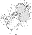
На фиг.2 схематично в виде сбоку показана выполненная в соответствии с предпочтительным вариантом комбинированная фальцмашина с тремя приводными двигателями. Эта фальцмашина имеет первую пару режущих цилиндров 12 и вторую пару режущих цилиндров 13, которые предназначены для резки или рубки бумажного полотна на отдельные листы. Отрезанный лист попадает на подборочный цилиндр 14, в котором один из нескольких первых захватов 32 захватывают этот лист за переднюю кромку. Далее лист поворачивается на подборочном цилиндре 14 и проходит к первому фальцевальному цилиндру 15. В тот момент, когда первый захват 32 освобождает переднюю кромку листа, один из нескольких ножей 37 подборочного цилиндра 14 вдавливает среднюю часть листа в один из нескольких клапанов 38 первого фальцевального цилиндра 15.Figure 2 schematically in side view shows made in accordance with the preferred embodiment of the combined folder with three drive motors. This folding machine has a first pair of cutting
После этого новой передней кромкой поперечной согнутого листа становится его первый сгиб, который удерживается первым клапаном 38 первого фальцевального цилиндра 15. При вращении фальцевального цилиндра 15 сфальцованный лист (тетрадь) подходит ко второму фальцевальному цилиндру 16, в котором один из вторых захватов захватывает лист за новую переднюю кромку (за первый сгиб) и поворачивает этот лист вокруг цилиндра 16. При повороте листа один из вторых ножей 46 вдавливает новую среднюю часть уже однократно сфальцованного листа в один из вторых клапанов 47 первого фальцевального цилиндра 15. После освобождения из вторых клапанов 47 листы, сфальцованные в два параллельных сгиба, попадают затем на соответствующий транспортер, который перемещает их к следующему узлу печатной машины.After this, the first leading edge of the transverse bent sheet becomes its first bend, which is held by the
Предлагаемая в настоящем изобретении фальцмашина приводится в действие через три ведущие шестерни 17, 18 и 19 тремя отдельными двигателями 170, 180 и 190 соответственно. На фиг.2 и 3 изображены различные элементы привода фальцмашины, схема которой показана на фиг.2. Ведущая шестерня 17 входит в зацепление с фазирующим центром 20, который приводит во вращение зубчатое колесо крестовины первых захватов 32. Возможность вращения первых захватов 32 только в одном направлении и высокая точность фальцовки обеспечиваются наличием беззазорной шестерни 23, которая удерживает зубчатые колеса в зацеплении. Ведущая шестерня 17 входит также в зацепление с промежуточной шестерней 200, через которую она приводит во вращение первую пару 13 режущих цилиндров, которые в свою очередь через откидную шестерню 26 приводят во вращение вторую пару режущих цилиндров 12. Таким образом, ведущая шестерня 17 приводит во вращение все элементы первого замкнутого контура, включающего две пары режущих цилиндров 12 и 13 и первые захваты 32 подборочного цилиндра 14. Наличие в приводе фазирующего центра 20, который выполнен в виде сдвоенной зубчатой передачи с комплектом сменных зубчатых колес, с помощью которых можно изменять фазу между входящими с ними в зацепление зубчатыми колесами, и промежуточной шестерни 200, позволяет менять фазу между первой парой режущих цилиндров 12 и первыми захватами 32.The present machine in the present invention is driven through three drive gears 17, 18 and 19 by three
Вторая ведущая шестерня 18 входит в зацепление с зубчатым колесом крестовины ножей 37. Через промежуточную шестерню 210 и фазирующий центр 21 приводятся во вращение первые клапаны 38, расположенные на концах соответствующей крестовины. В свою очередь первые клапаны 38 приводят во вращение вторые захваты 39. Кинематическое замыкание второго приводного контура осуществляется через промежуточную шестерню 230 и беззазорную шестерню 25, которые соединяют зубчатое колесо крестовины вторых захватов 39 со второй ведущей шестерней.The
Таким образом, вторая ведущая шестерня 18 приводит во вращение все элементы второго замкнутого контура, включающего расположенные на соответствующих крестовинах первые ножи 37, первые клапаны 38 и вторые захваты 39.Thus, the
Ведущая шестерня 19 приводит во вращение промежуточную шестерню 240, которая в свою очередь приводит во вращение вторые ножи 46. Вращение вторых ножей 46 передается через фазирующий центр 22 и промежуточную шестерню 220 вторым клапанам 47. Вторые клапаны 47 через промежуточную шестерню 250 и беззазорную шестерню 24 соединены с ведущей шестерней 19 и замыкают третий приводной контур.The
Таким образом, третий приводной замкнутый контур, который приводится во вращение ведущей шестерней 19, включает вторые клапаны 47 и вторые ножи 46.Thus, the third closed drive circuit, which is driven by the
В качестве приводных двигателей 170, 180 и 190 предпочтительно использовать синхронные электродвигатели переменного тока, которые обладают высокой чувствительностью, легко регулируются во время работы и эффективно поддерживают заданную скорость при изменении нагрузки. В наиболее предпочтительном варианте один конец одного или нескольких приводных двигателей надежно фиксируется относительно основания фальцмашины.As the
Каждый приводной замкнутый контур с соответствующей приводной шестерней 17, 18 и 19 обеспечивает выполнение одной или нескольких операций фальцовки. В состав первого приводного контура входят первая и вторая пары режущих цилиндров 12 и 13, которые осуществляют резку листа, а также первые захваты 32, которые осуществляют первый захват листа, в состав второго приводного контура входят первые ножи 37 и первые клапаны 38, которые образуют первый сгиб листа и перемещают его ко вторым захватам 39, а в состав третьего приводного контура входят вторые ножи 46, которые вместе со вторыми клапанами 47 образуют второй сгиб листа.Each closed drive circuit with a
Если операция резки не связана с другими выполняемыми фальцмашиной операциями, то первый захват листа связан с выполнением других операций, поскольку при перемещении листа его передняя кромка должна быть расположена точно под одним из первых захватов 32. Начиная с момента образования первого сгиба до момента второго захвата листа первые ножи 37, первые клапаны 38 и вторые захваты 39 должны находиться в строго заданном друг относительно друга положении, поскольку когда один из первых ножей 37 сгибает лист, один из первых клапанов 38 должен находиться в положении приема листа, а когда первый клапан 38 затем освобождает лист, один из вторых захватов 39 должен находиться в положении приема листа. Кроме того, работа вторых клапанов 47 также взаимосвязана с работой вторых ножей 46, поскольку когда при образовании второго сгиба один из вторых ножей 46 подходит к рабочему положению, один из вторых клапанов 47 должен находиться в положении приема.If the cutting operation is not related to other operations performed by the folding machine, then the first grip of the sheet is associated with other operations, since when moving the sheet, its leading edge should be located exactly under one of the first grabs 32. From the moment the first fold is formed until the second grip of the sheet the
Наличие в предлагаемой в изобретении фальцмашине трех независимых приводных контуров создает определенную свободу при согласовании одной группы операций с другой группой операций, при этом, например, изменение положения первых ножей 37 относительно первых захватов 32, от которого зависит длина шлейфа, можно регулировать, не меняя при этом фазы между первыми ножами 37 и первыми клапанами 38. При регулировании длины шлейфа происходит изменение положения передней кромки листа относительно его задней кромки, с которой передняя кромка совмещается после фальцовки. Благодаря наличию фазирующего центра 21 регулировкой группы клапанов второго замкнутого контура можно оптимизировать перенос листа между ножами 37 и клапанами 38 и менять при необходимости толщину печатной продукции.The presence of three independent drive loops in the invented folding machine creates a certain freedom when coordinating one group of operations with another group of operations, while, for example, changing the position of the
При регулировании шлейфа первого фальца первые ножи 37 перемещаются из номинального положения относительно первых захватов 32. При наличии в предлагаемой в изобретении фальцмашине приводных двигателей 170, 180, которые приводят во вращение первую и вторую ведущие шестерни 17, 18, и при соответствующем согласовании скорости вращения второго двигателя и скорости вращения первого двигателя положение первых ножей 37 относительно первых параллельных захватов 32 можно менять, сохранив при этом должное взаимное положение вторых захватов 39 и первых ножей 37. В предлагаемой в изобретении фальцмашине при переносе листа первые ножи 37, первые захваты 32, первые клапаны 38 и вторые захваты 39 будут всегда находиться в соответствующих положениях. Тем самым создается возможность для изменения относительного положения передней кромки сходящего с подборочного цилиндра 14 листа и образующегося на нем сгиба. Кроме того, увеличивая расстояние между первыми ножами 37 и первыми захватами 32, можно изменять вид фальцевания, переходя, например, на дельтаобразную двухсгибную фальцовку.When adjusting the loop of the first rebate, the
Регулирование шлейфа второго сгиба можно обеспечить за счет перемещения третьего приводного контура относительно второго приводного контура. Регулирование шлейфа второго сгиба, которое, по существу, не отличается от регулирования шлейфа первого сгиба, осуществляется путем соответствующего согласования скорости вращения третьего приводного двигателя и скорости вращения второго приводного двигателя. Наличие в третьем замкнутом контуре фазирующего центра 24 позволяет регулировать входящие в состав этого контура клапаны фальцевального цилиндра.The loop control of the second fold can be achieved by moving the third drive circuit relative to the second drive circuit. The control of the plume of the second bend, which essentially does not differ from the regulation of the plume of the first bend, is carried out by matching the rotation speed of the third drive motor and the rotation speed of the second drive motor. The presence of a
В состав каждого из трех отдельных приводных контуров входит один из трех приводных двигателей 170, 180, 190, один из трех фазирующих центров 20, 21, 22, одна из трех беззазорных шестерен 23, 24, 25 и, по крайней мере, одна из промежуточных шестерен 200, 210, 230, 240, 220, 250. Беззазорные шестерни 23, 24, 25 и фазирующие центры 20, 21, 22 предпочтительно выполнять в виде набора сменных косозубых колес с передаточным отношением 1:1 и противоположными углами наклона зубьев.Each of the three separate drive circuits includes one of three
В каждом из трех приводных контуров крутящий момент передается через все элементы фальцмашины, входящие в состав соответствующего замкнутого контура, который начинается и заканчивается одной и той же ведущей шестерней 17, 18 или 19.In each of the three drive circuits, the torque is transmitted through all the elements of the folding machine, which are part of the corresponding closed circuit, which begins and ends with the
Первый, второй и/или третий замкнутый контур можно использовать в приводе фальцевальной секции, в которой лист сгибается посередине в два слоя фальцевальной секции, в которой лист сгибается в 1/4, и/или в приемно-выводной секции.The first, second and / or third closed loop can be used in the drive of the folding section, in which the sheet is bent in the middle into two layers of the folding section, in which the sheet is bent in 1/4, and / or in the receiving-output section.
Claims (14)
Applications Claiming Priority (3)
| Application Number | Priority Date | Filing Date | Title |
|---|---|---|---|
| US09/795,075 | 2001-02-23 | ||
| US09/795,075 US6752751B2 (en) | 2001-02-23 | 2001-02-23 | Folder with multiple-motor drive |
| US795,075 | 2001-02-23 |
Publications (2)
| Publication Number | Publication Date |
|---|---|
| RU2002104568A RU2002104568A (en) | 2003-11-27 |
| RU2286880C2 true RU2286880C2 (en) | 2006-11-10 |
Family
ID=25164597
Family Applications (1)
| Application Number | Title | Priority Date | Filing Date |
|---|---|---|---|
| RU2002104568/12A RU2286880C2 (en) | 2001-02-23 | 2002-02-22 | Folder with several driving engines |
Country Status (6)
| Country | Link |
|---|---|
| US (3) | US6752751B2 (en) |
| EP (1) | EP1234794B1 (en) |
| JP (1) | JP4083440B2 (en) |
| AT (1) | ATE542766T1 (en) |
| DE (1) | DE10204756A1 (en) |
| RU (1) | RU2286880C2 (en) |
Families Citing this family (14)
| Publication number | Priority date | Publication date | Assignee | Title |
|---|---|---|---|---|
| DE10124977A1 (en) * | 2001-05-21 | 2002-11-28 | Roland Man Druckmasch | Drive for a cylinder of a rotary printing press |
| DE10255235A1 (en) * | 2002-11-26 | 2004-06-03 | Man Roland Druckmaschinen Ag | Drive for a cylinder of a rotary printing press |
| US7044902B2 (en) * | 2003-12-09 | 2006-05-16 | Quad/Tech, Inc. | Printing press folder and folder components |
| US7896795B2 (en) * | 2005-10-25 | 2011-03-01 | Goss International Americas, Inc. | Folder with signature support |
| US8425392B2 (en) * | 2005-12-27 | 2013-04-23 | Goss International Americas, Inc. | Broadsheet newspaper printing press and folder |
| US9956759B2 (en) * | 2008-05-05 | 2018-05-01 | Goss International Americas, Inc. | Three-around broadsheet newspaper printing press and methods |
| EP2331440A4 (en) * | 2008-09-16 | 2012-05-23 | Goss Int Americas Inc | Offset folded newspaper stabilization method and product |
| US8523164B2 (en) * | 2009-12-16 | 2013-09-03 | Goss International Americas, Inc. | Inserter and a single-copy gripper with deep reach |
| US20120165174A1 (en) * | 2010-12-23 | 2012-06-28 | C.G. Bretting Manufacturing Co., Inc. | Single web single-fold apparatus and method |
| US9371209B2 (en) | 2012-05-01 | 2016-06-21 | C.G. Bretting Manufacturing Co., Inc. | Single path single web single-fold interfolder and methods |
| JP5995551B2 (en) * | 2012-06-27 | 2016-09-21 | キヤノン株式会社 | Sheet processing apparatus, control method therefor, and program |
| CN102794931B (en) * | 2012-08-23 | 2014-02-26 | 倪汉平 | Paper type cutting folding machine |
| DE102013102729A1 (en) * | 2013-03-18 | 2014-09-18 | Manroland Web Systems Gmbh | Folding device of a printing press and method for operating the folding device |
| US10449746B2 (en) | 2016-06-27 | 2019-10-22 | C. G. Bretting Manufacturing Co., Inc. | Web processing system with multiple folding arrangements fed by a single web handling arrangement |
Family Cites Families (25)
| Publication number | Priority date | Publication date | Assignee | Title |
|---|---|---|---|---|
| US1870544A (en) * | 1929-01-02 | 1932-08-09 | Wood Newspaper Mach Corp | Folding blade |
| US4715846A (en) * | 1986-06-11 | 1987-12-29 | Post Machinery, Inc. | Trailing panel folder |
| JPH0192669A (en) | 1987-10-02 | 1989-04-11 | Nec Corp | Carrier for ic measurement |
| JPH01192669A (en) * | 1988-01-27 | 1989-08-02 | Komori Printing Mach Co Ltd | Folding device for rotary printer |
| JP2801761B2 (en) | 1990-08-13 | 1998-09-21 | 株式会社小森コーポレーション | Phase change device for folder |
| DE4103160C2 (en) * | 1991-02-02 | 1994-09-08 | Roland Man Druckmasch | Folding apparatus with an adjustable element, in particular folding jaws or arcuate segments, having a folding mechanism cylinder |
| SE468664B (en) * | 1991-06-26 | 1993-03-01 | Motterstitch Co | PROCEDURE AND DEVICE TO PUT PARTS WITH SHEETS |
| FR2680480B1 (en) | 1991-08-19 | 1993-11-26 | Harris Marinoni Sa | CUTTING AND FOLDING MACHINE FOR A STRIP OF PRINTED PAPER. |
| DE4136792C2 (en) | 1991-11-08 | 1995-07-13 | Heidelberger Druckmasch Ag | Adjustment device for cylinders with folding products in folders on rotary printing presses |
| DE4241810C2 (en) | 1992-12-11 | 2001-01-04 | Heidelberger Druckmasch Ag | Variable-format combination folder |
| DE9320408U1 (en) * | 1993-04-28 | 1994-06-23 | Albert-Frankenthal Ag, 67227 Frankenthal | Folder for rotary printing machines |
| DE4342037C1 (en) | 1993-12-09 | 1995-03-02 | Frankenthal Ag Albert | Method and device for transversely folding signatures |
| DE4426987C2 (en) | 1994-07-29 | 1998-10-22 | Roland Man Druckmasch | Folder with format changeover |
| DE4430693B4 (en) | 1994-08-30 | 2005-12-22 | Man Roland Druckmaschinen Ag | Drives for a web-fed rotary offset printing machine |
| WO1996029204A1 (en) | 1995-03-18 | 1996-09-26 | Koenig & Bauer-Albert Ag | Process for driving equipment, e.g. a folding device for a rotary press |
| JPH11507903A (en) * | 1995-12-27 | 1999-07-13 | ケーニツヒ ウント バウエル―アルバート アクチエンゲゼルシヤフト | Folding device with signature branch point |
| EP0836938B1 (en) * | 1996-10-15 | 2000-07-05 | Komori Corporation | Pinless folder |
| JP2000505768A (en) * | 1996-10-25 | 2000-05-16 | ケーニツヒ ウント バウエル アクチエンゲゼルシヤフト | Folding device |
| US6358192B1 (en) * | 1997-04-21 | 2002-03-19 | Koenig & Bauer Aktiengesellschaft | Device for adjusting folding jaws |
| DE19755428A1 (en) | 1997-12-13 | 1999-06-17 | Roland Man Druckmasch | Device for adjusting the folding mechanisms on a folding cylinder of a folder |
| FR2774024B1 (en) * | 1998-01-27 | 2000-04-14 | Heidelberger Druckmasch Ag | FOLDER OF A ROTARY PRINTING MACHINE |
| JP4076628B2 (en) | 1998-06-02 | 2008-04-16 | 株式会社小森コーポレーション | Transport device |
| ATE280729T1 (en) | 1999-08-05 | 2004-11-15 | Heidelberger Druckmasch Ag | EXAMPLE-GUIDING CYLINDER OF A FOLDING APPARATUS |
| DE10208292B4 (en) * | 2002-02-26 | 2004-04-15 | Koenig & Bauer Ag | folding |
| JP4267512B2 (en) * | 2004-04-30 | 2009-05-27 | 株式会社小森コーポレーション | Parallel folding device of folding machine |
-
2001
- 2001-02-23 US US09/795,075 patent/US6752751B2/en not_active Expired - Fee Related
-
2002
- 2002-02-06 DE DE10204756A patent/DE10204756A1/en not_active Withdrawn
- 2002-02-07 AT AT02002022T patent/ATE542766T1/en active
- 2002-02-07 EP EP02002022A patent/EP1234794B1/en not_active Expired - Lifetime
- 2002-02-20 JP JP2002043091A patent/JP4083440B2/en not_active Expired - Fee Related
- 2002-02-22 RU RU2002104568/12A patent/RU2286880C2/en not_active IP Right Cessation
-
2004
- 2004-03-12 US US10/799,245 patent/US7090632B2/en not_active Expired - Fee Related
-
2006
- 2006-06-22 US US11/472,602 patent/US7972256B2/en not_active Expired - Fee Related
Also Published As
| Publication number | Publication date |
|---|---|
| JP4083440B2 (en) | 2008-04-30 |
| ATE542766T1 (en) | 2012-02-15 |
| US6752751B2 (en) | 2004-06-22 |
| US20040185997A1 (en) | 2004-09-23 |
| US7972256B2 (en) | 2011-07-05 |
| EP1234794A2 (en) | 2002-08-28 |
| US20060234847A1 (en) | 2006-10-19 |
| US20020119877A1 (en) | 2002-08-29 |
| US7090632B2 (en) | 2006-08-15 |
| DE10204756A1 (en) | 2002-09-05 |
| EP1234794A3 (en) | 2003-11-05 |
| JP2002255447A (en) | 2002-09-11 |
| EP1234794B1 (en) | 2012-01-25 |
Similar Documents
| Publication | Publication Date | Title |
|---|---|---|
| RU2286880C2 (en) | Folder with several driving engines | |
| US5242367A (en) | Apparatus for cutting and folding a web of material | |
| US5522586A (en) | Folding apparatus with multiple speed folding jaw cylinder | |
| US5417416A (en) | Apparatus for slowing down signatures sent to a quarter fold of a folder for a printing machine | |
| US4159823A (en) | Multiple product folder | |
| US2353445A (en) | Folding and delivery mechanism | |
| CA2389839C (en) | Drive for a folder | |
| US6367792B1 (en) | Copy-guiding cylinder of a folder | |
| US5429579A (en) | Varible size folding machine | |
| US5692440A (en) | Cutting device | |
| US6889970B2 (en) | Delivery apparatus for folding machines | |
| US8220792B2 (en) | Sheet transport apparatus | |
| US7883080B2 (en) | Printed copy collecting apparatus | |
| EP1069063B1 (en) | Pin action timing adjustment device in a folding cylinder | |
| US7011617B2 (en) | Folder with group jaw adjustment | |
| US6550385B1 (en) | Cam-independent drive for folding components | |
| US4176833A (en) | Apparatus for adjusting printing press for changes in paper size | |
| US6846279B2 (en) | Drive for a cylinder of a rotary printing machine | |
| JPH08295460A (en) | Folding machine which manufactures section by selectively performing one or two times of lateral foldings | |
| US20140274638A1 (en) | Folding device of a printing press and method for operating the folding device | |
| US7083562B2 (en) | Geared folding apparatus | |
| JP2002060128A (en) | Changeover device for sheet material carrier path | |
| JPH10138450A (en) | Production machine for paged printed matter | |
| GB2288167A (en) | Rotary folding apparatus | |
| US446696A (en) | Web-printing press |
Legal Events
| Date | Code | Title | Description |
|---|---|---|---|
| MM4A | The patent is invalid due to non-payment of fees |
Effective date: 20090223 |