RU2284635C2 - Method for predicting vector adjustment of four-quadrant transformer - Google Patents
Method for predicting vector adjustment of four-quadrant transformer Download PDFInfo
- Publication number
- RU2284635C2 RU2284635C2 RU2004128038/09A RU2004128038A RU2284635C2 RU 2284635 C2 RU2284635 C2 RU 2284635C2 RU 2004128038/09 A RU2004128038/09 A RU 2004128038/09A RU 2004128038 A RU2004128038 A RU 2004128038A RU 2284635 C2 RU2284635 C2 RU 2284635C2
- Authority
- RU
- Russia
- Prior art keywords
- phase
- current
- network
- load
- converter
- Prior art date
Links
Images


Abstract
Description
Изобретение относится к электротехнике, к векторному регулированию входных преобразователей электроподвижного состава переменного тока, и может быть использовано для регулирования заданных параметров четырехквадрантного преобразователя при изменяющейся нагрузке.The invention relates to electrical engineering, to vector control of input converters of electric rolling stock of alternating current, and can be used to control the specified parameters of a four-quadrant converter with a changing load.
Предпосылки создания изобретения.The background of the invention.
Недостатком большинства существующих способов регулирования четырехквадрантного преобразователя является сложность точной идентификации изменения угла сдвига фаз тока сети относительно напряжения сети при изменении угла нагрузки. На практике это приводит к потреблению из сети реактивного тока, увеличению установленной мощности питающего трансформатора и росту электрических потерь, а также требует принятия специальных технических мер для обеспечения необходимой ориентации вектора тока сети при изменении характера нагрузки и питающей сети.The disadvantage of most existing methods for regulating a four-quadrant converter is the difficulty of accurately identifying the change in the phase angle of the network current relative to the network voltage when the load angle changes. In practice, this leads to consumption of reactive current from the network, an increase in the installed power of the supply transformer and an increase in electrical losses, and also requires special technical measures to ensure the necessary orientation of the current vector of the network when the nature of the load and the supply network changes.
Процесс регулирования вектора тока сети преобразователя, обусловленный как недостаточно качественной первоначальной настройкой регуляторов, так и постоянным изменением нагрузки в эксплуатации, вносит в определение углового положения вектора тока сети погрешность, приводящую к ухудшению энергетических показателей и электромагнитной совместимости электроподвижного состава, а в ряде случаев и к нарушению устойчивого функционирования электропривода.The process of regulating the current vector of the converter network, due to both insufficiently high quality initial adjustment of the regulators and constant changes in the load in operation, introduces an error in the determination of the angular position of the network current vector, leading to a deterioration in energy performance and electromagnetic compatibility of electric rolling stock, and in some cases to violation of the stable functioning of the electric drive.
При изменении нагрузки преобразователя, в зависимости от постоянной времени регулятора, достижение заданных показателей происходит с определенной инерционностью. По достижении регулируемой величиной требуемого значения может оказаться, что работа с таким параметром неудовлетворительно сказывается на характеристиках системы преобразования и требует изменения этого параметра до приемлемого уровня. Такое регулирование сопровождается затяжными переходными процессами, что негативно сказывается на качестве преобразованной энергии.When changing the load of the converter, depending on the time constant of the regulator, the achievement of the specified indicators occurs with a certain inertia. Upon reaching the desired value by the controlled value, it may turn out that working with such a parameter unsatisfactorily affects the characteristics of the conversion system and requires changing this parameter to an acceptable level. Such regulation is accompanied by protracted transients, which negatively affects the quality of the converted energy.
В связи с изложенным, чрезвычайно актуальна разработка эффективных способов регулирования вектора тока сети четырехквадрантного преобразователя, обеспечивающих работу преобразователя с допустимыми параметрами регулирования.In connection with the foregoing, it is extremely urgent to develop effective methods for regulating the current vector of the network of a four-quadrant converter, ensuring the operation of the converter with acceptable regulation parameters.
Известен способ прогнозирующего релейно-векторного управления вектором токов сети обратимого преобразователя энергии переменного тока в энергию постоянного тока (Заявка РФ №2001102907/09. Способ прогнозирующего релейно-векторного управления вектором токов сети обратимого преобразователя энергии переменного тока в энергию постоянного тока. Авторы: Р.Т.Шрейнер, А.А.Ефимов, Г.С.Зиновьев. Опубликовано 12.20.2002, МПК 7 Н 02 М 7/00), при котором формируют массив состояний ключей полупроводникового коммутатора, формируют массив значений дискретной коммутационной вектор-функции, элементы которого соответствуют только тем элементам массива состояний, которые, будучи реализованы, дают различимые комбинации фазных напряжений на силовых входах полупроводникового коммутатора, затем по результатам прогноза выбирают то значение коммутационной функции, которое обеспечит получение вектора токов сети, наиболее близкого к заданному вектору токов сети.A known method of predictive relay-vector control of the vector of currents of the network of a reversible converter of alternating current energy into direct current energy (RF Application No. 2001102907/09. Method of predictive relay-vector control of the vector of currents of the network currents of a reversible converter of alternating current energy into direct current energy. Authors: R. T.Shreiner, A.A. Efimov, G.S. Zinoviev Published on 20.20.2002, IPC 7 Н 02
При таком способе управления, применительно к четырехквадрантному преобразователю, сложно спрогнозировать ориентацию вектора токов сети, зависящую как от изменения нагрузки, так и от текущей ориентации вектора токов сети, что в свою очередь приводит к излишним функциональным операциям при регулировании по достижению заданных параметров.With this control method, as applied to a four-quadrant converter, it is difficult to predict the orientation of the network current vector, depending both on the load change and on the current orientation of the network current vector, which in turn leads to unnecessary functional operations when adjusting to achieve the specified parameters.
Известен способ регулирования четырехквадрантного преобразователя, заключающийся в том, что фазу вектора тока сети регулируют изменением продолжительности времени приложения к обмотке питающего трансформатора напряжения источника переменного напряжения и разности напряжений источника переменного напряжения и выходного напряжения преобразователя, вводят величину заданного напряжения на выходе преобразователя и сравнивают ее с текущим значением, при отрицательной разнице заданного и текущего напряжения на выходе преобразователя уменьшают интегральную сумму регулируемого напряжения, при положительной разнице - увеличивают интегральную сумму регулируемого напряжения преобразователя (Солтус К.П.Формирование логики управления четырехквадрантным преобразователем // Известия вузов. Северо-Кавказский регион. Технические науки. - 2004, №1. - С.37-40).There is a method of regulating a four-quadrant converter, namely, that the phase of the network current vector is controlled by changing the duration of application of the voltage of the alternating voltage source and the voltage difference of the alternating voltage source and the output voltage of the converter to the supply transformer winding, the value of the specified voltage at the converter output is introduced and compared with current value, with a negative difference between the set and current voltage at the output of the converter reduce the integral amount of the regulated voltage, with a positive difference - increase the integral amount of the adjustable voltage of the converter (Soltus K.P. Formation of the control logic of a four-quadrant converter // University News. North-Caucasian Region. Technical Sciences. - 2004, No. 1. - P.37 -40).
Этот способ реализуют посредством сложных определений времени приложения переменного напряжения и разности переменного напряжения и напряжения на выходе преобразователя с целью определения углов фаз вектора тока сети и угла нагрузки, что требует значительных ресурсов системы управления преобразователем, связанных с трудностями измерения и преобразования угла сдвига фаз, а также с погрешностями при разделении мгновенной фазы от мгновенной амплитуды (например, переменного напряжения на входе преобразователя и падения напряжения на индуктивности входной цепи).This method is implemented through complex definitions of the application time of the alternating voltage and the difference between the alternating voltage and the voltage at the output of the converter in order to determine the phase angles of the network current vector and the load angle, which requires significant resources of the converter control system associated with the difficulties of measuring and converting the phase angle, and also with errors in the separation of the instantaneous phase from the instantaneous amplitude (for example, an alternating voltage at the input of the converter and a voltage drop at and inductance of the input circuit).
Кроме того, способ не учитывает влияние изменения нагрузки и фазы вектора тока сети на мощность тягового трансформатора питающего преобразователь, которая может варьироваться в широких пределах и превышать установленные значения до недопустимого уровня, исходя из формулы:In addition, the method does not take into account the effect of changes in the load and phase of the network current vector on the power of the traction transformer supplying the converter, which can vary widely and exceed the set values to an unacceptable level, based on the formula:
![]()
![]()
где UN - напряжение источника питания.where U N is the voltage of the power source.
ω - частота напряжения источника питания;ω is the frequency of the voltage of the power source;
LN - приведенная индуктивность входной цепи преобразователя;L N - reduced inductance of the input circuit of the Converter;
φ - угол сдвига фаз между векторами напряжения и тока источника питания (сети);φ is the phase angle between the voltage and current vectors of the power source (network);
ψ - угол нагрузки преобразователя.ψ is the load angle of the converter.
Угол нагрузки преобразователя можно определить по формуле:The load angle of the converter can be determined by the formula:
![]()
![]()
где IN - ток сети.where I N is the network current.
Таким образом, к причинам, препятствующим достижению требуемого результата - регулированию фазы тока сети при изменяющейся нагрузке, относится вероятность возникновения недопустимых комбинаций ψ и φ, способных завысить установленную мощность тягового трансформатора сверх допустимой.Thus, the reasons that impede the achievement of the desired result, namely, the regulation of the phase of the current of the network with a changing load, include the likelihood of unacceptable combinations of ψ and φ that can increase the installed power of the traction transformer beyond the permissible value.
Наиболее близким, по технической сущности, является способ регулирования четырехквадрантного преобразователя, принятый за прототип, состоящий в том, что фазу вектора тока сети в каждом полупериоде питающего напряжения регулируют изменением модуляции входного напряжения посредством коммутации вентилей четырехквадрантного преобразователя (см. Литовченко В.В. 4q-S-четырехквадрантный преобразователь электровозов переменного тока // Изв. вузов. Электромеханика. 2000. №3. С.64-73).The closest, in technical essence, is the four-quadrant converter control method adopted for the prototype, consisting in the fact that the phase of the network current vector in each half-cycle of the supply voltage is controlled by changing the modulation of the input voltage by switching the valves of the four-quadrant converter (see V. Litovchenko 4q -S-four-quadrant converter of electric locomotives of alternating current // Izv. High schools. Electromechanics. 2000. No. 3. P.64-73).
Недостатком способа, как и предыдущего аналога, является отсутствие возможности спрогнозировать изменение фазы вектора тока сети при изменении нагрузки. Способ характеризуется также сложностью определения положения изменяющихся векторов, что связано с вероятностью появления вектора ошибки из-за нелинейных взаимосвязанных изменений фазы и амплитуды ориентирующих векторов состояния преобразователя.The disadvantage of this method, as well as the previous analogue, is the inability to predict the phase change of the network current vector when the load changes. The method is also characterized by the complexity of determining the position of the changing vectors, which is associated with the probability of the appearance of an error vector due to nonlinear interrelated changes in the phase and amplitude of the orienting state vectors of the converter.
Задачей предлагаемого изобретения является создание способа регулирования четырехквадрантного преобразователя, позволяющего, при множестве возможных комбинаций управляющих величин, однозначно определять изменение фазы тока сети при изменении нагрузки, а также исключать недопустимые комбинации параметров регулирования преобразователя.The objective of the invention is to provide a method for regulating a four-quadrant converter, which allows, with many possible combinations of control values, to uniquely determine the phase change of the network current when the load changes, and also to exclude invalid combinations of converter control parameters.
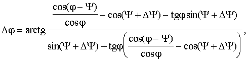
Поставленную задачу решают тем, что в известный способ регулирования четырехквадрантного преобразователя, при котором фазу вектора тока сети в каждом полупериоде питающего напряжения регулируют изменением модуляции входного напряжения коммутацией вентилей четырехквадрантного преобразователя, введены новые признаки: формируют массив значений М потребляемой мощности преобразователя, элементами которого являются допустимые значения фазы вектора тока сети и угла нагрузки, формируют массив прогнозных значений F фазы вектора тока сети, элементами которого являются текущее значение фазы вектора тока сети, текущее значение угла нагрузки и изменение угла нагрузки от текущего значения, которые, будучи реализованы, дают различимые комбинации управляющих воздействий, соответствующих допустимой потребляемой мощности преобразователя, причем прогнозное изменение фазы Δφ вектора тока сети в зависимости от текущего значения фазы вектора тока сети и текущего значения угла нагрузки при изменении угла нагрузки определяют по формулеThe problem is solved by the fact that in the known method of regulating a four-quadrant converter, in which the phase of the network current vector in each half-cycle of the supply voltage is controlled by changing the modulation of the input voltage by switching the valves of the four-quadrant converter, new features are introduced: an array of values M of the power consumption of the converter is formed, the elements of which are valid the values of the phase of the network current vector and the load angle, form an array of predicted values of the phase phase vector of the network current vector F whose elements are the current value of the phase of the current vector of the network, the current value of the load angle and the change in the angle of the load from the current value, which, when implemented, give distinguishable combinations of control actions corresponding to the allowable power consumption of the converter, and the predicted phase change Δφ of the network current vector from the current value of the phase of the current vector of the network and the current value of the load angle when changing the load angle is determined by the formula

где φ - текущее значение фазы вектора тока сети;where φ is the current phase value of the network current vector;
ψ - текущее значение угла нагрузки;ψ is the current value of the load angle;
Δψ - изменение угла нагрузки.Δψ is the change in the load angle.
В предлагаемом техническом решении, в отличие от прототипа, изменение угла сдвига фазы тока сети можно прогнозировать по изменению угла нагрузки. Это существенно разгрузит ресурсы системы регулирования, сократив время "прямого счета" обрабатываемой информации с датчиков сети и исключит работу преобразователя с недопустимыми параметрами регулирования, приводящими, в частности, к перегрузке тягового трансформатора.In the proposed technical solution, in contrast to the prototype, a change in the phase angle of the phase current of the network can be predicted by the change in the angle of the load. This will significantly unload the resources of the regulation system, reducing the time of "direct counting" of the processed information from the network sensors and excluding the operation of the converter with unacceptable regulation parameters, leading, in particular, to overloading the traction transformer.
Сказанное позволяет сделать вывод о причинно-следственной связи между совокупностью существенных признаков и достигаемым техническим результатом.The foregoing allows us to conclude that there is a causal relationship between the totality of essential features and the achieved technical result.
Сущность предлагаемого изобретения иллюстрируется векторной диаграммой четырехквадрантного преобразователя, из которой видно, что изменение угла нагрузки ψ вызывает изменение фазы φ вектора тока сети ![]()
![]()
С изменением (в данном случае увеличением) нагрузки происходит изменение вектора падения напряжения на индуктивности входной цепи ![]()
![]()
![]()
![]()

На фиг.4 приведена типовая зависимость мощности потребляемой преобразователем S (ось аппликат) от фазы φ вектора тока сети (ось абсцисс) и угла нагрузки ψ (ось ординат). Как видно из зависимости, существуют участки работы, определяемые углами φ и ψ, при которых возможно значительное превышение мощности потребляемой преобразователем, а следовательно и установленной рабочей мощности питающего трансформатора.Figure 4 shows a typical dependence of the power consumed by the transducer S (axis of applicate) on the phase φ of the network current vector (axis of abscissa) and the load angle ψ (ordinate axis). As can be seen from the dependence, there are sections of work determined by the angles φ and ψ, at which a significant excess of the power consumed by the converter, and therefore the installed operating power of the supply transformer, is possible.
Как показывает опыт проектирования подобных систем, ввиду ограниченности массо-габаритных показателей электроподвижного состава весьма сложно закладывать запасы по установленной мощности тягового трансформатора с целью снижения порога перегрузок, а аппаратное ограничение предельной мощности тягового трансформатора может ухудшить тяговые свойства электроподвижного состава. Это обстоятельство приводит к наличию недопустимых параметров работы трансформатора при питании четырехквадрантного преобразователя.As experience in the design of such systems shows, due to the limited weight and size parameters of electric rolling stock, it is very difficult to establish reserves for the installed power of the traction transformer in order to reduce the threshold of overloads, and hardware limiting the maximum power of the traction transformer can degrade the traction properties of the electric rolling stock. This circumstance leads to the presence of unacceptable parameters of the transformer when feeding a four-quadrant converter.
Фаза вектора тока сети и угол нагрузки являются элементами массива значений М мощности потребляемой преобразователем 
На приложенных к описанию чертежах показано:The drawings attached to the description show:
на фиг.1 - принципиальная схема четырехквадрантного преобразователя;figure 1 is a schematic diagram of a quadrant converter;
на фиг.2 - векторная диаграмма четырехквадрантного преобразователя;figure 2 is a vector diagram of a quadrant converter;
на фиг.3 - зависимость изменения фазы вектора тока сети от изменения угла нагрузки и текущего значения угла нагрузки;figure 3 - dependence of the phase change of the current vector of the network from changes in the load angle and the current value of the load angle;
на фиг.4 - зависимость мощности, потребляемой преобразователем от фазы вектора тока сети и угла нагрузки;figure 4 - dependence of the power consumed by the Converter from the phase of the current vector of the network and the load angle;
на фиг.5 - вариант структурной схемы, реализующей предложенный способ регулирования;figure 5 is a variant of the structural diagram that implements the proposed method of regulation;
на фиг.6 - алгоритм реализации предлагаемого способа регулирования;figure 6 - implementation algorithm of the proposed method of regulation;
Схема (фиг.5) представляет собой микропроцессорную систему регулирования четырехквадрантного преобразователя, в которой блоки 5, 7, 8 и 10 реализованы программно.The circuit (Fig. 5) is a microprocessor control system of a four-quadrant converter, in which
Преобразователь 1 управляется микропроцессорной системой автоматического регулирования, состоящей из процессора 2, оперативного запоминающего устройства (ОЗУ) 3, постоянного запоминающего устройства (ПЗУ) 4, блока синхронизации 5, аналого-цифрового преобразователя (АЦП) 6, блока прогнозирования фазы тока сети 7, блока определения потребляемой мощности преобразователя 8, блока драйверов 9 вентилей преобразователя 1, блока ввода-вывода временных интервалов 10, задатчика нагрузки 11. Входы-выходы процессора 2, ОЗУ 3, ПЗУ 4, выходы АЦП 6 и входы блока драйверов объединены шиной данных-адресов 12. Преобразователь 1 получает питание от однофазной сети переменного тока, напряжение которой поступает на вход блока синхронизации 5. Выход блока синхронизации соединен с шинами синхронизации процессора 2, ОЗУ 3, ПЗУ 4, АЦП 6, блока прогнозирования фазы тока сети 7. Текущее значение тока сети поступает на вход АЦП 6.The
Процессор 2, ОЗУ 3, ПЗУ 4 и АЦП 6 могут быть выполнены на базе микропроцессорного контроллера М167-1х (каталог продукции АО "КАСКОД" "Бортовая и промышленная электроника", 189625, С-Петербург, Павловск, Фильтровское шоссе, 3 (тел. (812) 466-5784, (812) 476-0795) с.66).
До реализации алгоритма рассматриваемого способа управления четырехквадрантного преобразователя формируют массив значений М потребляемой мощности преобразователя, элементами которого являются допустимые значения фазы вектора тока сети и угла нагрузки, формируют массив прогнозных значений F фазы вектора тока сети, элементами которого являются текущее значение фазы вектора тока сети, текущее значение угла нагрузки и изменение угла нагрузки от текущего значения, которые, будучи реализованы, дают различимые комбинации управляющих воздействий, соответствующих допустимой потребляемой мощности преобразователя.Prior to the implementation of the algorithm of the four-quadrant converter control method under consideration, an array of values M of the converter power consumption is formed, the elements of which are permissible phase values of the network current vector and load angle, an array of predicted values F of the phase of the network current vector is formed, whose elements are the current value of the phase of the network current vector the value of the load angle and the change in the load angle from the current value, which, when implemented, give distinguishable combinations of control The action corresponding to the allowable transmitter power consumption.
Массивы F и М формируют исходя из параметров регулирования и значений величин элементов схемы четырехквадрантного преобразователя. Сформированные массивы данных F и М помещают для хранения в память ПЗУ 4.Arrays F and M are formed based on the control parameters and the values of the elements of the four-quadrant converter circuit. The generated data arrays F and M are placed for storage in the
Способ реализуют следующим образом. При переходе питающего напряжения UN через нулевое значение на выходе блока синхронизации 5 появляется импульс, по которому производят начальную установку процессора 2, ОЗУ 3, ПЗУ 4, блока ввода-вывода временного интервала 10 и запуск АЦП 6. После этого микропроцессорная система автоматического регулирования четырехквадрантного преобразователя функционирует в соответствии с командами и константами, записанными в ПЗУ 4, причем в первом полупериоде питающего напряжения значения фазы вектора тока сети φ и значение угла нагрузки ψ задают равными номинальным.The method is implemented as follows. When the supply voltage U N passes through a zero value, an impulse appears at the output of the
В текущем полупериоде по приходу синхроимпульса (блок 13 (на фиг.6)) осуществляют ввод (блок 14) параметров и заданных допустимых рабочих значений преобразователя, ввод сформированного массива значений М потребляемой мощности преобразователя, элементами которого являются допустимые значения фазы вектора тока сети и угла нагрузки, ввод сформированного массива прогнозных значений F фазы вектора тока сети, элементами которого являются текущее значение фазы вектора тока сети, текущее значение угла нагрузки и изменение угла нагрузки от текущего значения, которые будучи реализованы, дают различимые комбинации управляющих воздействий, соответствующих допустимой потребляемой мощности преобразователя. При формировании массива F прогнозное изменение фазы Δφ вектора тока сети в зависимости от текущего значения фазы вектора тока сети и текущего значения угла нагрузки при изменении угла нагрузки определяют по формулеIn the current half-cycle upon arrival of the sync pulse (block 13 (in Fig. 6)), the parameters and specified permissible operating values of the converter are entered (block 14), the generated array of values M of the consumed power of the converter is entered, the elements of which are the permissible phase values of the network current vector and angle load, entering the generated array of forecast values F of the phase of the network current vector, whose elements are the current value of the phase of the network current vector, the current value of the load angle and the change in the load angle from the current of values which, when implemented, provide distinct combination of control actions corresponding to the allowable transmitter power consumption. When the array F is formed, the predicted phase change Δφ of the network current vector, depending on the current phase value of the network current vector and the current value of the load angle when the load angle is changed, is determined by the formula
где φ - текущее значение фазы вектора тока сети;where φ is the current phase value of the network current vector;
ψ - текущее значение угла нагрузки;ψ is the current value of the load angle;
Δψ - изменение угла нагрузки. Сигнал на изменение нагрузки (блок 15), полученный с задатчика нагрузки 11, подают в блок 16 где для значения заданного тока сети I'N определяют угол нагрузки ψЗ. В блоке 17 определяют изменение угла нагрузки Δψ от текущего значения ψ до заданного ψЗ. В блоке 18 выполняют прогнозирование фазы φЗ вектора тока сети при изменении нагрузки с исходного (текущего) состояния ψ, соответствующего сетевому току IN до заданного I'N по данным массива F. В блоке 19 прогнозное значение фазы вектора тока сети φз сравнивают с допустимым значением фазы вектора тока сети φдоп и в случае превышения φз над φдоп задают команду на снижение заданного значения потребляемого тока сети I'N (блок 20). Далее циклически определяют значение угла нагрузки, соответствующее сниженной нагрузке на величину ΔI. Величина изменения нагрузки ΔI за один цикл регулирования может принимать значения, равные, например, 0,005 от I'N. Нагрузку снижают до тех пор, пока угол нагрузки не будет соответствовать допустимой фазе тока сети из массива F. При соответствии прогнозной фазы вектора тока сети допустимой фазе тока сети из массива F прогнозируют мощность, потребляемую преобразователем (блок 21) по информации сформированной в массиве М, записанной и хранящейся в ПЗУ 4 системы регулирования. В случае превышения прогнозного значения мощности S из массива М (блок 22) при заданной нагрузке над значением допустимой мощности SДОП, снижают нагрузку (блок 20), а в случае ее соответствия допустимому значению формируют логику управления вентилями T1÷T4 четырехквадрантного преобразователя в блоке 10 для загрузки таймеров блока драйверов 9 (блок 23), обеспечивающих коммутацию преобразователя 1.Δψ is the change in the load angle. The signal to change the load (block 15), received from the
Отсчет ведут от синхроимпульса в начале каждого полупериода питающего напряжения (блок 13).The reference is from the clock at the beginning of each half-cycle of the supply voltage (block 13).
Таким образом, предложенный способ регулирования четырехквадрантного преобразователя позволяет заранее, до достижения регулятором требуемой величины нагрузки, исключать недопустимые комбинации параметров регулирования, приводящие к перегрузке тягового трансформатора, сократить количество функциональных преобразований при реализации требуемых параметров с целью снижения времени "прямого счета" системой регулирования, однозначно определять логико-математическим путем изменение фазы вектора тока сети при изменении нагрузки.Thus, the proposed method of regulating a four-quadrant converter allows in advance, before the regulator reaches the required load, to exclude unacceptable combinations of regulation parameters leading to overload of the traction transformer, to reduce the number of functional transformations when implementing the required parameters in order to reduce the time of direct counting by the regulation system, unambiguously determine the logical-mathematical way of changing the phase of the network current vector when the load changes.
Примером конкретной реализации предложенного способа прогнозирующего векторного управления четырехквадрантного преобразователя является физическая модель четырехквадрантного преобразователя испытательного стенда ОАО "ВЭлНИИ". В качестве нагрузки преобразователя использовался трехфазный инвертор напряжения, питающий индукторный двигатель НТИ-350.An example of a specific implementation of the proposed method for predictive vector control of a four-quadrant converter is a physical model of a four-quadrant converter of the test bench of VELNII OJSC. As the load of the converter, a three-phase voltage inverter was used, which feeds the NTI-350 induction motor.
Коэффициент мощности четырехквадрантного преобразователя составил 0,9991 и оказался инвариантен к нагрузке. Значение выходного напряжения преобразователя поддерживалось на заданном уровне (1350 В) при изменении мощности нагрузки в диапазоне от 10 до 350 кВт. При этом значительно (в 2,7 раза) сократился объем управляющей программы системы регулирования.The power factor of the four-quadrant converter was 0.9991 and was load-invariant. The value of the converter output voltage was maintained at a given level (1350 V) when the load power changed in the range from 10 to 350 kW. At the same time, the volume of the control program of the regulatory system decreased significantly (2.7 times).
Настоящее изобретение, основанное на прогнозном определении фазы вектора тока сети при изменении нагрузки, позволяет регулировать заданную фазу потребляемого тока сети во всем диапазоне работы и исключать недопустимые комбинации параметров регулирования, способных ухудшить энергетические показатели работы четырехквадрантного преобразователя.The present invention, based on the predictive determination of the phase of the network current vector when the load changes, allows you to adjust the specified phase of the consumed network current in the entire operating range and to eliminate unacceptable combinations of control parameters that can degrade the energy performance of the quadrant converter.
Предлагаемое изобретение может найти применение в системах тягового привода электроподвижного состава переменного тока, где в качестве входных преобразователей используются четырехквадрантные преобразователи. Способ применим также и при параллельной работе четырехквадрантных преобразователей с любым типом модуляции входного напряжения.The present invention can find application in traction drive systems of electric rolling stock of alternating current, where four-quadrant converters are used as input converters. The method is also applicable for parallel operation of quadrant converters with any type of input voltage modulation.
Claims (1)
Priority Applications (1)
| Application Number | Priority Date | Filing Date | Title |
|---|---|---|---|
| RU2004128038/09A RU2284635C2 (en) | 2004-09-20 | 2004-09-20 | Method for predicting vector adjustment of four-quadrant transformer |
Applications Claiming Priority (1)
| Application Number | Priority Date | Filing Date | Title |
|---|---|---|---|
| RU2004128038/09A RU2284635C2 (en) | 2004-09-20 | 2004-09-20 | Method for predicting vector adjustment of four-quadrant transformer |
Publications (2)
| Publication Number | Publication Date |
|---|---|
| RU2004128038A RU2004128038A (en) | 2006-03-10 |
| RU2284635C2 true RU2284635C2 (en) | 2006-09-27 |
Family
ID=36115599
Family Applications (1)
| Application Number | Title | Priority Date | Filing Date |
|---|---|---|---|
| RU2004128038/09A RU2284635C2 (en) | 2004-09-20 | 2004-09-20 | Method for predicting vector adjustment of four-quadrant transformer |
Country Status (1)
| Country | Link |
|---|---|
| RU (1) | RU2284635C2 (en) |
-
2004
- 2004-09-20 RU RU2004128038/09A patent/RU2284635C2/en not_active IP Right Cessation
Also Published As
| Publication number | Publication date |
|---|---|
| RU2004128038A (en) | 2006-03-10 |
Similar Documents
| Publication | Publication Date | Title |
|---|---|---|
| US7746039B2 (en) | Method for controlled application of a stator current set point value and of a torque set point value for a converter-fed rotating-field machine | |
| CN103534932A (en) | System and method for fast start-up of an induction motor | |
| US4581568A (en) | Method and apparatus for automatically setting the demand phase lag input to an induction-motor power factor controller | |
| CN108900115B (en) | Self-adaptive current control method for pumped storage static frequency converter | |
| JPH05316792A (en) | Controller and controlling method for induction motor | |
| US6737827B2 (en) | Method and apparatus to control input to AC induction motors | |
| JP6093283B2 (en) | Synchronizing device | |
| US20120275200A1 (en) | Resonant Circuit Inverter With Controllable Operating Point | |
| RU2284635C2 (en) | Method for predicting vector adjustment of four-quadrant transformer | |
| RU2362264C1 (en) | Method of controlling alternating current drive | |
| CN101986798B (en) | Method and system for braking an AC motor | |
| Ladygin et al. | Developing dead-beat control in a valve electric drive | |
| Okumus et al. | Direct torque control of induction machine drives using adaptive hysteresis band for constant switching frequency | |
| KR101284929B1 (en) | Apparatus and method for controlling power factor correction in power supply | |
| RU2327276C1 (en) | Method of control of tetrasquare converter with computation of switching phases and microprocessor device to implement method | |
| CN112838802A (en) | Method and apparatus for controlling operation of rotating electric machine | |
| RU2315415C2 (en) | Method for control of tetragonal converter | |
| Jin et al. | Simulation analysis of control system in an innovative magnetically-saturated controllable reactor | |
| US5307258A (en) | Process for converting a first AC signal into a second AC signal and a converter for performing the process | |
| Ramirez et al. | Enhanced control of the torque ripple in a PMSM drive with variable switching frequency | |
| EP3987635A1 (en) | Circuit and method for bus voltage variation in power converters | |
| CN203466768U (en) | Phase advancer capable of automatically regulating voltage | |
| RU2760393C2 (en) | Method for controlling autonomous asynchronous generator | |
| JPH04351492A (en) | Controller for induction motor | |
| EP4340202A1 (en) | Electronic apparatus, switching system, and control method |
Legal Events
| Date | Code | Title | Description |
|---|---|---|---|
| MM4A | The patent is invalid due to non-payment of fees |
Effective date: 20060921 |