RU2284558C2 - Progressive lens with gradual growth of focal power - Google Patents
Progressive lens with gradual growth of focal power Download PDFInfo
- Publication number
- RU2284558C2 RU2284558C2 RU2003129985/28A RU2003129985A RU2284558C2 RU 2284558 C2 RU2284558 C2 RU 2284558C2 RU 2003129985/28 A RU2003129985/28 A RU 2003129985/28A RU 2003129985 A RU2003129985 A RU 2003129985A RU 2284558 C2 RU2284558 C2 RU 2284558C2
- Authority
- RU
- Russia
- Prior art keywords
- progressive
- lens
- regressive
- combined
- astigmatism
- Prior art date
Links
Images


Classifications
-
- G—PHYSICS
- G02—OPTICS
- G02C—SPECTACLES; SUNGLASSES OR GOGGLES INSOFAR AS THEY HAVE THE SAME FEATURES AS SPECTACLES; CONTACT LENSES
- G02C7/00—Optical parts
- G02C7/02—Lenses; Lens systems ; Methods of designing lenses
- G02C7/06—Lenses; Lens systems ; Methods of designing lenses bifocal; multifocal ; progressive
- G02C7/061—Spectacle lenses with progressively varying focal power
- G02C7/063—Shape of the progressive surface
-
- G—PHYSICS
- G02—OPTICS
- G02C—SPECTACLES; SUNGLASSES OR GOGGLES INSOFAR AS THEY HAVE THE SAME FEATURES AS SPECTACLES; CONTACT LENSES
- G02C7/00—Optical parts
- G02C7/02—Lenses; Lens systems ; Methods of designing lenses
- G02C7/06—Lenses; Lens systems ; Methods of designing lenses bifocal; multifocal ; progressive
- G02C7/061—Spectacle lenses with progressively varying focal power
Abstract
Description
Область техникиTechnical field
Настоящее изобретение относится к мультифокальным офтальмическим линзам. В частности, предложены конструкции прогрессивных линз с постепенным увеличением оптической силы, в которых нежелательный астигматизм уменьшен по сравнению с традиционными прогрессивными линзами.The present invention relates to multifocal ophthalmic lenses. In particular, progressive lens designs have been proposed with a gradual increase in optical power, in which unwanted astigmatism is reduced compared to traditional progressive lenses.
Описание известного уровня техникиDescription of the prior art
Использование офтальмических линз для коррекции аметропии хорошо известно. Например, для лечения пресбиопии используются мультифокальные линзы, такие как прогрессивные линзы с постепенным увеличением оптической силы (ПЛПУОС). Прогрессивная поверхность ПЛПУОС обеспечивает дальнее, промежуточное и ближнее зрение с постепенной непрерывной прогрессией диоптрийности, возрастающей по вертикали от дальнего к ближнему фокусу линзы или сверху вниз.The use of ophthalmic lenses for the correction of ametropia is well known. For example, multifocal lenses such as progressive lenses with a gradual increase in optical power (PLPUOS) are used to treat presbyopia. The progressive surface of the PLPUOS provides far, intermediate and near vision with a gradual continuous progression of diopter, increasing vertically from the far to the near focus of the lens or from top to bottom.
ПЛПУОС благоприятны для пользователей, потому что они не имеют видимых ступеней между зонами различной диоптрийности, присущих другим мультифокальным линзам, таким как бифокалы и трифокалы. Однако характерным недостатком ПЛПУОС является наличие нежелательного астигматизма или астигматизма, вызванного одной или более поверхностями линзы. В ПЛПУОС жесткой конструкции нежелательный астигматизм расположен по границе между каналом линзы и зоной ближнего зрения. В ПЛПУОС мягкой конструкции нежелательный астигматизм простирается в зону дальнего зрения. Обычно в обоих видах конструкции нежелательный астигматизм линзы в ее центре или вблизи него достигает максимума, который приблизительно соответствует аддидации (прибавленной диоптрийности) ближнего зрения данной линзы.PLPUOS is favorable for users because they do not have visible steps between zones of different diopters inherent in other multifocal lenses, such as bifocal and trifocal. However, a characteristic disadvantage of PLPOS is the presence of unwanted astigmatism or astigmatism caused by one or more lens surfaces. In a rigid-structure PLPUOS, unwanted astigmatism is located along the boundary between the lens channel and the near vision zone. In a soft-built soft shelving system, unwanted astigmatism extends into the far vision zone. Usually, in both types of construction, the unwanted astigmatism of the lens in its center or near it reaches a maximum that approximately corresponds to the addition (added diopter) of the near vision of this lens.
Известно много конструкций ПЛПУОС, в которых проблема снижения нежелательного астигматизма решается с переменным успехом. Одна такая конструкция описана в патенте США №5726734, в котором использована комбинированная конструкция, которая вычисляется посредством объединения значений изгиба твердой и мягкой конструкции ПЛПУОС. В конструкции, описанной в данном патенте, максимальный локализованный нежелательный астигматизм комбинированной конструкции равен сумме вкладов областей жесткой и мягкой конструкций с максимальным нежелательным астигматизмом. Это накладывает ограничение на уменьшение максимального локализованного нежелательного астигматизма, которое может быть реализовано данной конструкцией линзы. Следовательно, существует потребность в конструкции, которая бы позволила еще больше уменьшить максимальный локализованный нежелательный астигматизм по сравнению с известными конструкциями линз.There are many designs of PLPUOS, in which the problem of reducing unwanted astigmatism is solved with varying success. One such design is described in US Pat. No. 5,726,734, which uses a combined design, which is calculated by combining the flexural values of the hard and soft design of PLPUOS. In the design described in this patent, the maximum localized unwanted astigmatism of the combined structure is equal to the sum of the contributions of the hard and soft regions with the maximum undesired astigmatism. This imposes a restriction on reducing the maximum localized unwanted astigmatism that can be implemented by this lens design. Therefore, there is a need for a design that would further reduce the maximum localized unwanted astigmatism compared to known lens designs.
Сущность изобретенияSUMMARY OF THE INVENTION
Все указанные недостатки известного уровня техники устраняются заявленным изобретением. Согласно первому аспекту изобретения предусмотрена прогрессивная линза с постепенным увеличением оптической силы, содержит, по меньшей мере, одну поверхность, комбинированную из прогрессивной поверхности и регрессивной поверхности.All these disadvantages of the prior art are eliminated by the claimed invention. According to a first aspect of the invention, there is provided a progressive lens with a gradual increase in optical power, comprising at least one surface combined from a progressive surface and a regressive surface.
Кроме того, в указанной линзе комбинированная поверхность имеет максимальный локализованный нежелательный астигматизм, который меньше, чем на около 0,125 диоптрии, чем сумма абсолютных значений максимального локализованного астигматизма каждой из прогрессивной и регрессивной поверхностей.In addition, in the specified lens, the combined surface has a maximum localized unwanted astigmatism, which is less than about 0.125 diopters than the sum of the absolute values of the maximum localized astigmatism of each of the progressive and regressive surfaces.
При этом линза дополнительно содержит вторую прогрессивную поверхность с постепенным увеличением оптической силы. Указанная линза дополнительно содержит вторую поверхность, являющуюся регрессивной поверхностью.Moreover, the lens further comprises a second progressive surface with a gradual increase in optical power. The specified lens further comprises a second surface, which is a regressive surface.
Кроме того, линза имеет нормированную дисторсию линзы меньше, чем около 300 мм2.In addition, the lens has a normalized lens distortion of less than about 300 mm 2 .
Согласно второму аспекту изобретения предусмотрена прогрессивная поверхность с постепенным увеличением оптической силы, содержащая комбинированную поверхность из прогрессивной поверхности и регрессивной поверхности, причем комбинированная поверхность имеет максимальный локализованный нежелательный астигматизм, который меньше, чем на около 0,125 диоптрии, чем сумма абсолютных значений максимального локализованного астигматизма каждой из прогрессивной и регрессивной поверхностей.According to a second aspect of the invention, there is provided a progressive surface with a gradual increase in optical power, comprising a combined surface of a progressive surface and a regressive surface, the combined surface having a maximum localized unwanted astigmatism that is less than about 0.125 diopters than the sum of the absolute values of the maximum localized astigmatism of each of progressive and regressive surfaces.
Согласно другому аспекту изобретения предусмотрен способ формирования конструкции прогрессивной поверхности с постепенным увеличением оптической силы, заключающийся в том, что (а) формируют конструкцию прогрессивной поверхности, имеющей, по меньшей мере, одну область нежелательного астигматизма, (b) формируют конструкцию регрессивной поверхности, имеющей, по меньшей мере, одну вторую область нежелательного астигматизма, и (с) объединяют конструкции прогрессивной и регрессивной поверхностей для получения конструкции комбинированной прогрессивной поверхности, причем упомянутые по меньшей мере одна первая и вторая области нежелательного астигматизма по существу совмещены.According to another aspect of the invention, there is provided a method of forming a progressive surface structure with a gradual increase in optical power, namely (a) forming a progressive surface structure having at least one region of unwanted astigmatism, (b) forming a regressive surface structure having, at least one second region of unwanted astigmatism, and (c) combine the design of the progressive and regressive surfaces to obtain a combined rogressivnoy surface, said at least one first and second areas of unwanted astigmatism substantially aligned.
При этом каждая из конструкций прогрессивной и регрессивной поверхностей является одной из жесткой конструкции, мягкой конструкции или их комбинации.Moreover, each of the structures of progressive and regressive surfaces is one of a rigid structure, soft structure, or a combination thereof.
Кроме того, согласно указанному способу каждая из конструкций прогрессивной и регрессивной поверхностей является жесткой конструкцией.In addition, according to the specified method, each of the structures of the progressive and regressive surfaces is a rigid structure.
При этом каждая из конструкций прогрессивной и регрессивной поверхностей является мягкой конструкцией.Moreover, each of the designs of progressive and regressive surfaces is a soft design.
Согласно заявленному способу поверхность, сформированная из конструкции комбинированной поверхности, имеет максимальный локализованный нежелательный астигматизм, который меньше, чем на около 0,125 диоптрии, чем сумма абсолютных значений максимального локализованного нежелательного астигматизма каждой из прогрессивной и регрессивной поверхностей.According to the claimed method, a surface formed from the construction of a combined surface has a maximum localized unwanted astigmatism, which is less than about 0.125 diopters than the sum of the absolute values of the maximum localized unwanted astigmatism of each of the progressive and regressive surfaces.
Кроме того, конструкция комбинированной поверхности содержит более чем одну область максимального локализованного нежелательного астигматизма на каждой стороне канала комбинированной поверхности.In addition, the design of the combined surface contains more than one region of maximum localized unwanted astigmatism on each side of the channel of the combined surface.
При этом конструкции прогрессивной и регрессивной поверхностей представлены в виде отклонений изгиба от базовой кривизны. При этом базовая кривизна является вогнутой кривизной или выпуклой кривизной.Moreover, the designs of progressive and regressive surfaces are presented in the form of deviations of the bend from the base curvature. In this case, the base curvature is concave curvature or convex curvature.
Кроме того, согласно указанному способу этап (с) осуществляют посредством сложения значений изгиба конструкций прогрессивной поверхности и регрессивной поверхности согласно следующему уравнению:In addition, according to the specified method, step (c) is carried out by adding the bending values of the structures of the progressive surface and the regressive surface according to the following equation:
![]()
![]()
где Z - отклонение значения изгиба комбинированной поверхности от базовой кривизны в точке (x, y), Zi - отклонение изгиба для i-й поверхности, подлежащей объединению в точке (x, y), и ai - коэффициенты.where Z is the deviation of the bending value of the combined surface from the base curvature at the point (x, y), Z i is the deviation of the bend for the i-th surface to be combined at the point (x, y), and a i are the coefficients.
Краткое описание чертежейBrief Description of the Drawings
Фиг.1 иллюстрирует область дисторсии прогрессивной линзы,Figure 1 illustrates the region of distortion of a progressive lens,
Фиг.2 изображает контур цилиндра прогрессивной поверхности, использованной в линзе по примеру 1,Figure 2 depicts the cylinder contour of the progressive surface used in the lens of example 1,
Фиг.2b - контур диоптрийности прогрессивной поверхности, использованной в линзе по примеру 1,Fig.2b - diopter contour of the progressive surface used in the lens of example 1,
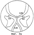
Фиг.3а - карту цилиндра регрессивной поверхности, использованной в линзе по примеру 1,Figa - cylinder map of the regression surface used in the lens of example 1,
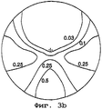
Фиг.3b - карту диоптрийности регрессивной поверхности, использованной в линзе по примеру 1,Fig.3b is a dioptric map of the regression surface used in the lens of example 1,
Фиг.4а - контур цилиндра комбинированной поверхности по примеру 1,Figa - cylinder contour of the combined surface according to example 1,
Фиг.4b - контур диоптрийности комбинированной поверхности по примеру 1,Fig.4b - dioptric contour of the combined surface according to example 1,
Фиг.5 - контур цилиндра вогнутой прогрессивной поверхности по примеру 2,Figure 5 - contour of the cylinder concave progressive surface according to example 2,
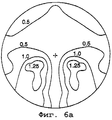
Фиг.6а - контур цилиндра линзы по примеру 2,Figa - outline of the cylinder of the lens according to example 2,
Фиг.6b - контур диоптрийности линзы по примеру 2,Fig.6b - dioptric contour of the lens according to example 2,
Фиг.7а - контур цилиндра традиционной линзы,Figa - cylinder outline of a traditional lens,
Фиг.7b - контур диоптрийности обычной линзы,Fig.7b - dioptric contour of a conventional lens,
Фиг.8 - контур цилиндра вогнутой прогрессивной прибавляющей поверхности линзы по примеру 3,Fig. 8 is a cylinder outline of a concave progressive adding lens surface of Example 3,
Фиг.9а - контур цилиндра линзы по примеру 3,Figa - outline of the cylinder of the lens according to example 3,
Фиг.9b - контур диоптрийности линзы по примеру 3.Fig. 9b is a dioptric contour of the lens of Example 3.
Описание изобретения и предпочтительных вариантов его осуществленияDescription of the invention and preferred embodiments thereof
В настоящем изобретении комбинированная поверхность образована посредством объединения конструкций прогрессивной и регрессивной поверхностей. Было обнаружено, что прогрессивные линзы с уменьшенным нежелательным астигматизмом можно сконструировать посредством объединения прогрессивной прибавляющей и регрессивной поверхностей в одну комбинированную поверхность.In the present invention, a combined surface is formed by combining designs of progressive and regressive surfaces. It has been found that progressive lenses with reduced unwanted astigmatism can be constructed by combining progressive adding and regressing surfaces into one combined surface.
Согласно одному варианту осуществления изобретения предложен способ формирования конструкции прогрессивной поверхности с постепенным увеличением оптической силы, состоящий из или состоящий по существу из (а) формирования конструкции прогрессивной поверхности, имеющей по меньшей мере одну первую область нежелательного астигматизма, (b) формирования конструкции регрессивной поверхности, имеющей по меньшей мере одну вторую область нежелательного астигматизма, и (с) объединения конструкций прогрессивной поверхности и регрессивной поверхности для формирования конструкции комбинированной прогрессивной поверхности, в которой упомянутые по меньшей мере одна первая и вторая области нежелательного астигматизма совмещены. Согласно другому варианту осуществления изобретения предложена прогрессивная линза с постепенным увеличением оптической силы, состоящая из или состоящая по существу из поверхности с конструкцией комбинированной поверхности, полученной предложенным способом.According to one embodiment of the invention, there is provided a method of forming a progressive surface structure with a gradual increase in optical power, consisting of or consisting essentially of (a) forming a progressive surface structure having at least one first region of unwanted astigmatism, (b) forming a regressive surface structure, having at least one second region of unwanted astigmatism, and (c) combining progressive surface and regressive structures rhnosti to form a composite progressive surface design, wherein the at least one first and second areas of unwanted astigmatism are aligned. According to another embodiment of the invention, there is provided a progressive lens with a gradual increase in optical power, consisting of or consisting essentially of a surface with a combined surface structure obtained by the proposed method.
Под "линзой" или "линзами" подразумевается любая офтальмическая линза, включая, без ограничения перечисленным, очковые линзы, контактные линзы, искусственный хрусталик и т.п. Предпочтительно предложенная линза является очковой линзой.By “lens” or “lenses” is meant any ophthalmic lens, including but not limited to eyeglass lenses, contact lenses, an artificial lens, and the like. Preferably, the proposed lens is a spectacle lens.
Под "прогрессивной поверхностью с постепенным увеличением оптической силы" подразумевается непрерывная асферическая поверхность, имеющая зоны дальней видимости и ближней видимости или зону видимости и зону возрастающей диоптрийности, соединяющую зоны дальней и ближней видимости. Специалистам будет понятно, что если прогрессивная поверхность является выпуклой поверхностью линзы, то кривизна зоны дальней видимости будет меньше, чем кривизна зоны ближней видимости, а если прогрессивная поверхность является вогнутой поверхностью линзы, то кривизна зоны дальней видимости будет больше кривизны зоны ближней видимости.By "progressive surface with a gradual increase in optical power" is meant a continuous aspherical surface having a zone of far visibility and near vision or a zone of visibility and a zone of increasing diopter, connecting the zone of far and near visibility. It will be clear to those skilled in the art that if the progressive surface is a convex surface of the lens, then the curvature of the far field will be less than the curvature of the near field, and if the progressive surface is a concave surface of the lens, then the curvature of the far field will be greater than the curvature of the near field.
Под "областью нежелательного астигматизма" подразумевается область на поверхности линзы, имеющая около 0,25 диоптрии или больше нежелательного астигматизма.By "area of unwanted astigmatism" is meant a region on the surface of the lens having about 0.25 diopters or more of unwanted astigmatism.
Под "регрессивной поверхностью" подразумевается непрерывная асферическая поверхность, имеющая зоны дальней и ближней видимости, или видимости, и зону уменьшающейся диоптрийности, соединяющую зоны дальней и ближней видимости. Если регрессивная поверхность является выпуклой поверхностью линзы, то кривизна зоны дальней видимости будет больше кривизны зоны ближней видимости, а если регрессивная поверхность является вогнутой поверхностью линзы, то кривизна зоны дальней видимости будет меньше кривизны зоны ближней видимости.By "regressive surface" is meant a continuous aspherical surface having zones of near and far visibility, or visibility, and a zone of diminishing diopter, connecting the zones of far and near visibility. If the regressive surface is the convex surface of the lens, then the curvature of the far field will be greater than the curvature of the near field, and if the regressive surface is a concave surface of the lens, then the curvature of the far field will be less than the curvature of the near field.
Понятие "совмещенные" в отношении областей нежелательного астигматизма означает, что области нежелательного астигматизма располагаются таким образом, что имеется их частичное или по существу полное наложение или совпадение, когда эти поверхности объединены для образования комбинированной поверхности.The term “aligned” with respect to areas of unwanted astigmatism means that areas of unwanted astigmatism are positioned in such a way that there is partial or substantially complete overlap or coincidence when these surfaces are combined to form a combined surface.
Для построения и оптимизации прогрессивной конструкции обычно используется ряд оптических параметров. Эти параметры включают в себя области нежелательного астигматизма, области максимального локализованного нежелательного астигматизма, длину и ширину канала, ширину зоны дальней видимости и зоны чтения, ширину диоптрийности чтения и нормированное искажение линзы. Под нормированным искажением линзы следует понимать объединенный нежелательный астигматизм линзы ниже оптического центра, основной опорной точки, деленный на аддидацию линзы. Со ссылкой на фиг.1 для прогрессивных линз с постепенным увеличением оптической силы нормированное искажение линзы DL можно вычислить из уравнения:A number of optical parameters are usually used to construct and optimize a progressive design. These parameters include areas of unwanted astigmatism, areas of maximum localized unwanted astigmatism, the length and width of the channel, the width of the far viewing zone and reading zone, the width of the diopter reading and normalized distortion of the lens. Under normalized lens distortion should be understood combined unwanted astigmatism of the lens below the optical center, the main reference point divided by the addition of the lens. With reference to figure 1 for progressive lenses with a gradual increase in optical power, the normalized distortion of the lens D L can be calculated from the equation:
![]()
![]()
где AL - площадь линзы; NW - ширина зоны ближней видимости; МA - максимальный локализованный нежелательный астигматизм (самый высокий измеримый уровень астигматизма в области нежелательного астигматизма на поверхности линзы) и Ар - диоптрийность линзы при y=-20 мм под основной опорной точкой. AI - площадь промежуточной зоны, в которой нежелательный астигматизм меньше, чем 0,5 диоптрии, и вычисляется из уравнения:where A L is the area of the lens; N W - the width of the zone of near visibility; M A is the maximum localized unwanted astigmatism (the highest measurable level of astigmatism in the area of unwanted astigmatism on the surface of the lens) and A p is the dioptricity of the lens at y = -20 mm below the main reference point. A I - the area of the intermediate zone in which unwanted astigmatism is less than 0.5 diopters, and is calculated from the equation:
![]()
![]()
где IW - ширина промежуточной зоны, в которой нежелательный астигматизм меньше, чем 0,5 диоптрии; DW и NW - ширина зон дальней (при y=0) и ближней (при y=-20 мм) видимости соответственно, в которых нежелательный астигматизм меньше, чем около 0,5 диоптрии, и IL - длина вдоль центра канала между начальной точкой призмы и самой узкой шириной в промежуточной зоне.where I W is the width of the intermediate zone in which unwanted astigmatism is less than 0.5 diopters; D W and N W are the widths of the far (at y = 0) and near (at y = -20 mm) zones of visibility, respectively, in which undesirable astigmatism is less than about 0.5 diopters, and I L is the length along the channel center between the starting point of the prism and the narrowest width in the intermediate zone.
Для целей уравнения II ширина зоны ближней видимости и промежуточной зоны не являются синонимами ширины зоны чтения и канала. Напротив, тогда как ширина зоны чтения и ширина канала определяются на основании клинически релевантного порога хорошего зрения, ширина зоны ближней видимости и ширина промежуточной зоны по уравнению II основаны на астигматическом пороге 0,5 диоптрии.For the purposes of equation II, the width of the near vision zone and the intermediate zone are not synonymous with the width of the reading zone and the channel. On the contrary, while the width of the reading zone and the width of the channel are determined on the basis of the clinically relevant threshold of good vision, the width of the near vision zone and the width of the intermediate zone according to equation II are based on the astigmatic threshold of 0.5 diopters.
В предложенных линзах нормированное искажение линзы значительно ниже, чем в известных прогрессивных линзах с постепенным увеличением оптической силы. Так, в предпочтительном варианте осуществления изобретения предложена прогрессивная линза с постепенным увеличением оптической силы, состоящая из или состоящая по существу из, по меньшей мере одной, прогрессивной поверхности с постепенным увеличением оптической силы, имеющей нормированную дисторсию линзы меньше, чем около 300.In the proposed lenses, the normalized distortion of the lens is significantly lower than in the known progressive lenses with a gradual increase in optical power. Thus, in a preferred embodiment of the invention, there is provided a progressive lens with a gradual increase in optical power, consisting of or consisting essentially of at least one progressive surface with a gradual increase in optical power, having a normalized lens distortion of less than about 300.
В предложенных линзах аддидация, или величина различия в диоптрийности между зонами дальней и ближней видимости, в конструкции прогрессивной поверхности является положительной величиной, а в конструкции регрессивной поверхности - отрицательной величиной. Следовательно, поскольку аддидация комбинированной поверхности есть сумма аддидаций конструкций прогрессивной и регрессивной поверхности, конструкция регрессивной поверхности осуществляет вычитание аддидации из конструкции прогрессивной поверхности.In the proposed lenses, the addition, or the difference in diopter between the zones of far and near visibility, in the design of a progressive surface is a positive value, and in the design of a regressive surface it is a negative value. Therefore, since the addition of a combined surface is the sum of the additions of the structures of the progressive and regressive surfaces, the design of the regressive surface subtracts the additions from the design of the progressive surface.
Известно, что прогрессивная поверхность с постепенным увеличением оптической силы создает нежелательный астигматизм в определенных областях поверхности. Нежелательный астигматизм какой-то области можно рассматривать как векторную величину, величина и ось ориентации которой зависит частично от местоположения астигматизма на поверхности. Регрессивная поверхность также имеет области нежелательного астигматизма, величина и ось которого определяются теми же факторами, которые являются определяющими для астигматизма прогрессивной поверхности. Однако ось астигматизма регрессивной поверхности типично расположена ортогонально оси астигматизма прогрессивной поверхности. Альтернативно, величину астигматизма регрессивной поверхности можно рассматривать как противоположную по знаку относительно астигматизма прогрессивной поверхности на той же самой оси.It is known that a progressive surface with a gradual increase in optical power creates undesirable astigmatism in certain areas of the surface. Unwanted astigmatism of any region can be considered as a vector quantity, the magnitude and orientation axis of which depends in part on the location of astigmatism on the surface. The regressive surface also has areas of unwanted astigmatism, the magnitude and axis of which are determined by the same factors that are decisive for astigmatism of the progressive surface. However, the astigmatism axis of the regressive surface is typically located orthogonal to the astigmatism axis of the progressive surface. Alternatively, the magnitude of the astigmatism of the regressive surface can be considered as opposite in sign with respect to the astigmatism of the progressive surface on the same axis.
Следовательно, объединение конструкции прогрессивной поверхности с областью нежелательного астигматизма с конструкцией регрессивной поверхности с соответственно расположенной областью нежелательного астигматизма уменьшает общий нежелательный астигматизм этой области при объединении этих двух конструкций для образования комбинированной поверхности линзы. Это объясняется тем, что нежелательный астигматизм линзы на данном участке будет векторной суммой нежелательных астигматизмов конструкций прогрессивной и регрессивной поверхности. Так как величины астигматизмов конструкций прогрессивной с постепенным увеличением оптической силы и регрессивной поверхности имеют противоположные знаки, достигается уменьшение общего нежелательного астигматизма данной комбинированной поверхности. Хотя ось ориентации нежелательного астигматизма конструкции регрессивной поверхности не должна быть такой же, как на соответствующем участке конструкции прогрессивной поверхности, для обеспечения максимального уменьшения нежелательного астигматизма предпочтительно, чтобы эти оси были по существу одинаковыми.Therefore, combining the progressive surface structure with the region of unwanted astigmatism with the regression surface structure with the correspondingly located region of unwanted astigmatism reduces the overall unwanted astigmatism of this region when combining these two structures to form a combined lens surface. This is because the unwanted astigmatism of the lens in this area will be the vector sum of the unwanted astigmatisms of the structures of the progressive and regressive surfaces. Since the magnitude of the astigmatism of progressive structures with a gradual increase in optical power and regressive surface have opposite signs, a decrease in the total undesirable astigmatism of this combined surface is achieved. Although the orientation axis of the unwanted astigmatism of the regressive surface structure does not have to be the same as that of the corresponding portion of the progressive surface structure, it is preferable that these axes be substantially the same to minimize the unwanted astigmatism.
Для обеспечения уменьшения нежелательного астигматизма в комбинированной поверхности по меньшей мере одна область астигматизма в конструкции прогрессивной поверхности должна быть совмещена с одной областью астигматизма конструкции регрессивной поверхности. Предпочтительно, чтобы области максимального локализованного нежелательного астигматизма или области наивысшего измеримого нежелательного астигматизма каждой из конструкций поверхности были совмещены. Более предпочтительно, чтобы все области нежелательного астигматизма конструкции одной поверхности были совмещены с областями нежелательного астигматизма конструкции другой поверхности.In order to reduce unwanted astigmatism in the combined surface, at least one astigmatism region in the progressive surface structure must be combined with one astigmatism region of the regressive surface structure. Preferably, the areas of maximum localized unwanted astigmatism or areas of the highest measurable unwanted astigmatism of each of the surface structures are aligned. More preferably, all areas of unwanted astigmatism of a structure of one surface are aligned with areas of unwanted astigmatism of a structure of another surface.
В другом варианте изобретения совмещены зоны дальней видимости и ближней видимости поверхностей, а также каналы. При таком совмещении поверхностей одна или более областей нежелательного астигматизма конструкции прогрессивной поверхности будут перекрываться с одной или более такими областями конструкции регрессивной поверхности. В следующем варианте изобретения предложена поверхность линзы, состоящая из или состоящая по существу из одной или более конструкций прогрессивной поверхности с постепенным увеличением оптической силы и одной или более конструкций регрессивной поверхности, причем зоны дальней видимости, зоны ближней видимости и каналы конструкций прогрессивной и регрессивной поверхностей по существу совмещены.In another embodiment of the invention, the areas of far visibility and near visibility of surfaces, as well as channels, are combined. With such a combination of surfaces, one or more regions of unwanted astigmatism of the progressive surface structure will overlap with one or more such regions of the regressive surface structure. In a further embodiment of the invention, there is provided a lens surface consisting of or consisting essentially of one or more progressive surface structures with a gradual increase in optical power and one or more regressive surface structures, the long-range zones, near-vision zones and channels of the progressive and regressive surface structures along creatures combined.
В предложенных линзах комбинированная поверхность может находиться на выпуклой, вогнутой или на обеих поверхностях линзы или располагаться в слоях между этими поверхностями. В предпочтительном варианте осуществления комбинированная поверхность образует выпуклую поверхность линзы. В комбинированной поверхности можно использовать одну или более конструкций прогрессивной с постепенным увеличением оптической силы и регрессивной поверхности, но предпочтительно используется только одна конструкция каждой поверхности. В вариантах, в которых комбинированная поверхность находится в промежуточном слое между вогнутой и выпуклой поверхностями, предпочтительно использовать для комбинированной поверхности материалы с показателем преломления, который отличается, по меньшей мере, приблизительно на 0,01, предпочтительно, по меньшей мере, на 0,05, более предпочтительно, по меньшей мере, приблизительно на 0,1.In the proposed lenses, the combined surface may be on a convex, concave or on both surfaces of the lens or located in layers between these surfaces. In a preferred embodiment, the combined surface forms a convex surface of the lens. In a composite surface, one or more progressive designs may be used with a gradual increase in optical power and regressive surface, but preferably only one design of each surface is used. In embodiments in which the combined surface is in the intermediate layer between the concave and convex surfaces, it is preferable to use materials with a refractive index that differs by at least 0.01, preferably at least 0.05, for the combined surface. more preferably at least about 0.1.
Специалистам будет понятно, что конструкции прогрессивной с постепенным увеличением оптической силы и регрессивной поверхности, предназначенные для изобретения, могут быть жесткого или мягкого типа. Под жесткой конструкцией подразумевается конструкция поверхности, в которой нежелательный астигматизм сконцентрирован под оптическими центрами поверхности и в зонах, проходящих по границе канала. Мягкая конструкция - это конструкция поверхности, в которой нежелательный астигматизм простирается в боковые части зоны дальней видимости. Специалистам будет понятно, что для данной аддидации величина нежелательного астигматизма твердой конструкции будет больше, чем величина нежелательного астигматизма мягкой конструкции, потому что нежелательный астигматизм мягкой конструкции распространяется на более широкую область линзы.Those skilled in the art will understand that progressive designs with a gradual increase in optical power and regressive surface, designed for the invention, can be of hard or soft type. A rigid structure is understood to mean a surface structure in which unwanted astigmatism is concentrated under the optical centers of the surface and in areas passing along the channel boundary. A soft structure is a surface structure in which unwanted astigmatism extends to the side of the far field. Those skilled in the art will understand that for a given addition, the magnitude of the unwanted astigmatism of the solid structure will be greater than the magnitude of the unwanted astigmatism of the soft structure, because the unwanted astigmatism of the soft structure extends to a wider area of the lens.
В предложенной линзе предпочтительно, чтобы конструкции прогрессивной поверхности с постепенным увеличением оптической силы были мягкими, а конструкции регрессивной поверхности были жесткими. В еще одном варианте осуществления изобретения обеспечивается поверхность линзы содержащая, состоящая из или по существу состоящая из одной или более конструкций прогрессивной с постепенным увеличением оптической силы поверхности и одной или более конструкций регрессивной поверхности, причем одна или более конструкций прогрессивной поверхности с постепенным увеличением оптической силы являются мягкими конструкциями, а одна или более конструкций регрессивной поверхности являются жесткими. Более предпочтительно, конструкция прогрессивной поверхности с постепенным увеличением оптической силы имеет максимальный нежелательный астигматизм, который меньше по абсолютной величине, чем аддидация поверхностей, а для конструкции регрессивной поверхности больше по абсолютной величине.In the proposed lens, it is preferable that the structures of the progressive surface with a gradual increase in optical power are soft, and the designs of the regressive surface are rigid. In yet another embodiment of the invention, a lens surface is provided comprising, consisting of or essentially consisting of one or more progressive structures with a gradual increase in surface optical power and one or more regressive surface structures, wherein one or more progressive surface structures with a gradual increase in optical power are soft structures, and one or more regressive surface structures are rigid. More preferably, the design of a progressive surface with a gradual increase in optical power has the maximum undesirable astigmatism, which is less in absolute value than the addition of surfaces, and for the design of a regressive surface more in absolute value.
Комбинированная прогрессивная поверхность согласно изобретению обеспечивается, прежде всего, формированием конструкций прогрессивной поверхности с постепенным увеличением оптической силы и регрессивной поверхности. Конструкция каждой поверхности формируется таким образом, чтобы при объединении ее с конструкцией другой поверхности или поверхностей для получения комбинированной прогрессивной поверхности были совмещены по существу все области максимального локализованного нежелательного астигматизма. Конструкция каждой поверхности предпочтительно выполнена так, что максимумы областей нежелательного астигматизма совмещены и когда конструкции поверхностей объединяются для получения конструкции комбинированной поверхности, эта комбинированная поверхность имеет максимальный локализованный нежелательный астигматизм, который, по меньшей мере, на 0,125 диоптрии, предпочтительно на около 0,25 диоптрии, меньше суммы абсолютного значения максимумов объединенных поверхностей.The combined progressive surface according to the invention is provided, first of all, by the formation of progressive surface structures with a gradual increase in optical power and regressive surface. The design of each surface is formed in such a way that when combined with the design of another surface or surfaces to obtain a combined progressive surface, essentially all areas of maximum localized unwanted astigmatism are combined. The design of each surface is preferably made so that the maxima of the areas of unwanted astigmatism are aligned and when the surface structures are combined to obtain the design of the combined surface, this combined surface has a maximum localized unwanted astigmatism, which is at least 0.125 diopters, preferably about 0.25 diopters , less than the sum of the absolute values of the maxima of the joined surfaces.
Более предпочтительно, конструкция каждой из прогрессивной и регрессивной поверхностей создается таким образом, чтобы при их объединении для получения комбинированной поверхности эта комбинированная поверхность имела больше, чем одну область максимального локализованного нежелательного астигматизма на каждой стороне канала комбинированной поверхности. Это использование множества максимумов дополнительно уменьшает величину областей нежелательного астигматизма на комбинированной поверхности. В более предпочтительном варианте области максимального локализованного нежелательного астигматизма комбинированной поверхности образуют плато. В наиболее предпочтительном варианте комбинированная поверхность имеет более чем одну область максимального локализованного нежелательного астигматизма в форме плато на каждой стороне канала комбинированной поверхности.More preferably, the design of each of the progressive and regressive surfaces is created so that when combined to form a combined surface, this combined surface has more than one region of maximum localized unwanted astigmatism on each side of the channel of the combined surface. This use of many maxima further reduces the size of the areas of unwanted astigmatism on the combined surface. In a more preferred embodiment, the areas of maximum localized unwanted astigmatism of the combined surface form a plateau. In a most preferred embodiment, the combined surface has more than one region of maximum localized unwanted astigmatism in the form of a plateau on each side of the channel of the combined surface.
Осуществить формирование конструкций прогрессивных и регрессивных поверхностей, используемых для получения конструкции комбинированной поверхности, сможет обычный специалист, используя любое количество известных способов конструирования и функций взвешивания. Однако предпочтительно, чтобы конструкции поверхностей формировались с применением способа конструирования, в котором поверхность делится на несколько секций и предусматривается уравнение кривой поверхности для каждой области, как, например, описано в патенте США 5886766, упоминаемом здесь в полном объеме в качестве ссылки.The formation of structures of progressive and regressive surfaces used to obtain the design of a combined surface can be carried out by an ordinary specialist using any number of known design methods and weighing functions. However, it is preferable that the surface structures are formed using a construction method in which the surface is divided into several sections and provides an equation of the curved surface for each area, as, for example, described in US patent 5886766, mentioned here in full by reference.
Конструкции поверхности, предназначенные для предложенных линз, можно формировать с помощью любого известного способа конструирования конструкций прогрессивных и регрессивных поверхностей. Например, для формирования конструкций этих поверхностей можно использовать стандартное программное обеспечение трассировки луча. Кроме того, можно любым известным способом осуществлять оптимизацию поверхностей.Surface structures designed for the proposed lenses can be formed using any known method of constructing structures of progressive and regressive surfaces. For example, standard beam tracing software can be used to form the structures of these surfaces. In addition, it is possible by any known method to perform surface optimization.
Для оптимизации конструкций отдельных поверхностей или комбинированной поверхности можно использовать любое оптическое свойство. В предпочтительном способе можно использовать ширину зоны ближней видимости, определенную постоянством сферической или эквивалентной сфероцилиндрической силы в зоне ближней видимости. В другом предпочтительном варианте осуществления изобретения можно использовать величину и положение пиков или плато максимального локализованного нежелательного астигматизма. Предпочтительно, для целей данного способа положение пиков и плато устанавливается снаружи круга, имеющего начало при x=0, y=0, или точку подгонки в качестве центра и радиус 15 мм. Более предпочтительно, координата x пика такова, что |x|>12 и y<-12 мм.To optimize the design of individual surfaces or a combined surface, you can use any optical property. In a preferred method, the near-field width defined by the constancy of a spherical or equivalent spherical cylindrical force in the near-field zone can be used. In another preferred embodiment, the magnitude and position of the peaks or plateaus of the maximum localized unwanted astigmatism can be used. Preferably, for the purposes of this method, the position of the peaks and plateaus is set outside the circle having a beginning at x = 0, y = 0, or a fitting point as the center and a radius of 15 mm. More preferably, the x coordinate of the peak is such that | x |> 12 and y <-12 mm.
Оптимизацию можно производить любым известным способом. Можно вводить в процесс оптимизации конструкции дополнительные свойства конкретного носителя линзы, включая, без ограничения перечисленным, колебания диаметра зрачка от около 1,5 до около 5 мм, конвергенцию изображения в точку от около 25 до около 28 мм за передним вертексом поверхности, пантаскопический наклон около 7 до около 20 градусов и т.п., и их комбинации.Optimization can be done in any known manner. It is possible to introduce additional properties of a particular lens carrier into the design optimization process, including, without limitation, pupil diameter fluctuations from about 1.5 to about 5 mm, image convergence to a point from about 25 to about 28 mm behind the front vertex of the surface, a pantoscopic tilt of about 7 to about 20 degrees, etc., and combinations thereof.
Конструкции прогрессивной и регрессивной поверхностей, используемые для получения комбинированной прогрессивной поверхности, можно представить любым из множества различных способов, включая и предпочтительно в виде отклонений изгиба от базовой кривизны, которая может быть вогнутой или выпуклой кривизной. Предпочтительно, поверхности объединяются по взаимно однозначному принципу, в том смысле, что величина изгиба Z1 в точке (x, y) первой поверхности прибавляется к величине изгиба Z2 в той же точке (x, y) на второй поверхности. Под "изгибом" подразумевается абсолютная величина расстояния по оси z между точкой на прогрессивной поверхности, расположенной на координатах (x, y), и точкой, расположенной на тех же координатах на опорной, сферической поверхности, с такой же диоптрийностью для дали.The constructions of the progressive and regressive surfaces used to obtain the combined progressive surface can be represented in any of a variety of different ways, including and preferably in the form of deviations of the bend from the base curvature, which may be concave or convex curvature. Preferably, the surfaces are combined according to a one-to-one principle, in the sense that the bend value Z 1 at the point (x, y) of the first surface is added to the bend value Z 2 at the same point (x, y) on the second surface. By “bending” is meant the absolute value of the distance along the z axis between a point on a progressive surface located at (x, y) coordinates and a point located at the same coordinates on a supporting, spherical surface with the same diopter for distance.
Более конкретно, в данном варианте после формирования конструкции и оптимизации каждой поверхности значения изгиба поверхностей суммируются для формирования конструкции комбинированной поверхности, причем сложение осуществляется согласно следующему уравнению:More specifically, in this embodiment, after the structure is formed and each surface is optimized, the surface bending values are summed to form the combined surface structure, and addition is carried out according to the following equation:
![]()
![]()
где Z - значение отклонения изгиба комбинированной поверхности от базовой кривизны в точке (x, y), Zi - отклонение изгиба для i-й поверхности, подлежащей объединению в точке (x, y), и ai - коэффициенты, использованные для умножения каждой таблицы изгибов. Каждый из коэффициентов может быть значением от около -10 до около +10, предпочтительно от около -5 до около +5, более предпочтительно от около -2 до около +2. Коэффициенты можно выбрать таким образом, чтобы преобразовать коэффициент наивысшего значения приблизительно в + или -1, при этом другие коэффициенты масштабируются соответственно меньше, чем данное значение.where Z is the deviation value of the bend of the combined surface from the base curvature at the point (x, y), Z i is the deviation of the bend for the i-th surface to be combined at the point (x, y), and a i are the coefficients used to multiply each bending tables. Each of the coefficients may be a value from about -10 to about +10, preferably from about -5 to about +5, more preferably from about -2 to about +2. The coefficients can be selected in such a way as to convert the coefficient of the highest value to approximately + or -1, while other coefficients are scaled accordingly less than this value.
Важно выполнять сложение значений изгиба с использованием одинаковых координат для каждой поверхности для получения необходимой диоптрийности для дальней видимости и ближней видимости для комбинированной поверхности. Кроме того, сложение следует осуществлять так, чтобы не внести в комбинированную поверхность не предписанную призму. Следовательно, значения изгиба необходимо прибавлять от координат каждой поверхности, используя соответствующие системы и начала координат. Предпочтительно, чтобы начало, на котором основана система координат, было начальной точкой призмы поверхности или точкой наименьшей призмы. Предпочтительно, чтобы вычисление значений изгиба одной поверхности относительно другой осуществлялось вдоль набора меридиан по постоянной или переменной величине до выполнения операции сложения. Это вычисление можно осуществлять вдоль плоскости x-y, вдоль сферической или асферической базовой кривой или вдоль любой линии на плоскости x-y. Альтернативно, вычисление может быть комбинацией угловых и линейных смещений для введения призмы в линзу.It is important to add the bending values using the same coordinates for each surface to obtain the necessary diopter for far visibility and near visibility for the combined surface. In addition, the addition should be carried out so as not to introduce into the combined surface an unspecified prism. Therefore, the values of the bend must be added from the coordinates of each surface using appropriate systems and the origin. Preferably, the origin on which the coordinate system is based is the starting point of the surface prism or the point of the smallest prism. Preferably, the calculation of the bending values of one surface relative to another is carried out along a set of meridians in a constant or variable value before the addition operation is performed. This calculation can be done along the x-y plane, along a spherical or aspherical base curve, or along any line on the x-y plane. Alternatively, the calculation may be a combination of angular and linear displacements to introduce a prism into the lens.
Диоптрийности дальней и ближней видимости для конструкций прогрессивной и регрессивной поверхности выбираются таким образом, чтобы при объединении конструкций для образования комбинированной поверхности диоптрийности линзы соответствовали значениям, необходимым для коррекции остроты зрения пользователя. Аддидация конструкций прогрессивной с постепенным увеличением оптической силы поверхности, используемых в изобретении, может составлять независимо для каждого от около +0,01 до около +6,00 диоптрий, предпочтительно от около +1,00 до около +5,00 диоптрий и более предпочтительно от около +2,00 до около +4,00 диоптрий. Аддидация конструкций регрессивной поверхности может составлять независимо для каждого от около -0,01 до около -6,00, предпочтительно от около -0,25 до около -3,00 диоптрий и более предпочтительно от около -0,50 до около -2,00 диоптрий.The near and near dioptric dioptricities for progressive and regressive surface structures are selected so that when combining the structures to form a combined dioptric surface, the lenses correspond to the values necessary to correct the user's visual acuity. The addition of structures progressive with a gradual increase in the surface optical power used in the invention can independently be from about +0.01 to about +6.00 diopters, preferably from about +1.00 to about +5.00 diopters, and more preferably from about + 2.00 to about + 4.00 diopters. The addition of regression surface structures may be independently for each from about -0.01 to about -6.00, preferably from about -0.25 to about -3.00 diopters and more preferably from about -0.50 to about -2, 00 diopter.
В том случае, если для формирования линзы используется более одной комбинированной прогрессивной поверхности или комбинированная поверхность используется в комбинации с одной или более прогрессивными поверхностями, аддидация каждой поверхности выбирается таким образом, чтобы комбинация этих аддидаций давала значение, по существу равное значению, необходимому для коррекции остроты ближнего зрения пользователя линзы. Аддидация каждой из поверхностей может быть от около +0,01 диоптрии до около +3,00 диоптрий, предпочтительно от около +0,50 диоптрии до около +5,00 диоптрий, более предпочтительно от около +1,00 до около +4,00 диоптрий. Аналогично, диоптрийности дальней видимости и ближней видимости каждой поверхности выбираются таким образом, чтобы их сумма давала значение, необходимое для коррекции дальней и ближней видимости пользователя линзы. Обычно кривизна для дальней видимости для каждой поверхности будет находиться в пределах от около 0,25 диоптрии до около 8,50 диоптрий. Предпочтительно кривизна дальней зоны вогнутой поверхности может быть от около 2,00 до около 5,50 диоптрий, а для выпуклой поверхности от около 0,5 до около 8,00 диоптрий. Кривизна для ближней видимости для каждой поверхности будет от около 1,00 диоптрии до около 12,00 диоптрий.In the event that more than one combined progressive surface is used to form the lens, or if the combined surface is used in combination with one or more progressive surfaces, the addition of each surface is selected so that the combination of these additions gives a value substantially equal to the value needed to correct the sharpness near vision lens user. The addition of each of the surfaces can be from about +0.01 diopters to about +3.00 diopters, preferably from about +0.50 diopters to about +5.00 diopters, more preferably from about +1.00 to about +4, 00 diopter. Similarly, the dioptricity of the far-field visibility and near-visibility of each surface are selected so that their sum gives the value needed to correct the far and near visibility of the lens user. Typically, the curvature for long-range visibility for each surface will be in the range of about 0.25 diopters to about 8.50 diopters. Preferably, the distal curvature of the concave surface may be from about 2.00 to about 5.50 diopters, and for a convex surface from about 0.5 to about 8.00 diopters. The near-curvature curvature for each surface will be from about 1.00 diopters to about 12.00 diopters.
В комбинации с комбинированной прогрессивной с постепенным увеличением оптической силы поверхностью или дополнительно к ней можно использовать и другие поверхности, например, сферические, торические, асферические и аторические, сконструированные для адаптации линзы к рецепту офтальмолога, выписанному конкретному носителю (пользователю) линзы. Кроме того, каждая отдельная поверхность может иметь сферическую или асферическую зону дальней видимости. Канал, или коридор зрения, свободный от нежелательного астигматизма, составляющий около 0,75 или больше, когда глаз движется от зоны дальней видимости к зоне ближней видимости и обратно, может быть коротким или длинным. Максимальный локализованный нежелательный астигматизм может быть расположен ближе к зоне дальней или ближней видимости. Кроме того, можно использовать комбинации любого из этих вариантов.In combination with a surface that is progressive with a gradual increase in optical power, or in addition to it, other surfaces can be used, for example, spherical, toric, aspherical and atoric, designed to adapt the lens to an ophthalmologist’s prescription written for a specific lens carrier (user). In addition, each individual surface may have a spherical or aspherical zone of distant visibility. A channel or corridor of vision free of unwanted astigmatism of about 0.75 or more when the eye moves from the far field to the near field and back can be short or long. The maximum localized unwanted astigmatism can be located closer to the zone of far or near vision. In addition, combinations of any of these options may be used.
В предпочтительном варианте осуществления изобретения предложенная линза имеет выпуклую комбинированную и вогнутую прогрессивную с постепенным увеличением оптической силы поверхности. Выпуклая комбинированная поверхность может иметь симметричную или асимметричную мягкую конструкцию с асферической зоной дальней видимости и длиной канала от около 10 до около 20 мм. Максимальный локализованный нежелательный астигматизм расположен ближе к зоне дальней видимости, чем к зоне ближней видимости и предпочтительно находится на каждой стороне канала. Более предпочтительно, максимальный локализованный нежелательный астигматизм находится выше точки на поверхности, в которой аддидация канала этой поверхности достигает около 50 процентов аддидации поверхности. Зона дальней видимости выполнена асферической, чтобы обеспечить дополнительную плюсовую диоптрийность поверхности до около 2,00 диоптрий, предпочтительно до около 1,00 диоптрий, более предпочтительно до около 0,50 диоптрий. Асферичность может находиться вне круга с центром в точке подгонки и радиусом около 10 мм, предпочтительно около 15 мм, более предпочтительно около 20 мм.In a preferred embodiment of the invention, the proposed lens has a convex combined and concave progressive with a gradual increase in the surface optical power. The convex combined surface may have a symmetrical or asymmetric soft construction with an aspherical far-field zone and a channel length of from about 10 to about 20 mm. The maximum localized unwanted astigmatism is located closer to the zone of far visibility than to the zone of near vision and is preferably located on each side of the channel. More preferably, the maximum localized unwanted astigmatism is above the point on the surface at which the channel addition of this surface reaches about 50 percent of the surface add. The far visibility zone is aspherical to provide additional positive surface dioptricity of up to about 2.00 diopters, preferably up to about 1.00 diopters, more preferably up to about 0.50 diopters. Asphericity may be outside the circle centered at the fitting point and radius of about 10 mm, preferably about 15 mm, more preferably about 20 mm.
Вогнутая прогрессивная поверхность в данном варианте асимметричная и предпочтительно имеет асимметричную жесткую конструкцию со сферической зоной дальней видимости и длиной канала от около 12 до около 22 мм. Зона дальней видимости сконструирована для обеспечения дополнительной плюсовой диоптрийности меньше около 0,50 диоптрий, предпочтительно меньше около 0,25 диоптрий. Максимальный локализованный нежелательный астигматизм расположен ближе к зоне ближней видимости, предпочтительно на любой стороне нижних третей канала.The concave progressive surface in this embodiment is asymmetric and preferably has an asymmetric rigid structure with a spherical zone of distant visibility and a channel length of from about 12 to about 22 mm. The far visibility zone is designed to provide additional positive diopter less than about 0.50 diopters, preferably less than about 0.25 diopters. The maximum localized unwanted astigmatism is located closer to the near vision zone, preferably on either side of the lower third of the channel.
В еще одном варианте осуществления изобретения предложенная линза имеет выпуклую комбинированную поверхность и вогнутую регрессивную поверхность. В следующем варианте осуществления изобретения линза имеет выпуклую комбинированную поверхность, регрессивную поверхность в виде промежуточного слоя и сфероцилиндрическую вогнутую поверхность. В следующем варианте осуществления изобретения выпуклая поверхность является комбинированной поверхностью, регрессивная поверхность образует промежуточный слой, а вогнутой поверхностью является обычная прогрессивная поверхность с постепенным увеличением оптической силы. Во всех вариантах важно, чтобы зоны дальней, промежуточной и ближней видимости всех поверхностей были совмещены, чтобы быть свободными от нежелательного астигматизма.In yet another embodiment of the invention, the proposed lens has a convex combined surface and a concave regressive surface. In a further embodiment of the invention, the lens has a convex combined surface, a regressive surface in the form of an intermediate layer, and a spherical cylindrical concave surface. In a further embodiment, the convex surface is a composite surface, the regression surface forms an intermediate layer, and the concave surface is a conventional progressive surface with a gradual increase in optical power. In all cases, it is important that the zones of far, intermediate and near visibility of all surfaces are aligned to be free from unwanted astigmatism.
Предложенные линзы можно изготовить из любого известного материала, предназначенного для производства глазных линз. Такие материалы либо выпускаются серийно, либо известны способы их приготовления. Кроме того, линзы можно изготавливать любым известным способом, включая, без ограничения перечисленным, шлифовку, отливку целой линзы, прессование, термоформовку, ламинирование, поверхностное литье или их комбинации. Предпочтительно, изготовление линзы включает в себя сначала получение оптической заготовки или линзы с регрессивной поверхностью. Заготовку можно изготовить любыми известными методами, включая, без ограничения перечисленным, литье под давлением, термоформовку или отливку. Затем на заготовку отливается, по меньшей мере, одна прогрессивная поверхность. Отливку можно осуществлять любыми средствами, однако предпочтителен метод поверхностного литья, включая, без ограничения перечисленным, технические решения, описанные в патентах США 5147585, 5178800, 5219497, 5316702, 5358672, 5480600, 5512371, 5531940, 5702819 и 5793465, упоминаемых в целом в настоящем описании в качестве ссылки.The proposed lenses can be made from any known material intended for the production of ophthalmic lenses. Such materials are either commercially available, or methods for their preparation are known. In addition, lenses can be made by any known method, including, without limitation, grinding, casting the whole lens, pressing, thermoforming, laminating, surface casting, or combinations thereof. Preferably, the manufacture of the lens includes first obtaining an optical preform or lens with a regressive surface. The preform can be made by any known method, including, but not limited to, injection molding, thermoforming, or casting. Then, at least one progressive surface is cast onto the preform. The casting can be carried out by any means, however, a surface casting method is preferred, including, without limitation, the technical solutions described in US Pat. description by reference.
В дальнейшем изобретение будет проиллюстрировано с помощью следующих неограничительных примеров.The invention will be further illustrated by the following non-limiting examples.
ПримерыExamples
Пример 1Example 1
Выпуклую прогрессивную поверхность с постепенным увеличением оптической силы с мягкой конструкцией изготовили по таблице изгибов, в которой Z1 означает отклонение значения изгиба от базовой кривизны 5,23 диоптрии для зоны дальней видимости. На фиг.2а и 2b показаны контуры цилиндров и диоптрийности для данной поверхности. Аддидация была 1,79 диоптрии при длине канала 13,3 мм и максимальном локализованном нежелательном астигматизме 1,45 диоптрии при x=-8 мм и y=-8 мм. Использованная начальная точка призмы была x=0 и y=0, а показатель преломления (RI) был 1,56.A convex progressive surface with a gradual increase in optical power with a soft design was made according to the bending table, in which Z 1 means the deviation of the bending value from the base curvature of 5.23 diopters for the far-field zone. On figa and 2b shows the contours of the cylinders and diopter for this surface. The addition was 1.79 diopters with a channel length of 13.3 mm and a maximum localized unwanted astigmatism of 1.45 diopters at x = -8 mm and y = -8 mm. The prism starting point used was x = 0 and y = 0, and the refractive index (RI) was 1.56.
Регрессивную поверхность с жесткой конструкцией изготовили для выпуклой поверхности по таблице изгибов, в которой Z2 означает отклонение значения изгиба от базовой кривизны 5,22 диоптрии для зоны дальней видимости. На фиг.3а и 3b показаны контуры цилиндра и диоптрийности для данной поверхности. Аддидация была -0,53 диоптрии, длина канала была 10,2 мм и максимальный локализованный нежелательный астигматизм 0,71 диоптрии при x=-10 мм и y=-10 мм. Начальная точка призмы была x=0 и y=0 и RI=1,56.A regressive surface with a rigid structure was made for a convex surface according to the bending table, in which Z 2 means the deviation of the bending value from the base curvature of 5.22 diopters for the far-field zone. On figa and 3b shows the contours of the cylinder and diopter for a given surface. The addition was -0.53 diopters, the channel length was 10.2 mm and the maximum localized unwanted astigmatism of 0.71 diopters at x = -10 mm and y = -10 mm. The starting point of the prism was x = 0 and y = 0 and RI = 1.56.
Конструкцию выпуклой комбинированной поверхности изготовили с использованием уравнения III, в котором a1=a2=1, для получения отклонений значения изгиба. На фиг.4а и 4b изображены контуры цилиндра и диоптрийности для комбинированной поверхности, которая имела базовую кривизну 5,23 диоптрии и аддидацию 1,28 диоптрии. Комбинированная поверхность содержит одну область максимального, локализованного нежелательного астигматизма, расположенную на любой стороне канала. Величина этого максимума астигматизма была 0,87 диоптрии при длине канала 13,0 мм. Область астигматизма комбинированной поверхности была расположена при x=-10 мм и y=-18 мм. Максимальный астигматизм и нормированное искажение комбинированной поверхности были существенно ниже, без ущерба для других оптических параметров, чем у известных линз с сопоставимой аддидацией. Например, линза марки Varilux COMFORT имеет максимальное значение астигматизма и нормированное искажение 1,41 диоптрии и 361 соответственно для аддидации 1,25 диоптрии, как показано в таблице 2. Для линзы с комбинированной поверхностью максимальный астигматизм составляет 0,87 диоптрии, а вычисленное нормированное искажение линзы - 265.The design of the convex combined surface was made using equation III, in which a 1 = a 2 = 1, to obtain deviations of the bending value. Figures 4a and 4b show cylinder contours and dioptricity for a composite surface that had a base curvature of 5.23 diopters and an addition of 1.28 diopters. The combined surface contains one region of maximum, localized unwanted astigmatism, located on either side of the channel. The magnitude of this maximum astigmatism was 0.87 diopters with a channel length of 13.0 mm. The astigmatism region of the combined surface was located at x = -10 mm and y = -18 mm. The maximum astigmatism and the normalized distortion of the combined surface were significantly lower, without prejudice to other optical parameters, than for known lenses with comparable addibility. For example, a Varilux COMFORT lens has a maximum astigmatism value and a normalized distortion of 1.41 diopters and 361 respectively for an addition of 1.25 diopters, as shown in Table 2. For a lens with a combined surface, the maximum astigmatism is 0.87 diopters and the calculated normalized distortion lenses - 265.
Пример 2Example 2
Конструкцию вогнутой прогрессивной поверхности с постепенным увеличением оптической силы создали с использованием материала с показателем преломления 1,573, базовой кривизной 5,36 диоптрии и аддидацией 0,75 диоптрии. На фиг.5 показаны контуры цилиндра для данной поверхности. Максимальный локализованный астигматизм был 0,66 диоптрии при x=-16 мм и y=-9 мм. Использованная начальная точка призмы была при x=0 и y=0.A concave progressive surface design with a gradual increase in optical power was created using a material with a refractive index of 1.573, a base curvature of 5.36 diopters, and an addition of 0.75 diopters. Figure 5 shows the contours of the cylinder for a given surface. The maximum localized astigmatism was 0.66 diopters at x = -16 mm and y = -9 mm. The prism starting point used was at x = 0 and y = 0.
Эту вогнутую поверхность объединили с выпуклой комбинированной поверхностью из примера 1 для получения линзы с диоптрийностью для дальней видимости 0,08 диоптрии и аддидацией 2,00 диоптрии. В таблице приведены основные оптические параметры данной линзы (пример 2), а на фиг.6а и 6b показаны контуры цилиндра и диоптрийности. Максимальный астигматизм составляет 1,36 диоптрии, что значительно ниже, чем в известных линзах, показанных в таблице 1 как Varilux COMFORT (известная линза 1) и на фиг.7а и 7b. Вычисленное нормированное искажение линзы составляет 287, что значительно меньше, чем в известных линзах в таблице 3. Также не пострадал ни один из прочих оптических параметров.This concave surface was combined with the convex combination surface of Example 1 to obtain a lens with a diopter for a far visibility of 0.08 diopter and an addition of 2.00 diopter. The table shows the main optical parameters of this lens (example 2), and on figa and 6b shows the contours of the cylinder and diopter. The maximum astigmatism is 1.36 diopters, which is significantly lower than in the known lenses shown in Table 1 as Varilux COMFORT (known lens 1) and in FIGS. 7a and 7b. The calculated normalized distortion of the lens is 287, which is significantly less than in the known lenses in table 3. None of the other optical parameters were also affected.
Пример 3Example 3
Для демонстрации возможности предлагаемого способа конструирования линзы оптимизировать специфические оптические параметры, особенно ширину зоны диоптрийности для чтения, была создана конструкция вогнутой прогрессивной поверхности с постепенным увеличением оптической силы с использованием материала с RI=1,573, базовой кривизной 5,4 диоптрии и аддидацией 0,75 диоптрии. На фиг.8 изображен контур цилиндра для данной поверхности. Максимальный локализованный астигматизм был 0,51 диоптрии при x=-15 мм и y=-9 мм. Начальная точка призмы была при x=0 и y=0.To demonstrate the possibility of the proposed method of lens design to optimize specific optical parameters, especially the width of the dioptric zone for reading, a concave progressive surface was created with a gradual increase in optical power using a material with RI = 1.573, base curvature of 5.4 diopters and addition of 0.75 diopters . On Fig shows the contour of the cylinder for a given surface. The maximum localized astigmatism was 0.51 diopters at x = -15 mm and y = -9 mm. The initial point of the prism was at x = 0 and y = 0.
Эту вогнутую поверхность объединили с выпуклой комбинированной поверхностью из примера 1 для получения линзы с диоптрийностью для дали 0,05 диоптрии и аддидацией 2,00 диоптрии. В таблице приведены основные оптические параметры этой линзы (пример 3), а на фиг.9а и 9b показаны контуры цилиндра и диоптрийности. Максимальный астигматизм составляет 1,37 диоптрии, что значительно меньше, чем в известных линзах, показанных в таблице 1 как Varilux COMFORT (известная линза 1) и на фиг.7а и 7b. Вычисленное нормированное искажение линзы равно 289, что значительно меньше, чем в известных линзах в таблице 3. Более низкий астигматизм вогнутой поверхности сглаживает астигматические контуры и увеличивает ширину зоны диоптрийности для чтения от 7,4 мм до 8,6 мм. Ни один из прочих оптических параметров не пострадал.This concave surface was combined with the convex combination surface of Example 1 to obtain a diopter lens for a distance of 0.05 diopters and an addition of 2.00 diopters. The table shows the main optical parameters of this lens (example 3), and on figa and 9b shows the contours of the cylinder and diopter. The maximum astigmatism is 1.37 diopters, which is significantly less than in the known lenses shown in Table 1 as Varilux COMFORT (known lens 1) and in FIGS. 7a and 7b. The calculated normalized distortion of the lens is 289, which is significantly less than in the known lenses in table 3. The lower astigmatism of the concave surface smoothes the astigmatic contours and increases the width of the diopter zone for reading from 7.4 mm to 8.6 mm. None of the other optical parameters were affected.
(x, y в град.)Max. astigmatism position
(x, y in deg.)
Claims (15)
Applications Claiming Priority (2)
| Application Number | Priority Date | Filing Date | Title |
|---|---|---|---|
| US09/832,236 US6709105B2 (en) | 2001-04-10 | 2001-04-10 | Progressive addition lenses |
| US09/832,236 | 2001-04-10 |
Publications (2)
| Publication Number | Publication Date |
|---|---|
| RU2003129985A RU2003129985A (en) | 2005-02-27 |
| RU2284558C2 true RU2284558C2 (en) | 2006-09-27 |
Family
ID=25261069
Family Applications (1)
| Application Number | Title | Priority Date | Filing Date |
|---|---|---|---|
| RU2003129985/28A RU2284558C2 (en) | 2001-04-10 | 2002-03-14 | Progressive lens with gradual growth of focal power |
Country Status (17)
| Country | Link |
|---|---|
| US (2) | US6709105B2 (en) |
| EP (1) | EP1379911B1 (en) |
| JP (1) | JP4223290B2 (en) |
| KR (1) | KR100850547B1 (en) |
| CN (1) | CN100370315C (en) |
| AT (1) | ATE317560T1 (en) |
| AU (1) | AU2002252366B2 (en) |
| BR (1) | BR0208852A (en) |
| CA (1) | CA2443990C (en) |
| DE (1) | DE60209114T2 (en) |
| ES (1) | ES2256458T3 (en) |
| IL (2) | IL158326A0 (en) |
| MX (1) | MXPA03009238A (en) |
| MY (1) | MY126196A (en) |
| RU (1) | RU2284558C2 (en) |
| TW (1) | TWI258610B (en) |
| WO (1) | WO2002084382A2 (en) |
Cited By (4)
| Publication number | Priority date | Publication date | Assignee | Title |
|---|---|---|---|---|
| WO2012011837A1 (en) * | 2010-07-22 | 2012-01-26 | Albert Baudinovich Tyrin | Training method for accommodative and vergence systems, and multifocal lenses therefor |
| RU2510477C2 (en) * | 2012-04-06 | 2014-03-27 | Сергей Александрович Снигур | Projector with lens light flux former |
| RU2517488C2 (en) * | 2012-04-26 | 2014-05-27 | Государственное бюджетное образовательное учреждение высшего профессионального образования "Самарский государственный медицинский университет" Министерства здравоохранения Российской Федерации (ГБОУ ВПО СамГМУ Минздрава России) | Method of presbyopia correction |
| RU2706376C1 (en) * | 2017-08-30 | 2019-11-18 | Джонсон Энд Джонсон Вижн Кэа, Инк. | Atoric surfaces for minimizing secondary astigmatism in contact lenses for astigmatism correction |
Families Citing this family (62)
| Publication number | Priority date | Publication date | Assignee | Title |
|---|---|---|---|---|
| US7023594B2 (en) * | 2000-06-23 | 2006-04-04 | E-Vision, Llc | Electro-optic lens with integrated components |
| US6619799B1 (en) | 1999-07-02 | 2003-09-16 | E-Vision, Llc | Optical lens system with electro-active lens having alterably different focal lengths |
| US20070258039A1 (en) * | 1999-07-02 | 2007-11-08 | Duston Dwight P | Spectacle frame bridge housing electronics for electro-active spectacle lenses |
| US20090103044A1 (en) * | 1999-07-02 | 2009-04-23 | Duston Dwight P | Spectacle frame bridge housing electronics for electro-active spectacle lenses |
| US7988286B2 (en) | 1999-07-02 | 2011-08-02 | E-Vision Llc | Static progressive surface region in optical communication with a dynamic optic |
| US7604349B2 (en) * | 1999-07-02 | 2009-10-20 | E-Vision, Llc | Static progressive surface region in optical communication with a dynamic optic |
| US7775660B2 (en) | 1999-07-02 | 2010-08-17 | E-Vision Llc | Electro-active ophthalmic lens having an optical power blending region |
| US6609793B2 (en) * | 2000-05-23 | 2003-08-26 | Pharmacia Groningen Bv | Methods of obtaining ophthalmic lenses providing the eye with reduced aberrations |
| US8020995B2 (en) | 2001-05-23 | 2011-09-20 | Amo Groningen Bv | Methods of obtaining ophthalmic lenses providing the eye with reduced aberrations |
| US6709105B2 (en) * | 2001-04-10 | 2004-03-23 | Johnson & Johnson Vision Care, Inc. | Progressive addition lenses |
| US20080106633A1 (en) * | 2002-03-13 | 2008-05-08 | Blum Ronald D | Electro-optic lens with integrated components for varying refractive properties |
| US6802607B2 (en) * | 2002-10-31 | 2004-10-12 | Johnson & Johnson Vision Care, Inc. | Progressive cylinder ophthalmic lenses |
| DE10252814A1 (en) * | 2002-11-13 | 2004-06-03 | Rodenstock Gmbh | Double progressive glasses |
| DE10302152B4 (en) * | 2003-01-21 | 2008-06-19 | Rodenstock Gmbh | Double progressive spectacle lens |
| ES2328249T3 (en) * | 2003-11-27 | 2009-11-11 | Hoya Corporation | LENS FOR PROGRESSIVE GLASSES FOR BOTH SIDES. |
| US7134752B2 (en) * | 2003-12-03 | 2006-11-14 | Sola International Holdings Ltd. | Shaped non-corrective eyewear lenses and methods for providing same |
| US6955433B1 (en) * | 2004-06-17 | 2005-10-18 | Johnson & Johnson Vision Care, Inc. | Methods for designing composite ophthalmic lens surfaces |
| US7229173B2 (en) * | 2004-08-25 | 2007-06-12 | Essilor International (Compagnie Generale D'optique) S.A. | Short corridor progressive addition lenses with reduced unwanted astigmatism |
| US9801709B2 (en) | 2004-11-02 | 2017-10-31 | E-Vision Smart Optics, Inc. | Electro-active intraocular lenses |
| US8778022B2 (en) | 2004-11-02 | 2014-07-15 | E-Vision Smart Optics Inc. | Electro-active intraocular lenses |
| US8915588B2 (en) | 2004-11-02 | 2014-12-23 | E-Vision Smart Optics, Inc. | Eyewear including a heads up display |
| EP1894058A2 (en) * | 2005-06-20 | 2008-03-05 | ESSILOR INTERNATIONAL Compagnie Générale d'Optique | Method for providing dual surface progressive addition lens series |
| JP4979695B2 (en) * | 2005-06-20 | 2012-07-18 | エシロール アンテルナシオナル (コンパニー ジェネラル ドプティック) | Short channel progressive addition lens |
| JP4811875B2 (en) | 2005-06-24 | 2011-11-09 | Hoya株式会社 | Double-sided aspherical progressive-power lens group design method and double-sided aspherical progressive-power lens group |
| CN100456052C (en) * | 2005-12-30 | 2009-01-28 | 上海三联(集团)有限公司吴良材眼镜公司 | Office using gradual-change multi-focus lens |
| JP5313699B2 (en) * | 2006-03-08 | 2013-10-09 | サイエンティフィック オプティクス, インク. | Method and apparatus for universal improvement of visual acuity |
| US20080273166A1 (en) * | 2007-05-04 | 2008-11-06 | William Kokonaski | Electronic eyeglass frame |
| US20070268451A1 (en) * | 2006-05-19 | 2007-11-22 | Raghuprasad Puthalath K | Quadrifocal Lens |
| EP2030073B1 (en) * | 2006-06-23 | 2018-12-05 | Mitsui Chemicals, Inc. | Electronic adapter for electro-active spectacle lenses |
| WO2008031166A1 (en) * | 2006-09-15 | 2008-03-20 | Carl Zeiss Vision Australia Holdings Limited | Ophthalmic lens element |
| ES2395394T3 (en) | 2006-12-22 | 2013-02-12 | Essilor International (Compagnie Generale D'optique) | Enhanced monofocal glasses lens |
| AR064985A1 (en) | 2007-01-22 | 2009-05-06 | E Vision Llc | FLEXIBLE ELECTROACTIVE LENS |
| US8215770B2 (en) * | 2007-02-23 | 2012-07-10 | E-A Ophthalmics | Ophthalmic dynamic aperture |
| JP2010520514A (en) * | 2007-03-07 | 2010-06-10 | ピクセルオプティクス, インコーポレイテッド | Multifocal lens with progressive optical power region and discontinuity |
| US20090091818A1 (en) * | 2007-10-05 | 2009-04-09 | Haddock Joshua N | Electro-active insert |
| US20080273169A1 (en) * | 2007-03-29 | 2008-11-06 | Blum Ronald D | Multifocal Lens Having a Progressive Optical Power Region and a Discontinuity |
| US7883207B2 (en) * | 2007-12-14 | 2011-02-08 | Pixeloptics, Inc. | Refractive-diffractive multifocal lens |
| US10613355B2 (en) | 2007-05-04 | 2020-04-07 | E-Vision, Llc | Moisture-resistant eye wear |
| US11061252B2 (en) | 2007-05-04 | 2021-07-13 | E-Vision, Llc | Hinge for electronic spectacles |
| TWI467266B (en) * | 2007-10-23 | 2015-01-01 | Vision Crc Ltd | Ophthalmic lens element |
| CN101952767B (en) * | 2008-02-20 | 2014-04-02 | 瑞士风尼克斯股份有限公司 | Progressive multifocal ophthalmic lenses identically optimized over a wide range of refractive indices, base curves and additions |
| KR20100114133A (en) | 2008-03-18 | 2010-10-22 | 픽셀옵틱스, 인크. | Advanced electro-active optic device |
| US8154804B2 (en) * | 2008-03-25 | 2012-04-10 | E-Vision Smart Optics, Inc. | Electro-optic lenses for correction of higher order aberrations |
| EP2294474B1 (en) * | 2008-06-12 | 2019-09-04 | Essilor International | Method for calculating a customized progressive addition surface; method for manufacturing a progressive addition lens |
| EP2149812B1 (en) * | 2008-07-31 | 2021-08-25 | Hoya Corporation | Progressive-addition lens, method for preparing shape data thereof, method for manufacturing the lens, and apparatus and computer program product for preparing such shape data |
| US9022563B2 (en) | 2009-02-12 | 2015-05-05 | Mitsui Chemicals, Inc. | Ophthalmic lenses with aspheric optical features |
| US8573774B2 (en) * | 2009-10-14 | 2013-11-05 | PixelOptics | Opthalmic lens with regressive and non-regressive rotationally symmetric optical design elements |
| KR101781232B1 (en) * | 2009-11-09 | 2017-09-25 | 칼 자이스 비전 인터내셔널 게엠베하 | Ophthalmic lens elements |
| US8534832B2 (en) | 2009-11-19 | 2013-09-17 | PixelOptics | Progressive addition lens design |
| US9028063B2 (en) * | 2011-08-26 | 2015-05-12 | Johnson & Johnson Vision Care, Inc. | Translating presbyopic contact lens pair |
| US8770748B2 (en) * | 2011-11-09 | 2014-07-08 | Indo Internacional S.A. | Procedure for designing a progressive ophthalmic lens and corresponding lens |
| JP6226873B2 (en) * | 2011-12-15 | 2017-11-08 | エシロール アンテルナシオナル (コンパニー ジェネラル ドプティック) | Method for determining a set of ophthalmic progressive lens and semi-finished lens blank |
| ES2380979B1 (en) * | 2011-12-19 | 2013-01-30 | Indo Internacional S.A. | "Design and manufacturing procedure for a monofocal ophthalmic lens and corresponding lens" |
| KR102060784B1 (en) | 2012-01-06 | 2019-12-30 | 에이치피오 애셋츠 엘엘씨 | Eyewear docking station and electronic module |
| TWI588560B (en) | 2012-04-05 | 2017-06-21 | 布萊恩荷登視覺協會 | Lenses, devices, methods and systems for refractive error |
| US9201250B2 (en) | 2012-10-17 | 2015-12-01 | Brien Holden Vision Institute | Lenses, devices, methods and systems for refractive error |
| TWI600418B (en) | 2012-10-17 | 2017-10-01 | 布萊恩荷登視覺協會 | Lenses, devices, methods and systems for refractive error |
| US9618774B2 (en) * | 2014-02-10 | 2017-04-11 | Shamir Optical Industry Ltd. | Quasi progressive lenses for eyewear |
| WO2016142363A1 (en) * | 2015-03-10 | 2016-09-15 | Essilor International (Compagnie Générale d'Optique) | A method for determining a pair of ophthalmic lenses |
| US10599006B2 (en) | 2016-04-12 | 2020-03-24 | E-Vision Smart Optics, Inc. | Electro-active lenses with raised resistive bridges |
| EP3440508B1 (en) | 2016-04-12 | 2021-01-27 | E- Vision Smart Optics, Inc. | Electro-active lenses with raised resistive bridges |
| EP3685387A4 (en) | 2017-09-18 | 2021-06-16 | Indizen Optical Technologies Of America, LLC | Ophthalmic lens design incorporating a visual acuity profile |
Family Cites Families (18)
| Publication number | Priority date | Publication date | Assignee | Title |
|---|---|---|---|---|
| US5771089A (en) | 1984-08-17 | 1998-06-23 | Optische Werke G. Rodenstock | Progressive spectacle lens |
| DE3433916C2 (en) | 1984-09-15 | 1986-10-16 | Optische Werke G. Rodenstock, 8000 München | Lens for half glasses |
| US5644374A (en) | 1992-02-03 | 1997-07-01 | Seiko Epson Corporation | Variable focus type eyesight correcting apparatus |
| CA2151867C (en) * | 1994-06-27 | 2007-09-11 | Raymond K. Seymour | Modular accessory mechanical lockout mechanism |
| WO1996011421A1 (en) * | 1994-10-06 | 1996-04-18 | Seiko Epson Corporation | Gradual multifocus lens and method of manufacturing the same |
| US5691798A (en) | 1995-07-27 | 1997-11-25 | Teijin Chemicals Ltd. | Progressive power ophthalmic lens |
| US6019470A (en) * | 1995-11-24 | 2000-02-01 | Seiko Epson Corporation | Progressive multifocal lens and manufacturing method of eyeglass lens and progressive multifocal lens |
| DE69638108D1 (en) | 1995-11-24 | 2010-02-25 | Seiko Epson Corp | Multi-strength glass for spectacles and spectacle lenses |
| US5812237A (en) * | 1995-11-27 | 1998-09-22 | Roddy; Kenneth C. | Ophthalmic no-line progressive addition lenses |
| US5726734A (en) | 1996-01-19 | 1998-03-10 | American Optical Corporation | Hard/soft superposition progressive lens design |
| ATE367597T1 (en) | 1996-04-04 | 2007-08-15 | Carl Zeiss Vision Au Holding | PROGRESSIVE LENSES AND METHODS OF DESIGN AND USE THEREOF |
| US5892565A (en) * | 1996-10-18 | 1999-04-06 | Nikon Corporation | Progressive multifocal lens |
| US6139148A (en) * | 1999-02-04 | 2000-10-31 | Johnson & Johnson Vision Care, Inc. | Progressive addition lenses having regressive surfaces |
| US6199984B1 (en) * | 1999-03-17 | 2001-03-13 | Johnson & Johnson Vision Care, Inc. | Progressive addition lenses with varying power profiles |
| IL132466A (en) | 1999-05-20 | 2002-09-12 | Johnson & Johnson Vision Care | Methods for producing progressive addition lenses |
| WO2000072060A1 (en) | 1999-05-21 | 2000-11-30 | British Telecommunications Public Limited Company | Making grooves in planar silica optical waveguides |
| BR0011535A (en) * | 1999-05-25 | 2002-05-14 | Johnson & Johnson Vision Care | Progressive addition lenses with modified channel power profiles |
| US6709105B2 (en) * | 2001-04-10 | 2004-03-23 | Johnson & Johnson Vision Care, Inc. | Progressive addition lenses |
-
2001
- 2001-04-10 US US09/832,236 patent/US6709105B2/en not_active Expired - Lifetime
-
2002
- 2002-03-14 AT AT02721432T patent/ATE317560T1/en not_active IP Right Cessation
- 2002-03-14 ES ES02721432T patent/ES2256458T3/en not_active Expired - Lifetime
- 2002-03-14 BR BR0208852-5A patent/BR0208852A/en not_active IP Right Cessation
- 2002-03-14 CN CNB028116623A patent/CN100370315C/en not_active Expired - Fee Related
- 2002-03-14 JP JP2002582071A patent/JP4223290B2/en not_active Expired - Lifetime
- 2002-03-14 DE DE60209114T patent/DE60209114T2/en not_active Expired - Lifetime
- 2002-03-14 EP EP02721432A patent/EP1379911B1/en not_active Expired - Lifetime
- 2002-03-14 IL IL15832602A patent/IL158326A0/en active IP Right Grant
- 2002-03-14 WO PCT/US2002/007943 patent/WO2002084382A2/en active IP Right Grant
- 2002-03-14 CA CA2443990A patent/CA2443990C/en not_active Expired - Lifetime
- 2002-03-14 AU AU2002252366A patent/AU2002252366B2/en not_active Expired
- 2002-03-14 MX MXPA03009238A patent/MXPA03009238A/en active IP Right Grant
- 2002-03-14 KR KR1020037013348A patent/KR100850547B1/en active IP Right Grant
- 2002-03-14 RU RU2003129985/28A patent/RU2284558C2/en not_active IP Right Cessation
- 2002-04-09 MY MYPI20021269A patent/MY126196A/en unknown
- 2002-04-09 TW TW091107021A patent/TWI258610B/en not_active IP Right Cessation
-
2003
- 2003-10-09 IL IL158326A patent/IL158326A/en unknown
- 2003-12-03 US US10/726,735 patent/US6883916B2/en not_active Expired - Lifetime
Cited By (6)
| Publication number | Priority date | Publication date | Assignee | Title |
|---|---|---|---|---|
| WO2012011837A1 (en) * | 2010-07-22 | 2012-01-26 | Albert Baudinovich Tyrin | Training method for accommodative and vergence systems, and multifocal lenses therefor |
| US8113655B1 (en) | 2010-07-22 | 2012-02-14 | Albert Tyrin | Training method for accommodative and vergence systems, and multifocal lenses therefor |
| RU2481606C1 (en) * | 2010-07-22 | 2013-05-10 | Альберт Баудинович Тырин | Multifocal ophthalmic lenses, training method for accommodative and vergence systems based thereon and apparatus for realising said method |
| RU2510477C2 (en) * | 2012-04-06 | 2014-03-27 | Сергей Александрович Снигур | Projector with lens light flux former |
| RU2517488C2 (en) * | 2012-04-26 | 2014-05-27 | Государственное бюджетное образовательное учреждение высшего профессионального образования "Самарский государственный медицинский университет" Министерства здравоохранения Российской Федерации (ГБОУ ВПО СамГМУ Минздрава России) | Method of presbyopia correction |
| RU2706376C1 (en) * | 2017-08-30 | 2019-11-18 | Джонсон Энд Джонсон Вижн Кэа, Инк. | Atoric surfaces for minimizing secondary astigmatism in contact lenses for astigmatism correction |
Also Published As
| Publication number | Publication date |
|---|---|
| ATE317560T1 (en) | 2006-02-15 |
| DE60209114T2 (en) | 2006-08-24 |
| JP4223290B2 (en) | 2009-02-12 |
| KR100850547B1 (en) | 2008-08-06 |
| RU2003129985A (en) | 2005-02-27 |
| MXPA03009238A (en) | 2004-11-12 |
| US20040080711A1 (en) | 2004-04-29 |
| US20020196410A1 (en) | 2002-12-26 |
| DE60209114D1 (en) | 2006-04-20 |
| US6709105B2 (en) | 2004-03-23 |
| KR20040030578A (en) | 2004-04-09 |
| IL158326A0 (en) | 2004-05-12 |
| CN100370315C (en) | 2008-02-20 |
| MY126196A (en) | 2006-09-29 |
| JP2004524582A (en) | 2004-08-12 |
| ES2256458T3 (en) | 2006-07-16 |
| WO2002084382A3 (en) | 2003-11-13 |
| TWI258610B (en) | 2006-07-21 |
| EP1379911A2 (en) | 2004-01-14 |
| IL158326A (en) | 2007-10-31 |
| CA2443990A1 (en) | 2002-10-24 |
| CA2443990C (en) | 2011-07-12 |
| US6883916B2 (en) | 2005-04-26 |
| BR0208852A (en) | 2004-03-09 |
| CN1636161A (en) | 2005-07-06 |
| WO2002084382A2 (en) | 2002-10-24 |
| AU2002252366B2 (en) | 2007-12-06 |
| EP1379911B1 (en) | 2006-02-08 |
Similar Documents
| Publication | Publication Date | Title |
|---|---|---|
| RU2284558C2 (en) | Progressive lens with gradual growth of focal power | |
| AU763767B2 (en) | Progressive addition lenses with varying power profiles | |
| RU2238580C2 (en) | Progressive composed lenses | |
| JP4674346B2 (en) | Progressive Addition Lens | |
| US7159983B2 (en) | Multifocal lenses for pre-presbyopic individuals | |
| JP4481647B2 (en) | Balanced progressive lens | |
| AU2002252366A1 (en) | Progressive addition lenses | |
| KR100393901B1 (en) | Leaning focus lens | |
| WO2001035156A2 (en) | Progressive addition lenses | |
| WO2000072051A2 (en) | Progressive addition lenses with modified channel power profiles | |
| JP2006527383A (en) | Molding mold for near-focal compound lenses |
Legal Events
| Date | Code | Title | Description |
|---|---|---|---|
| MM4A | The patent is invalid due to non-payment of fees |
Effective date: 20090315 |