RU2279321C2 - Device for the air purification - Google Patents
Device for the air purification Download PDFInfo
- Publication number
- RU2279321C2 RU2279321C2 RU2004118140/15A RU2004118140A RU2279321C2 RU 2279321 C2 RU2279321 C2 RU 2279321C2 RU 2004118140/15 A RU2004118140/15 A RU 2004118140/15A RU 2004118140 A RU2004118140 A RU 2004118140A RU 2279321 C2 RU2279321 C2 RU 2279321C2
- Authority
- RU
- Russia
- Prior art keywords
- cylindrical body
- fan
- nozzle
- pipe
- fine filter
- Prior art date
Links
Images
Abstract
Description
Изобретение относится к устройствам для очистки загрязненного воздушного потока от твердых примесей и может быть использовано в различных отраслях промышленности.The invention relates to a device for cleaning contaminated air flow from solid impurities and can be used in various industries.
Имеется пылеуловитель с потокообразователем, содержащий цилиндрический корпус с входным и выходным тангенциальным патрубками, конусный пылесборник с разгрузочным клапаном и сопло, расположенное внутри корпуса, образуя внутри корпуса инерционную, вихревую, осадительную камеры и кольцевые зазоры для прохода воздушного потока (патент РФ, 2144436, МПК 7 В 04 С 5/08, Бюл. № 2 от 20.01.2000 г.).There is a dust collector with a flow generator, containing a cylindrical body with inlet and outlet tangential nozzles, a conical dust collector with an unloading valve and a nozzle located inside the body, forming an inertial, vortex, settling chamber and annular gaps for air flow passage inside the body (RF patent, 2144436, IPC 7 B 04
Недостатком устройства является вынос наружу твердых примесей, отделяемых в потокообразователе.The disadvantage of this device is the removal of solid impurities that are separated in the flow former.
Имеется установка вентиляционная пылеулавливающая, содержащая фильтрующий элемент, установленный на пылесборнике, вентилятор (изготовитель ОАО «Консар», г.Саров, Нижегородская обл., Рабочий переулок, д. 17-А, тел.: 883 13043775).There is a ventilation dust collection unit containing a filter element mounted on a dust collector, a fan (manufacturer of Consar OJSC, Sarov, Nizhny Novgorod Region, Work Lane, 17-A, tel .: 883 13043775).
Недостатком установки является то, что ограничена область применения (данные паспорта установки: "Эксплуатация установки не допускается в комплексе со шлифовальным оборудованием" и далее).The disadvantage of the installation is that the scope of application is limited (data from the installation passport: "Operation of the installation is not allowed in combination with grinding equipment" and further).
Имеется дымосос-пылеуловитель типа ДП, в котором газовоздушный загрязненный поток поступает в улитку дымососа и пыль в нем под действием центробежных сил сепарируется на ее периферийную стенку и вместе с небольшим (до 15%) количеством воздуха (газа) через щель отводится по газоходу в выносной пылеуловитель, где пыль отделяется, а газовоздушный поток возвращается в улитку дымососа-пылеуловителя.There is a DP type smoke exhauster in which a gas-air contaminated stream enters the coils of the exhaust fan and the dust in it is separated by centrifugal forces on its peripheral wall and, together with a small (up to 15%) amount of air (gas), is removed through a flue through a flue to a remote dust collector, where the dust is separated, and the gas flow returns to the cochlea of the smoke exhaust dust collector.
Недостатком дымососа-пылеуловителя является его энергоемкость и низкя эффективность очистки воздуха.The disadvantage of a smoke exhauster is its energy intensity and low efficiency of air purification.
Целью изобретения является повышение эффективности очистки воздуха при многократном отделении от воздушного потока твердых примесей и их улавливание.The aim of the invention is to increase the efficiency of air purification during multiple separation from the air stream of solid impurities and their capture.
Поставленная цель достигается тем, что устройство содержит фильтр тонкой очистки, вентилятор и пылеосадитель.This goal is achieved in that the device contains a fine filter, a fan and a dust collector.
Фильтр тонкой очистки выполнен в виде цилиндрического корпуса с входным тангенциальным патрубком, пылесборника с разгрузочным устройством, фильтрующего элемента, установленного внутри защитного кожуха с выходным патрубком.The fine filter is made in the form of a cylindrical body with an inlet tangential branch pipe, a dust collector with an unloading device, a filter element mounted inside a protective casing with an outlet pipe.
Вентилятор жестко закреплен на крышке пылеосадителя, а его выходной патрубок и входной тангенциальный патрубок цилиндрического корпуса фильтра тонкой очистки жестко соединены между собой для короткого пути прохода скопившихся твердых примесей на контуре наружной границы воздушного потока под действием центробежных сил в улитке вентилятора и для омывания этим контуром воздушного потока внутренней стенки цилиндрического корпуса фильтра тонкой очистки.The fan is rigidly fixed to the dust collector cover, and its outlet pipe and the tangential inlet pipe inlet of the cylindrical fine filter housing are rigidly interconnected for a short path of accumulated solid impurities on the outer air flow boundary circuit under the action of centrifugal forces in the fan coil and for washing the air circuit with this flow of the inner wall of the cylindrical fine filter housing.
Пылеосадитель выполнен в виде цилиндрического корпуса с входным тангенциальным патрубком, соединенным с пылезаборником, конуса с разгрузочным клапаном, крышки с отверстием и конусного сопла, размещенного внутри цилиндрического корпуса пылеосадителя, причем конус сопла проходит через отверстие в крышке пылеосадителя и входит в вентилятор, образуя конусом сопла над крышкой входной патрубок вентилятора, а под крышкой внутри цилиндрического корпуса пылеосадителя сопло образовало инерционную, осадительную камеры и кольцевую щель для прохода загрязненного тонкослойного воздушного потока между наружной стенкой сопла и внутренней стенкой цилиндрического корпуса пылеосадителя.The dust collector is made in the form of a cylindrical body with an inlet tangential nozzle connected to the dust collector, a cone with an unloading valve, a cap with a hole and a cone nozzle located inside the cylindrical dust collector, and the nozzle cone passes through an opening in the dust collector cover and enters the fan, forming a nozzle cone above the cover the inlet of the fan, and under the cover inside the cylindrical housing of the dust collector, the nozzle formed an inertial, precipitation chamber and an annular gap for stroke thin layer of contaminated air stream between the outer wall of the nozzle and the inner wall of the cylindrical housing precipitator.
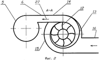
На фиг.1 показано устройство для очистки воздуха, общий вид; на фиг.2 - вид сверху, разрез А-А на общем виде.Figure 1 shows a device for air purification, General view; figure 2 is a top view, section aa in a general view.
Устройство (фиг.1) содержит фильтр тонкой очистки (1), вентилятор (2), пылеосадитель (3) с пылезаборником (4).The device (figure 1) contains a fine filter (1), a fan (2), a dust collector (3) with a dust intake (4).
Фильтр тонкой очистки (1) выполнен в виде цилиндрического корпуса (5) с входным тангенциальным патрубком (6) (фиг.2), пылесборника (7) с разгрузочным устройством (8), фильтрующего элемента (9), установленного внутри защитного кожуха (10) с выходным патрубком (11).The fine filter (1) is made in the form of a cylindrical body (5) with an inlet tangential branch pipe (6) (Fig. 2), a dust collector (7) with an unloading device (8), a filter element (9) installed inside the protective casing (10) ) with outlet pipe (11).
Вентилятор (2), жестко закрепленный на крышке пылеосадителя (3), имеет рабочее колесо с лопатками (12), улитку (13) и выходной патрубок (14) (фиг.2), который жестко соединен с входным тангенциальным патрубком (6) цилиндрического корпуса (5) фильтра тонкой очистки (1) для короткого пути прохода скопившихся твердых примесей на контуре наружной границы воздушного потока под действием центробежных сил в улитке (13) вентилятора (2) и для омывания этим контуром воздушного потока внутренней стенки цилиндрического корпуса (5) фильтра тонкой очистки (1).The fan (2), rigidly mounted on the dust collector cover (3), has an impeller with blades (12), a scroll (13) and an outlet pipe (14) (Fig. 2), which is rigidly connected to the inlet tangential pipe (6) of a cylindrical case (5) of the fine filter (1) for a short path of passage of accumulated solid impurities on the contour of the outer boundary of the air flow under the action of centrifugal forces in the cochlea (13) of the fan (2) and for washing this contour of the air flow of the inner wall of the cylindrical body (5) fine filter (1).
Пылеосадитель (3) выполнен в виде цилиндрического корпуса (15) с входным тангенциальным патрубком (16), соединенным с пылезаборником (4), конуса (17) с разгрузочным клапаном (18), крышки (19) с отверстием (20) и конусного сопла (21), размещенного внутри цилиндрического корпуса (15) пылеосадителя (3), причем конус сопла (21) проходит через отверстие (20) в крышке (19) пылеосадителя (3) и входит в вентилятор (2), образуя конусом сопла (21) над крышкой (19) входной патрубок (22) вентилятора (2), а под крышкой (19) внутри цилиндрического корпуса (15) пылеосадителя (3) сопло (21) образовало инерционную (23), осадительную (24) камеры и кольцевую щель (25) для прохода загрязненного тонкослойного воздушного потока (26) между наружной стенкой сопла (21) и внутренней стенкой цилиндрического корпуса (15) пылеосадителя (3).The dust collector (3) is made in the form of a cylindrical body (15) with an inlet tangential branch pipe (16) connected to the dust intake (4), a cone (17) with an unloading valve (18), a cover (19) with an opening (20) and a cone nozzle (21) located inside the cylindrical housing (15) of the dust collector (3), the cone of the nozzle (21) passing through the hole (20) in the cover (19) of the dust collector (3) and enters the fan (2), forming a nozzle cone (21) ) above the cover (19) of the inlet pipe (22) of the fan (2), and under the cover (19) inside the cylindrical body (15) of the dust collector (3), the nozzle (21) is shaped alo flywheel (23), settling (24) of the chamber and an annular gap (25) for the passage of a thin contaminated air stream (26) of the nozzle between the outer wall (21) and the inner wall of the cylindrical housing (15) precipitator (3).
Устройство работает следующим образом.The device operates as follows.
Загрязненный воздушный поток поступает через заборник (4), входной тангенциальный патрубок (16) в инерционную камеру (23) цилиндрического корпуса (15), закручивается в камере (23) вокруг сопла (21), проходит сверху вниз через кольцевую щель (25) в виде тонкослойного загрязненного воздушного потока (26) и выбрасывается в осадительную камеру (24), омывая контуром наружной границы загрязненного тонкослойного потока (26) внутреннюю стенку цилиндрического корпуса (15). При этом твердые частицы (примеси) при трении о внутреннюю стенку цилиндрического корпуса (15) теряют скорость, отделяются от потока и стекают по стенке корпуса (15) конуса (17) на разгрузочный клапан (18), а значительно очищенный воздушный поток из осадительной камеры (24) через сопло (21), входной патрубок (22) поступает в улитку (13) вентилятора (2), где за счет вращения рабочего колеса с лопатками (12) воздушный поток вращается в улитке (13), и твердые частицы (примеси) под действием центробежных сил сепарируются на периферийную стенку улитки (13), и выносятся из улитки (13) твердые примеси в виде скопившихся на контуре наружной границы воздушного потока (27) через выходной патрубок (14) вентилятора (2), и в таком виде воздушный поток (27) поступает через входной тангенциальный патрубок (6) в цилиндрический корпус (5) фильтра тонкой очистки (1), закручивается в нем, омывая контуром наружной границы воздушного потока (27) со скопившимися твердыми примесями, внутреннюю стенку цилиндрического корпуса (5) фильтра тонкой очистки (1). При этом твердые примеси при трении о внутреннюю стенку цилиндрического корпуса (5) теряют скорость, отделяются от потока и стекают по стенке корпуса (5) пылесборника (7) в разгрузочное устройство (8), а дополнительно очищенный воздух из цилиндрического корпуса (5) поступает в фильтрующий элемент (9), очищается в нем, проходит под защитным кожухом (10) и через выходной патрубок (11) выбрасывается наружу.The contaminated air stream enters through the intake (4), the tangential inlet pipe (16) into the inertia chamber (23) of the cylindrical body (15), is twisted in the chamber (23) around the nozzle (21), passes from top to bottom through the annular gap (25) into in the form of a thin-layer contaminated air stream (26) and is discharged into the precipitation chamber (24), washing the inner wall of the cylindrical body (15) with a contour of the outer boundary of the contaminated thin-layer stream (26). In this case, solid particles (impurities) during friction against the inner wall of the cylindrical body (15) lose speed, are separated from the flow and flow down the wall of the body (15) of the cone (17) to the discharge valve (18), and the significantly cleaned air stream from the precipitation chamber (24) through the nozzle (21), the inlet pipe (22) enters the scroll (13) of the fan (2), where due to the rotation of the impeller with blades (12), the air flow rotates in the scroll (13), and solid particles (impurities ) under the action of centrifugal forces are separated on the peripheral wall of the cochlea (13), and carried out solid impurities from the cochlea (13) in the form of air flow (27) accumulated on the outer boundary boundary circuit (27) through the outlet pipe (14) of the fan (2), and in this form the air stream (27) enters through the cylindrical inlet pipe (6) into the cylindrical the case (5) of the fine filter (1), twists in it, washing with the outline of the outer boundary of the air flow (27) with accumulated solid impurities, the inner wall of the cylindrical body (5) of the fine filter (1). In this case, solid impurities during friction against the inner wall of the cylindrical body (5) lose speed, are separated from the flow and flow down the wall of the body (5) of the dust collector (7) into the unloading device (8), and additionally purified air from the cylindrical body (5) enters into the filter element (9), it is cleaned in it, passes under the protective cover (10) and is thrown out through the outlet pipe (11).
Использование установки с фильтром тонкой очистки, вентилятором и пылеосадителем позволяет значительно повысить степень улавливания твердых примесей из воздушного потока.Using the installation with a fine filter, fan and dust separator can significantly increase the degree of capture of solid impurities from the air stream.
Claims (1)
Priority Applications (1)
| Application Number | Priority Date | Filing Date | Title |
|---|---|---|---|
| RU2004118140/15A RU2279321C2 (en) | 2004-06-15 | 2004-06-15 | Device for the air purification |
Applications Claiming Priority (1)
| Application Number | Priority Date | Filing Date | Title |
|---|---|---|---|
| RU2004118140/15A RU2279321C2 (en) | 2004-06-15 | 2004-06-15 | Device for the air purification |
Publications (1)
| Publication Number | Publication Date |
|---|---|
| RU2279321C2 true RU2279321C2 (en) | 2006-07-10 |
Family
ID=36830817
Family Applications (1)
| Application Number | Title | Priority Date | Filing Date |
|---|---|---|---|
| RU2004118140/15A RU2279321C2 (en) | 2004-06-15 | 2004-06-15 | Device for the air purification |
Country Status (1)
| Country | Link |
|---|---|
| RU (1) | RU2279321C2 (en) |
-
2004
- 2004-06-15 RU RU2004118140/15A patent/RU2279321C2/en not_active IP Right Cessation
Similar Documents
| Publication | Publication Date | Title |
|---|---|---|
| US4198290A (en) | Dust separating equipment | |
| KR101359800B1 (en) | A device and a method for cleaning of a gas | |
| RU2234232C2 (en) | Grid for cyclone-type dust catching device of vacuum cleaner (versions) | |
| CN211069511U (en) | Leading filtering formula wet dedusting fan | |
| WO2003084642A1 (en) | Dust collector | |
| KR20080025234A (en) | Dust collector | |
| JP2017042733A (en) | Fine particle separation device | |
| RU2279321C2 (en) | Device for the air purification | |
| KR102105600B1 (en) | Double cyclone dust cleaner | |
| CN113750654B (en) | Nested multi-rotor cyclone dust removal device | |
| RU2260470C1 (en) | Vortex-type dust collector | |
| CN211302504U (en) | Multi-air-duct comprehensive dust removal system | |
| RU2324543C1 (en) | Cyclon | |
| US3985526A (en) | Dust collector with spaced volutes | |
| RU2144436C1 (en) | Dust separator with flow former | |
| RU2050940C1 (en) | Dust separator | |
| JP2010279910A (en) | Apparatus for removing oil mist | |
| KR200432138Y1 (en) | dust collector | |
| WO2004041442A1 (en) | Separator | |
| RU2297871C1 (en) | Device for purification of the gas | |
| RU124323U1 (en) | TWO STAGE ICE CLEANER | |
| KR101525033B1 (en) | Centrifugal separation type axial dust collecting apparatus | |
| CN214698118U (en) | Multistage air filtering device | |
| RU2011403C1 (en) | Filter | |
| SU956033A1 (en) | Turbocyclone |
Legal Events
| Date | Code | Title | Description |
|---|---|---|---|
| MM4A | The patent is invalid due to non-payment of fees |
Effective date: 20070616 |