RU2279103C2 - Method for finding defects of stator holding parts on working electric machine - Google Patents
Method for finding defects of stator holding parts on working electric machine Download PDFInfo
- Publication number
- RU2279103C2 RU2279103C2 RU2004121541/09A RU2004121541A RU2279103C2 RU 2279103 C2 RU2279103 C2 RU 2279103C2 RU 2004121541/09 A RU2004121541/09 A RU 2004121541/09A RU 2004121541 A RU2004121541 A RU 2004121541A RU 2279103 C2 RU2279103 C2 RU 2279103C2
- Authority
- RU
- Russia
- Prior art keywords
- stator
- defects
- frequency
- harmonics
- vibro
- Prior art date
Links
- 230000007547 defect Effects 0.000 title claims abstract description 49
- 238000000034 method Methods 0.000 title claims abstract description 22
- 238000005259 measurement Methods 0.000 claims description 3
- 238000003745 diagnosis Methods 0.000 abstract description 2
- 230000003094 perturbing effect Effects 0.000 abstract description 2
- 230000000694 effects Effects 0.000 abstract 1
- 230000010355 oscillation Effects 0.000 abstract 1
- 239000000126 substance Substances 0.000 abstract 1
- 230000001133 acceleration Effects 0.000 description 15
- 230000003313 weakening effect Effects 0.000 description 13
- 238000004804 winding Methods 0.000 description 12
- 238000011161 development Methods 0.000 description 11
- 238000001228 spectrum Methods 0.000 description 10
- 230000007797 corrosion Effects 0.000 description 4
- 238000005260 corrosion Methods 0.000 description 4
- 238000005299 abrasion Methods 0.000 description 3
- 230000008878 coupling Effects 0.000 description 3
- 238000010168 coupling process Methods 0.000 description 3
- 238000005859 coupling reaction Methods 0.000 description 3
- 238000001514 detection method Methods 0.000 description 2
- 239000000428 dust Substances 0.000 description 2
- 230000005284 excitation Effects 0.000 description 2
- 238000007689 inspection Methods 0.000 description 2
- 238000009413 insulation Methods 0.000 description 2
- 238000012806 monitoring device Methods 0.000 description 2
- 230000003321 amplification Effects 0.000 description 1
- 238000004364 calculation method Methods 0.000 description 1
- 230000006378 damage Effects 0.000 description 1
- 238000006073 displacement reaction Methods 0.000 description 1
- 238000013399 early diagnosis Methods 0.000 description 1
- 238000004870 electrical engineering Methods 0.000 description 1
- ZZUFCTLCJUWOSV-UHFFFAOYSA-N furosemide Chemical compound C1=C(Cl)C(S(=O)(=O)N)=CC(C(O)=O)=C1NCC1=CC=CO1 ZZUFCTLCJUWOSV-UHFFFAOYSA-N 0.000 description 1
- UQSXHKLRYXJYBZ-UHFFFAOYSA-N iron oxide Inorganic materials [Fe]=O UQSXHKLRYXJYBZ-UHFFFAOYSA-N 0.000 description 1
- 235000013980 iron oxide Nutrition 0.000 description 1
- VBMVTYDPPZVILR-UHFFFAOYSA-N iron(2+);oxygen(2-) Chemical class [O-2].[Fe+2] VBMVTYDPPZVILR-UHFFFAOYSA-N 0.000 description 1
- 238000012423 maintenance Methods 0.000 description 1
- 238000013178 mathematical model Methods 0.000 description 1
- 238000012544 monitoring process Methods 0.000 description 1
- 210000003739 neck Anatomy 0.000 description 1
- 238000003199 nucleic acid amplification method Methods 0.000 description 1
- 230000035939 shock Effects 0.000 description 1
- 238000012546 transfer Methods 0.000 description 1
Images
Landscapes
- Manufacture Of Motors, Generators (AREA)
- Measurement Of Mechanical Vibrations Or Ultrasonic Waves (AREA)
Abstract
Description
Изобретение относится к области электротехники, к способам диагностики электрических машин, преимущественно турбо- и гидрогенераторов электростанций.The invention relates to the field of electrical engineering, to methods for diagnosing electrical machines, mainly turbo and hydro generators of power plants.
Дефекты ослабления узлов крепления статора, а именно его сердечника и обмотки, являются частой причиной аварийных остановов генераторов электростанций. Эти обстоятельства делают актуальной проблему ранней диагностики дефектов статора на работающей электрической машине.Defects in the weakening of the stator mounts, namely its core and windings, are a frequent cause of emergency shutdowns of power plant generators. These circumstances make urgent the problem of early diagnosis of stator defects on a working electric machine.
Известен способ обнаружения дефектов по авт. св. СССР №1080091, в котором изменяют уровень возбуждения генератора, а также измеряют с помощью вибродатчиков, установленных на спинке сердечника статора, диагностический параметр виброакустических колебаний, реагирующий на появление виброударных процессов в статоре, а именно среднеквадратическое значение измеряемого виброакустического сигнала. По значению диагностического параметра судят о наличии дефектов статора.A known method for detecting defects according to ed. St. USSR No. 1080091, in which the level of excitation of the generator is changed, and also with the help of vibration sensors installed on the back of the stator core, the diagnostic parameter of vibro-acoustic vibrations responding to the appearance of vibro-shock processes in the stator, namely the rms value of the measured vibro-acoustic signal. By the value of the diagnostic parameter, the presence of stator defects is judged.
Недостаток этого способа в том, что не обеспечиваются обнаружение ослабления креплений обмотки статора и ослабление узлов крепления сердечника статора к корпусу генератора. Кроме того, этот способ не применим на машине, работающей в сети, так как работа в сети требует поддержания практически неизменного уровня напряжения и возбуждения.The disadvantage of this method is that it does not detect the weakening of the fastenings of the stator winding and the weakening of the attachment points of the stator core to the generator housing. In addition, this method is not applicable on a machine operating in the network, since network operation requires the maintenance of a practically constant voltage and excitation level.
Наиболее близок к заявляемому способ обнаружения дефектов, описанный в ст.: "Григорьев А.В., Осотов В.Н., Ямпольский Д.А. О вибрационном контроле технического состояния статоров турбогенераторов ТГВ-300. - Электрические станции, 1998, №8. С.27-35.". В этом способе измеряют параметр виброакустических колебаний корпуса турбогенератора, характеризующий интенсивность гармоник виброакустических колебаний в диапазоне частот 200 Гц≤f≤1000 Гц, а именно среднеквадратическое отклонение виброускорения, и по значению параметра судят о наличии дефектов крепления сердечника статора.Closest to the claimed method for detecting defects, described in the article: "Grigoryev A.V., Osotov V.N., Yampolsky D.A. On vibration monitoring of the technical condition of the stators of turbogenerators TGV-300. - Electrical stations, 1998, No. 8 . P. 27-35. " In this method, the parameter of vibroacoustic vibrations of the turbogenerator body is measured, which characterizes the harmonic intensity of vibroacoustic vibrations in the frequency range 200 Hz≤f≤1000 Hz, namely the standard deviation of the vibration acceleration, and the stator core is fixed for defects.
Недостаток этого способа в том, что не обеспечивается обнаружение ослабления креплений обмотки статора и распознавание дефектов крепления обмотки и дефектов крепления сердечника статора.The disadvantage of this method is that it does not detect the weakening of the fastenings of the stator winding and recognition of defects in the fastening of the winding and defects in the fastening of the stator core.
Цель изобретения - повышение достоверности диагностирования дефектов узлов крепления статора на работающем генераторе посредством обеспечения обнаружения и распознавания различных видов дефектов, включая дефекты крепления обмотки статора и опасные стадии развития дефектов крепления сердечника.The purpose of the invention is to increase the reliability of diagnosing defects in stator attachment points on a running generator by providing detection and recognition of various types of defects, including stator winding fastening defects and dangerous stages of core fastening defects.
Для достижения поставленной цели в способе обнаружения дефектов статора на работающей машине, в котором измеряют на конструктивных частях статора интенсивность гармоник виброакустических колебаний, определяют диагностический параметр, характеризующий наличие виброударных процессов в статоре, и устанавливают по значению диагностического параметра наличие дефектов статора. С целью повышения достоверности диагностирования и распознавания дефектов определяют параметры частотного диапазона, в котором расположены гармоники виброакустических колебаний, и распознают вид дефекта по расположению указанного диапазона в области частот. Например, определяют верхнюю частоту частотного диапазона, в котором расположены гармоники виброакустических колебаний, и распознают вид дефекта по значению верхней частоты частотного диапазона. Для обеспечения обнаружения значимых дефектов в качестве параметра виброакустических колебаний, характеризующего наличие виброударных процессов в статоре, измеряют интенсивность гармоник виброакустических колебаний на частотах выше 1000 Гц, например измеряют мощность гармоник виброакустического сигнала М(1050-2000) в диапазоне частот 1050 Гц≤f≤2000 Гц, и судят о появлении значимых дефектов в узлах крепления сердечника по величине параметра М(1050-2000).To achieve the goal in a method for detecting stator defects on a running machine, in which the intensity of harmonics of vibroacoustic vibrations is measured on the structural parts of the stator, a diagnostic parameter characterizing the presence of vibro-shock processes in the stator is determined, and the presence of stator defects is determined by the value of the diagnostic parameter. In order to increase the reliability of diagnosis and recognition of defects, the parameters of the frequency range in which harmonics of vibroacoustic vibrations are located are determined and the type of defect is recognized by the location of the specified range in the frequency domain. For example, the upper frequency of the frequency range in which harmonics of vibroacoustic vibrations are located is determined, and the type of defect is recognized by the value of the upper frequency of the frequency range. To ensure the detection of significant defects as a parameter of vibro-acoustic vibrations characterizing the presence of vibro-shock processes in the stator, the harmonic intensity of vibro-acoustic vibrations is measured at frequencies above 1000 Hz, for example, the harmonic power of the vibro-acoustic signal M (1050-2000) is measured in the frequency range 1050 Hz≤f≤2000 Hz, and judge the appearance of significant defects in the attachment points of the core by the value of the parameter M (1050-2000) .
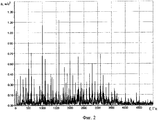
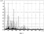
На фиг.1 показан вид спектра виброускорений корпуса генератора, сопровождающий начальную стадию развития дефекта крепления сердечника с появлением трения в узлах крепления. На фиг.2 показан вид спектра виброускорений корпуса генератора, сопровождающий вторую, опасную и значимую стадию развития дефекта крепления сердечника с появлением зазоров в узлах крепления сердечника. На фиг.3 показан вид спектра виброускорений корпуса генератора, имеющего ослабление крепления корзины лобовых дуг обмотки статора.Figure 1 shows a view of the spectrum of vibration acceleration of the generator housing, accompanying the initial stage of development of a core mounting defect with the appearance of friction in the mounting nodes. Figure 2 shows a view of the spectrum of vibration acceleration of the generator housing, accompanying the second, dangerous and significant stage of development of the core fastening defect with the appearance of gaps in the core fastening nodes. Figure 3 shows a view of the spectrum of vibration acceleration of the generator housing, having a weakening of the mounting basket of the frontal arches of the stator winding.
Сущность происходящих процессов сводится к следующему.The essence of the ongoing processes is as follows.
Спектр виброускорений корпуса исправного генератора имеет одну гармонику на частоте возмущающей силы, равной частоте магнитного поля машины, это номинально 100 Гц. Ослабление посадки сердечника статора на стяжные призмы корпуса приводит в условиях вибрации к относительным перемещениям (проскальзыванию) сердечника и наборной призмы в узлах крепления типа "ласточкин хвост стяжной призмы - трапецевидный паз (Т-паз) спинки сердечника статора". Происходят истирание контактирующих поверхностей и дальнейшее ослабление посадки сердечника на стяжные призмы и усиление вибрации. Это начальная стадия развития дефекта крепления сердечника. Она проявляет себя контактной коррозией в виде бурой пыли (окислы железа) в местах посадки. Расчеты, проведенные авторами-заявителями на математической модели турбогенератора, показали, что начальная стадия развития дефекта сопровождается появлением в спектре виброускорений корпуса генератора в диапазоне частот до 1000 Гц ниспадающего ряда гармоник, кратных частоте возмущающей силы, номинально равной 100 Гц. Вид спектра виброускорений корпуса генератора, сопровождающий начальную стадию развития дефекта крепления сердечника, показан на фиг.1. В таком состоянии возможна длительная и надежная работа электрической машины. Поэтому нет необходимости выявлять начальную стадию развития дефекта, например, устройствами мониторинга.The vibration acceleration spectrum of a working generator body has one harmonic at a frequency of disturbing force equal to the frequency of the machine’s magnetic field, this is nominally 100 Hz. The weakening of the landing of the stator core on the coupling prisms of the housing leads to relative displacements (slippage) of the core and composing prism in the fastening nodes of the type “dovetail of the coupling prism - trapezoidal groove (T-groove) of the stator core back” under vibration conditions. Abrasion of the contacting surfaces and further weakening of the core landing on the coupling prisms and amplification of vibration occur. This is the initial stage of development of the core fixing defect. It manifests itself as contact corrosion in the form of brown dust (iron oxides) at the landing sites. Calculations performed by the applicants on a mathematical model of a turbogenerator showed that the initial stage of the development of the defect is accompanied by the appearance in the spectrum of vibration accelerations of the generator body in the frequency range up to 1000 Hz of a descending series of harmonics that are multiples of the frequency of the disturbing force, nominally 100 Hz. The view of the spectrum of vibration acceleration of the generator housing, accompanying the initial stage of development of the core fixing defect, is shown in Fig. 1. In this state, a long and reliable operation of the electric machine is possible. Therefore, there is no need to identify the initial stage of development of the defect, for example, by monitoring devices.
Развитие дефекта крепления сердечника приводит к выработке зазоров в узлах крепления и появлению ударных процессов в узлах крепления. Это вторая, опасная стадия развития дефекта. В силу импульсного характера передачи энергии такой процесс приводит к разрушению сварных швов и элементов крепления стяжных призм с корпусом генератора, ослаблению затяжки гаек стяжных призм и обрывам шеек стяжных призм в местах сопряжения с нажимными плитами и, в конечном счете, к аварии генератора. Требуется устранение дефекта для обеспечения надежной работы машины. Поэтому вторая стадия развития дефекта является значимой и подлежит обязательному выявлению. Экспериментальные исследования, проведенные авторами-заявителями, показали, что вторая стадия дефекта сопровождается появлением в спектре виброускорений корпуса генератора ряда гармоник, кратных частоте возмущающей силы, номинально 100 Гц, на частотах, существенно больших 1000 Гц. Вид спектра виброускорений корпуса генератора, сопровождающий вторую, опасную стадию развития дефекта крепления сердечника, показан на фиг.2. При выводе в ремонт и осмотре этого генератора обнаружены следы обильной контактной коррозии в узлах крепления сердечника к корпусу, обрывы контровочных сварочных швов и откручивание крепежных гаек. Особенностью проявления второй стадии дефекта является длинный ряд кратных гармоник, захватывающий область частот более 3000 Гц.The development of a core fastening defect leads to the development of gaps in the fastening nodes and the appearance of shock processes in the fastening nodes. This is the second, dangerous stage of the development of the defect. Due to the pulsed nature of energy transfer, such a process leads to the destruction of welds and fastening elements of the tie-rod prisms with the generator body, a weakening of the tightening of the tie-rod prism nuts and breaks of the tie-rod prism necks at the interfaces with the pressure plates and, ultimately, to the generator accident. Corrective action is required to ensure reliable operation of the machine. Therefore, the second stage of development of the defect is significant and must be identified. Experimental studies conducted by the applicant authors showed that the second stage of the defect is accompanied by the appearance of a number of harmonics in the spectrum of vibration accelerations of the generator casing, multiples of the frequency of the disturbing force, nominally 100 Hz, at frequencies substantially greater than 1000 Hz. The view of the spectrum of vibration acceleration of the generator housing, accompanying the second, dangerous stage of development of the core fixing defect, is shown in FIG. 2. When this generator was taken out for repair and inspection, traces of abundant contact corrosion were found in the attachment points of the core to the body, breaks in the locking welds and loosening of the fixing nuts. A feature of the manifestation of the second stage of the defect is a long series of multiple harmonics, capturing a frequency region of more than 3000 Hz.
Ослабление креплений обмотки статора приводит к истиранию изоляции в узлах ее крепления с появлением следов контактной коррозии в виде наносов пыли желтого цвета. Это продукты истирания изоляции. Экспериментальные исследования, проведенные авторами-заявителями, показали, что дефект ослабления креплений обмотки статора также сопровождается появлением в спектре виброускорений корпуса генератора ряда гармоник, кратных частоте возмущающей силы на частотах, больших 1000 Гц, но не более 3000 Гц. Вид спектра виброускорений корпуса генератора, имеющего ослабление крепления корзины лобовых дуг обмотки статора, показан на фиг.3. При выводе в ремонт и осмотре этого генератора обнаружены следы обильной контактной коррозии в узлах крепления корзины лобовых дуг обмотки статора. Особенностью проявления такого дефекта является ряд кратных гармоник, захватывающий область до 3000 Гц.The weakening of the fastening of the stator winding leads to abrasion of the insulation in the nodes of its fastening with the appearance of traces of contact corrosion in the form of yellow dust deposits. These are products of abrasion insulation. Experimental studies conducted by the applicant applicants have shown that the defect in the weakening of the stator winding fasteners is also accompanied by the appearance of a number of harmonics in the spectrum of vibration accelerations of the generator housing, multiples of the frequency of the disturbing force at frequencies greater than 1000 Hz, but not more than 3000 Hz. The view of the spectrum of vibration acceleration of the generator housing, having a weakening of the mounting basket of the frontal arches of the stator winding, is shown in figure 3. When the generator was taken out for repair and inspection, traces of abundant contact corrosion were found in the attachment points of the basket of frontal arches of the stator winding. A feature of the manifestation of such a defect is a number of multiple harmonics, which captures the region up to 3000 Hz.
Приведенные данные теоретических и экспериментальных исследований служат доказательством возможности осуществления изобретения.The data of theoretical and experimental studies are evidence of the possibility of carrying out the invention.
Способ осуществляется следующим образом, например, на турбогенераторе ТВВ-320-2. Генератор работает в сети с нагрузкой 300 МВт, 120 МВАр. Частота магнитного поля и, следовательно, возмущающих сил магнитного тяжения в машине 100 Гц.The method is as follows, for example, on a turbogenerator TVV-320-2. The generator operates in a network with a load of 300 MW, 120 MVAr. The frequency of the magnetic field and, therefore, the disturbing forces of magnetic traction in the machine is 100 Hz.
Вариант 1. Для обнаружения дефектов статора с помощью известной аппаратуры и известными методами, например, с помощью виброизмерительного комплекса MIC-300M, оснащенный датчиками виброускорения АР-40 с магнитным крепежом, производства НПП "МЕРА", на корпусе статора измеряют значение амплитуд гармоник виброускорений на частотах до 5000 Гц. Результаты измерений приведены в графической форме на фиг.3. По результатам измерений с помощью программных средств виброизмерительного комплекса MIC-300M определяют значение виброакустического диагностического параметра М(1050-2000), представляющего собой мощность кратных гармоник виброускорений в диапазоне частот 1050 Гц≤f≤2000 Гц. Измеренное значение диагностического параметра составляет 2,64 (м/сек2)2, что существенно превышает уровень нормального функционирования, равный 0,5 (м/сек2)2. Делают вывод о появлении на генераторе дефекта в узлах крепления статора. Для распознавания дефекта определяют на спектрограмме, показанной на фиг.3, верхнюю частоту ряда гармоник, кратных частоте возмущающей силы 100 Гц, по критерию: значения амплитуд не менее двух целочисленно кратных частоте 100 Гц гармоник, следующих за последней гармоникой ряда, не должны превышать 0,20 от значения максимальной амплитуды кратных гармоник в ряду. Из фиг.3 следует, что максимальную амплитуду имеет гармоника на частоте 500 Гц. Ее значение равно 1,38 м/с2. Значение величины в 0,20 от 1,38 м/с2 равно 0,276 м/с2. Тогда последней гармоникой в ряду является гармоника на частоте 1800 Гц с амплитудой 0,71 м/с2, а верхняя частота ряда кратных гармоник равна 1800 Гц, что меньше пороговой частоты распознавания 3000 Гц. Следовательно, обнаруженный дефект является дефектом ослабления креплений обмотки статора.Option 1. To detect stator defects using known equipment and known methods, for example, using the MIC-300M vibration measuring complex equipped with AR-40 vibration acceleration sensors with magnetic fasteners manufactured by NPP MERA, the values of the amplitudes of the vibration acceleration harmonics are measured on the stator housing frequencies up to 5000 Hz. The measurement results are shown in graphical form in figure 3. According to the measurement results using the software of the vibration measuring complex MIC-300M determine the value of the vibro-acoustic diagnostic parameter M (1050-2000) , which is the power of multiple harmonics of vibration acceleration in the frequency range 1050 Hz≤f≤2000 Hz. The measured value of the diagnostic parameter is 2.64 (m / s 2 ) 2 , which significantly exceeds the level of normal functioning, equal to 0.5 (m / s 2 ) 2 . Make a conclusion about the appearance on the generator of a defect in the stator mounts. For defect recognition, the upper frequency of a series of harmonics that are multiples of the frequency of the perturbing force of 100 Hz is determined on the spectrogram shown in Fig. 3 according to the criterion: the amplitudes of at least two integer multiples of the frequency of 100 Hz of harmonics following the last harmonic of the series should not exceed 0 , 20 from the value of the maximum amplitude of multiple harmonics in a row. From figure 3 it follows that the maximum amplitude has a harmonic at a frequency of 500 Hz. Its value is 1.38 m / s 2 . The value of 0.20 from 1.38 m / s 2 is equal to 0.276 m / s 2 . Then the last harmonic in the series is the harmonic at a frequency of 1800 Hz with an amplitude of 0.71 m / s 2 , and the upper frequency of a number of multiple harmonics is 1800 Hz, which is less than the threshold recognition frequency of 3000 Hz. Therefore, the detected defect is a defect in the loosening of the stator winding fasteners.
Вариант 2. На том же генераторе с помощью тех же технических средств дополнительно к диагностическому параметру M(1050-2000) определяют диагностический параметр М(2000-3000), представляющий собой мощность кратных гармоник виброускорений в диапазоне частот 2000 Гц<f≤3000 Гц.Option 2. On the same generator using the same technical means, in addition to the diagnostic parameter M (1050-2000) , the diagnostic parameter M (2000-3000) is determined, which is the power of multiple harmonics of vibration acceleration in the
Параметр М(2000-3000) равен 0,38 (м/сек2)2, что ниже уровня нормального функционирования 0,5 (м/сек2)2 , свидетельствует об отсутствии значимых кратных гармоник в частотном диапазоне 2000 Гц<f≤3000 Гц. Следовательно, верхняя частота ряда кратных гармоник не превышает пороговой частоты распознавания 3000 Гц, а обнаруженный дефект является дефектом ослабления креплений обмотки статора. Вариант 2 наиболее приемлем для реализации в устройствах мониторинга.The parameter M (2000-3000) is 0.38 (m / s 2 ) 2 , which is below the normal functioning level of 0.5 (m / s 2 ) 2 , indicates the absence of significant multiple harmonics in the frequency range of 2000 Hz <f≤3000 Hz Therefore, the upper frequency of a number of multiple harmonics does not exceed the threshold recognition frequency of 3000 Hz, and the detected defect is a defect in the weakening of the stator winding fasteners. Option 2 is most suitable for implementation in monitoring devices.
Следует отметить, что верхняя частота ряда гармоник на фиг.2 равна 3600 Гц, что превышает частоту распознавания 3000 Гц и указывает на ослабление креплений сердечника статора.It should be noted that the upper frequency of a number of harmonics in FIG. 2 is 3600 Hz, which exceeds the recognition frequency of 3000 Hz and indicates a weakening of the stator core mounts.
Claims (2)
Priority Applications (1)
| Application Number | Priority Date | Filing Date | Title |
|---|---|---|---|
| RU2004121541/09A RU2279103C2 (en) | 2004-07-15 | 2004-07-15 | Method for finding defects of stator holding parts on working electric machine |
Applications Claiming Priority (1)
| Application Number | Priority Date | Filing Date | Title |
|---|---|---|---|
| RU2004121541/09A RU2279103C2 (en) | 2004-07-15 | 2004-07-15 | Method for finding defects of stator holding parts on working electric machine |
Publications (2)
| Publication Number | Publication Date |
|---|---|
| RU2004121541A RU2004121541A (en) | 2006-01-27 |
| RU2279103C2 true RU2279103C2 (en) | 2006-06-27 |
Family
ID=36047155
Family Applications (1)
| Application Number | Title | Priority Date | Filing Date |
|---|---|---|---|
| RU2004121541/09A RU2279103C2 (en) | 2004-07-15 | 2004-07-15 | Method for finding defects of stator holding parts on working electric machine |
Country Status (1)
| Country | Link |
|---|---|
| RU (1) | RU2279103C2 (en) |
Citations (6)
| Publication number | Priority date | Publication date | Assignee | Title |
|---|---|---|---|---|
| US3707038A (en) * | 1970-11-18 | 1972-12-26 | Skf Ind Trading & Dev | Method for manufacturing stator units of electric rotary machines |
| SU1444686A1 (en) * | 1987-12-09 | 1988-12-15 | Ленинградское Производственное Электромашиностроительное Объединение "Электросила" Им.С.М.Кирова | Method of testing stator core of powerful electric machine for heating |
| EP0552991A3 (en) * | 1992-01-23 | 1994-04-13 | Ontario Hydro | |
| RU2113754C1 (en) * | 1996-09-20 | 1998-06-20 | Открытое акционерное общество "Свердловэнерго" | Method for checking pressing of core of electric motor stator |
| US6636823B1 (en) * | 1999-09-30 | 2003-10-21 | Rockwell Automation Technologies, Inc. | Method and apparatus for motor fault diagnosis |
| RU2216841C2 (en) * | 2002-01-09 | 2003-11-20 | Назолин Андрей Леонидович | Method for detecting stator faults in running electrical machine |
-
2004
- 2004-07-15 RU RU2004121541/09A patent/RU2279103C2/en active
Patent Citations (6)
| Publication number | Priority date | Publication date | Assignee | Title |
|---|---|---|---|---|
| US3707038A (en) * | 1970-11-18 | 1972-12-26 | Skf Ind Trading & Dev | Method for manufacturing stator units of electric rotary machines |
| SU1444686A1 (en) * | 1987-12-09 | 1988-12-15 | Ленинградское Производственное Электромашиностроительное Объединение "Электросила" Им.С.М.Кирова | Method of testing stator core of powerful electric machine for heating |
| EP0552991A3 (en) * | 1992-01-23 | 1994-04-13 | Ontario Hydro | |
| RU2113754C1 (en) * | 1996-09-20 | 1998-06-20 | Открытое акционерное общество "Свердловэнерго" | Method for checking pressing of core of electric motor stator |
| US6636823B1 (en) * | 1999-09-30 | 2003-10-21 | Rockwell Automation Technologies, Inc. | Method and apparatus for motor fault diagnosis |
| RU2216841C2 (en) * | 2002-01-09 | 2003-11-20 | Назолин Андрей Леонидович | Method for detecting stator faults in running electrical machine |
Non-Patent Citations (1)
| Title |
|---|
| ГРИГОРЬЕВ А.В., ОСТОВ В.Н., ЯМПОЛЬСКИЙ Д.А. О вибрационном контроле технического состояния статоров турбогенератора ТГВ-300. Электрические станции. 1999, №8, с.27-35. * |
Also Published As
| Publication number | Publication date |
|---|---|
| RU2004121541A (en) | 2006-01-27 |
Similar Documents
| Publication | Publication Date | Title |
|---|---|---|
| Watson et al. | Condition monitoring of the power output of wind turbine generators using wavelets | |
| JP5565120B2 (en) | High-frequency electromagnetic vibration component removal method and high-frequency electromagnetic vibration component removal device, rolling bearing diagnosis method and bearing diagnosis device for a rotating machine | |
| CN109297716B (en) | Vibration fault diagnosis method for double-fed wind driven generator | |
| US10473708B2 (en) | Methods and systems for real-time monitoring of the insulation state of wind-powered generator windings | |
| Patil et al. | Vibration analysis of electrical rotating machines using FFT: A method of predictive maintenance | |
| Moiz et al. | Health monitoring of three-phase induction motor using current and vibration signature analysis | |
| CN103998775A (en) | Method for determining mechanical damage to a rotor blade of a wind power plant | |
| Fenger et al. | Development of a tool to detect faults in induction motors via current signature analysis | |
| JPH05142033A (en) | Monitoring equipment for plant equipment | |
| CN103261904A (en) | Monitoring and fault diagnosis of an electric machine | |
| Shi et al. | Purification and feature extraction of shaft orbits for diagnosing large rotating machinery | |
| Schreiber | Induction motor vibration diagnostics with the use of stator current analysis | |
| Kumar et al. | Sensitivity of rotor slot harmonics due to inter-turn fault in induction motors through vibration analysis | |
| RU2279103C2 (en) | Method for finding defects of stator holding parts on working electric machine | |
| Huang et al. | Angle misalignment detection and its suppression algorithm in rotor system based on speed signal | |
| Prasad et al. | Looseness identification of stator end windings of induction motor by modal test | |
| Shaeboub et al. | Detection and diagnosis of compound faults in induction motors using electric signals from variable speed drives | |
| Iorgulescu et al. | Vibration monitoring for diagnosis of electrical equipment's faults | |
| CN205593707U (en) | Turbo generator set high -and medium -voltage rotor dynamic balance optimizing apparatus | |
| He et al. | Detection of single-axis pitch bearing defect in a wind turbine using electrical signature analysis | |
| Güçlü et al. | Vibration analysis of induction motors with unbalanced loads | |
| Ali et al. | Test rig for the fault diagnosis of 3-phase small scale induction motor | |
| Sonje et al. | Fault diagnosis of induction motor using parks vector approach | |
| Harlisca et al. | Bearing faults condition monitoring-a literature survey | |
| Battulga et al. | Vibration-based identification of mechanical defects in induction motor-driven systems during the starting transient |
Legal Events
| Date | Code | Title | Description |
|---|---|---|---|
| QB4A | Licence on use of patent |
Effective date: 20061212 |