RU2276373C1 - Housing for electricity meter - Google Patents
Housing for electricity meter Download PDFInfo
- Publication number
- RU2276373C1 RU2276373C1 RU2005113215/28A RU2005113215A RU2276373C1 RU 2276373 C1 RU2276373 C1 RU 2276373C1 RU 2005113215/28 A RU2005113215/28 A RU 2005113215/28A RU 2005113215 A RU2005113215 A RU 2005113215A RU 2276373 C1 RU2276373 C1 RU 2276373C1
- Authority
- RU
- Russia
- Prior art keywords
- casing
- base
- housing according
- sealing
- circuit board
- Prior art date
Links
- 230000005611 electricity Effects 0.000 title description 2
- 238000007789 sealing Methods 0.000 claims abstract description 22
- 239000004020 conductor Substances 0.000 claims abstract description 7
- 238000003032 molecular docking Methods 0.000 claims description 4
- 239000000126 substance Substances 0.000 abstract 1
- 239000011521 glass Substances 0.000 description 2
- 238000009413 insulation Methods 0.000 description 2
- 238000004519 manufacturing process Methods 0.000 description 2
- 238000010079 rubber tapping Methods 0.000 description 2
- 230000015556 catabolic process Effects 0.000 description 1
- 238000010276 construction Methods 0.000 description 1
- 238000010586 diagram Methods 0.000 description 1
- 239000000428 dust Substances 0.000 description 1
- 238000004870 electrical engineering Methods 0.000 description 1
- 238000005265 energy consumption Methods 0.000 description 1
- 230000007613 environmental effect Effects 0.000 description 1
- 230000006698 induction Effects 0.000 description 1
- 238000007689 inspection Methods 0.000 description 1
- 238000009434 installation Methods 0.000 description 1
- 238000002955 isolation Methods 0.000 description 1
- 239000004973 liquid crystal related substance Substances 0.000 description 1
- 239000002184 metal Substances 0.000 description 1
- NJPPVKZQTLUDBO-UHFFFAOYSA-N novaluron Chemical compound C1=C(Cl)C(OC(F)(F)C(OC(F)(F)F)F)=CC=C1NC(=O)NC(=O)C1=C(F)C=CC=C1F NJPPVKZQTLUDBO-UHFFFAOYSA-N 0.000 description 1
- 239000004033 plastic Substances 0.000 description 1
- 230000036316 preload Effects 0.000 description 1
- 230000035939 shock Effects 0.000 description 1
- XLYOFNOQVPJJNP-UHFFFAOYSA-N water Substances O XLYOFNOQVPJJNP-UHFFFAOYSA-N 0.000 description 1
Images
Landscapes
- Casings For Electric Apparatus (AREA)
Abstract
Description
Изобретение относится к электроизмерительной технике, а именно к конструированию деталей и узлов счетчиков для учета электрической энергии, предназначенных для учета и контроля потребления электроэнергии в различных отраслях народного хозяйства.The invention relates to electrical engineering, in particular to the design of parts and components of meters for metering electric energy, intended for metering and control of electricity consumption in various sectors of the economy.
Известно электронное устройство для измерения энергопотребления, содержащее основание, снабженное средствами для подключения к контролируемой электрической сети и передней съемной крышкой со смотровым окном, плату с размещенными на ней электронными компонентами и цифровой индикатор, а также плоскую пружину, закрепленную на основании, а свободные ее конец жестко закреплен с платой (RU 2206098 С1, 10.06.2003).Known electronic device for measuring energy consumption, containing a base equipped with means for connecting to a controlled electrical network and a front removable cover with a viewing window, a circuit board with electronic components placed on it and a digital indicator, as well as a flat spring fixed to the base, and its free end rigidly fixed to the board (RU 2206098 C1, 06/10/2003).
Данная конструкция обеспечивает виброизоляцию компонентов счетчика, размещенных на плате, но она не обеспечивает полного контроля над всеми элементами, расположенными внутри счетчика, обладает сложностью в изготовлении.This design provides vibration isolation of the components of the meter placed on the board, but it does not provide complete control over all elements located inside the meter, it is difficult to manufacture.
Известно также электронное устройство для измерения электропотребления, содержащее основание, снабженное средствами для подключения к контролируемой электрической сети, и переднюю съемную крышку со смотровым окном, две платы, одна из которых жестко закреплена на основании, а другая прикреплена на первой плате посредством двух стоек (US 5450007, 1995).An electronic device for measuring power consumption is also known, comprising a base equipped with means for connecting to a controlled electrical network, and a front removable cover with a viewing window, two boards, one of which is rigidly fixed to the base, and the other is attached to the first board through two racks (US 5450007, 1995).
Недостатком такой конструкции является неудобное крепление плат, что характеризуется невысокой эксплуатационной надежностью.The disadvantage of this design is the inconvenient mounting of boards, which is characterized by low operational reliability.
Известен индукционный счетчик электрической энергии, содержащий прямоугольный корпус, включающий в себя цоколь с элементами крепления счетного механизма и печатной платы, кожух со смотровым окном, колодку с отсеками для зажимов проводов, закрепленную на приливе внизу цоколя (SU 1802344 А1, 15.03.1993).A known induction electric energy meter comprising a rectangular housing including a base with fasteners for a counting mechanism and a printed circuit board, a casing with a viewing window, a block with compartments for wire clips, mounted on a tide at the bottom of the base (SU 1802344 A1, 03/15/1993).
Недостатком данной конструкции счетчика является недостаточная герметизация узлов корпуса и электрических элементов счетчика, недостаточная эксплуатационная надежность в условиях вибраций и резких ударных нагрузок, сложность сборки, недостаточные изоляционные свойства.The disadvantage of this design of the meter is insufficient sealing of the nodes of the housing and electrical elements of the meter, insufficient operational reliability in conditions of vibration and sudden shock loads, the complexity of the assembly, insufficient insulation properties.
Технический результат, достигаемый в данном изобретении, заключается в точной фиксации на местах узлов однофазного счетчика, в обеспечении герметизации узлов счетчика, а также обеспечении полного контроля над всеми узлами прибора, высокой технологичности изготовления, сборки и ремонта, высоких изоляционных свойств, исключающих электрический пробой.The technical result achieved in this invention is to accurately fix on-site nodes of a single-phase meter, to ensure the sealing of meter nodes, as well as providing complete control over all nodes of the device, high manufacturability, assembly and repair, high insulation properties that exclude electrical breakdown.
Указанный технический результат достигается тем, что корпус счетчика электрической энергии, содержащий цоколь с расположенными на нем элементами крепления счетного механизма и печатной платы, закрепленный на нем кожух со смотровым окном, колодку с отсеками для зажимов проводов, закрепленную на приливе в нижней части цоколя, согласно полезной модели дополнительно содержит крышку клеммной колодки с одним отверстием для крепления, сверху и снизу которого имеются пломбировочные углубления, по верхнему краю внутренней стороны крышки выполнен фигурный выступ для стыковки с кожухом, по краям от фигурного выступа в верхней части крышки выполнены горизонтальные стенки с прорезями, взаимодействующими с вертикальными выступами на приливе в нижней части цоколя, также в верхней части крышки выполнены два паза для обеспечения пропуска пломбировочного проводника от кожуха, внутри цоколь имеет две защелки для крепления платы по бокам, в нижней части с лицевой стороны кожух имеет фигурное углубление с выступом для стыковки с крышкой клеммной колодки, по периметру цоколь и кожух имеют паз и выступ соответственно.The specified technical result is achieved in that the case of the electric energy meter, comprising a base with fastening elements of the counting mechanism and the printed circuit board located on it, a casing with an inspection window fixed to it, a block with compartments for wire clips, mounted on a tide in the lower part of the base, according to The utility model additionally contains a terminal block cover with one hole for fastening, on top and bottom of which there are sealing recesses, on the upper edge of the inner side of the cover nen figured protrusion for docking with the casing, along the edges of the figured protrusion in the upper part of the lid there are horizontal walls with slots interacting with vertical protrusions on the tide in the lower part of the cap, also in the upper part of the lid there are two grooves to allow the sealing conductor from the casing inside the base has two latches for fixing the board on the sides, in the lower part on the front side the casing has a figured recess with a protrusion for docking with the terminal block cover, around the perimeter the base and casing have ute groove and protrusion respectively.
Корпус дополнительно содержит уплотнительную прокладку, вставляемую в паз цоколя.The housing further comprises a sealing gasket inserted into the groove of the cap.
Внутри цоколя выполнены две стойки с бобышками для поддержания печатной платы и одна стойка для дополнительного крепления печатной платы винтом.Inside the base there are two racks with bosses for supporting the printed circuit board and one rack for additional fastening of the printed circuit board with a screw.
В верхней части цоколя выполнены два внутренних выступа, взаимодействующие с зацепами в верхней части внутренней стороны кожуха, что обеспечивает крепление кожуха к цоколю в верхней части.In the upper part of the base there are two internal protrusions that interact with the hooks in the upper part of the inner side of the casing, which ensures the fastening of the casing to the base in the upper part.
Крепление кожуха к цоколю осуществляется дополнительно посредством винтов, вставляемых в боковые отверстия кожуха, имеющие сверху и снизу пломбировочные канавки.The casing is fixed to the base by means of screws inserted into the side openings of the casing having sealing grooves on the top and bottom.
В глубине отверстий для крепления крышки клеммной колодки и кожуха имеются выступы, предотвращающие свободное выпадение винтов.In the depths of the holes for attaching the terminal block cover and the casing there are protrusions to prevent loose screws from falling out.
В нижней части крышки клеммной колодки выполнено углубление в виде тонкой стенки, которая может быть выломана при установке счетчика на объекте.At the bottom of the terminal block cover, a recess is made in the form of a thin wall, which can be broken when the counter is installed on the object.
С внутренней стороны кожух имеет две пустотелые стойки для прижима печатной платы к стойкам с бобышками в цоколе.On the inside, the casing has two hollow racks for clamping the printed circuit board to the racks with the bosses in the base.
По линии сопряжения с цоколем и кожухом колодка имеет паз для укладки уплотнительных прокладок между колодкой и цоколем и между колодкой и кожухом.On the interface line with the base and the casing, the block has a groove for laying the gaskets between the block and the base and between the block and the casing.
Пломбировка осуществляется через специальные пломбировочные канавки, предназначенные для закладки пломбировочного проводника и предотвращения несанкционированного откручивания винтов.Sealing is carried out through special sealing grooves intended for laying the sealing conductor and preventing unauthorized unscrewing of screws.
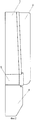
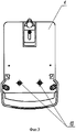
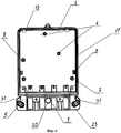
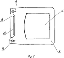
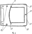
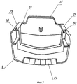
Изобретение иллюстрируется чертежами, где на фиг.1 изображен корпус в сборе; на фиг.2 - корпус сбоку; на фиг.3 - корпус сзади; на фиг.4 - цоколь, на фиг.5 - кожух, на фиг.6 - кожух, вид сзади, на фиг.7 - крышка клеммной колодки, вид сзади.The invention is illustrated by drawings, where in Fig.1 shows a housing assembly; figure 2 - case on the side; figure 3 - housing at the back; figure 4 is a socle, figure 5 is a casing, figure 6 is a casing, rear view, figure 7 is a terminal block cover, rear view.
Данный корпус может быть предназначен для однофазного счетчика со счетным механизмом барабанчикового типа или жидкокристаллического типа.This housing can be designed for a single-phase meter with a drum-type or liquid-crystal type counter.
Корпус прибора состоит из цоколя 1 с элементами крепления счетного механизма и печатной платы с расположенными на ней электронно-измерительными элементами, кожуха 2, колодки 3 с отсеками для зажимов, крышки клеммной колодки 4. В нижней части цоколя выполнен прилив 5 для крепления колодки 3.The housing of the device consists of a
Цоколь 1 позволяет изготавливать счетчики со счетным механизмом барабанчикового типа. Для этого в цоколе имеются две стойки 6 для крепления счетного механизма винтами самонарезающими. Для крепления печатной платы применяются две стойки 7 с бобышками для поддержки печатной платы, одна стойка 8 для крепления винтом и две защелки 9, располагающиеся по бокам от печатной платы. Колодка 3 крепится к цоколю двумя винтами, вставляемыми в отверстия 10 с обратной стороны счетчика, между колодкой и цоколем имеется резиновая уплотнительная прокладка. Цоколь имеет три закладные детали: две - для крепления кожуха, и одну - с обратной стороны цоколя для крепления подвижного металлического уха. По периметру цоколь имеет паз 11 для укладки резиновой уплотнительной прокладки между цоколем и кожухом. Цоколь имеет два внутренних выступа 12 для крепления кожуха в верхней части счетчика.
Кожух 2 счетчика представляет из себя монолитную конструкцию, на которой имеются два отверстия 13 для крепления пломбировочными винтами. Пломбировка осуществляется через специальные канавки 14, предназначенные для закладки пломбировочного проводника и предотвращения несанкционированного откручивания винта. Отверстия 13 имеют внутренние выступы, предотвращающие свободное выпадение винтов. С внутренней стороны кожуха имеются две пустотелые стойки 15 для прижима печатной платы к стойкам с бобышками 7 в цоколе 1. В кожухе выполнено смотровое окно 16, по периметру которого вклеено прозрачное стекло. Прозрачное стекло вклеивается по периметру в окно кожуха на «постамент», что позволяет осуществить надежное герметичное соединение. Также с внутренней стороны кожуха имеются три стойки 17 для крепления щитка счетчика винтами самонарезающими. Для крепления кожуха к цоколю в верхней части кожуха имеются два зацепа 18, взаимодействующих с выступами 12 в цоколе. В нижней части с лицевой стороны кожух имеет фигурное углубление 19 с выступом 20 для стыковки корпуса с крышкой клеммной колодки 4 и для обеспечения степени защиты от окружающей среды класса исполнения IP51 (по ГОСТ 14254-96). По периметру кожух 2 имеет выступ 21 для улучшения герметизации между кожухом, цоколем и клеммной колодкой.The
Колодка 3 счетчика представляет собой монолитную пластмассовою конструкцию, в которой монтируются четыре токовых зажима. Зажимы крепятся за счет установки внатяг и два зажима телеметрического выхода. Колодка имеет три закладных детали - две с обратной стороны в отверстиях 10 для крепления колодки к цоколю и одну - в отверстии 22 на лицевой стороне для крепления крышки клеммной колодки. По линии сопряжения с цоколем и кожухом в колодке имеется паз 23 для укладки двух уплотнительных прокладок (между колодкой и цоколем и между колодкой и кожухом). Каждый зажим имеет два винта крепления проводов подключения и один винт для крепления шунта и перемычки.The
Крышка клеммной колодки 4 имеет в центре одно отверстие 24 для крепления. В глубине отверстия по периметру имеются выступы, которые препятствуют свободному выпадению крепежного винта из крышки. Сверху и снизу отверстия имеются два углубления 25, предназначенные для закладки в них пломбировочного проводника и предотвращения несанкционированного откручивания винта. С внутренней стороны крышки имеется схема подключения счетчика. В нижней части крышки имеется углубление, представляющее из себя тонкую стенку 26, которая может быть выломана при установке счетчика на объекте. В верхней части крышки имеются два паза 27 для обеспечения пропуска пломбировочного проводника от кожуха. Также с внутренней стороны в верхней части крышки имеется фигурный выступ 28 для стыковки с корпусом и обеспечения IP51. По краям фигурного выступа выполнены горизонтальные стенки 29 с прорезями 30, взаимодействующими с вертикальными выступами 31, выполненными на приливе 5 в нижней части цоколя.The terminal block cover 4 has in the center one hole 24 for mounting. There are protrusions in the depth of the perimeter hole that prevent the fixing screw from falling out of the cover. At the top and bottom of the hole there are two recesses 25, intended for laying in them a sealing conductor and preventing unauthorized unscrewing of the screw. On the inside of the lid there is a meter connection diagram. In the lower part of the lid there is a recess, which is a
Корпус счетчика имеет установочные размеры 99×137 мм.The meter case has installation dimensions of 99 × 137 mm.
Такое усовершенствование конструкции корпуса счетчика позволяет сделать его сборку более технологичной, гарантировать полную пыле- и водозащищенность.Such an improvement in the design of the meter body makes it possible to assemble it more technologically, to guarantee complete dust and water resistance.
Claims (9)
Priority Applications (1)
| Application Number | Priority Date | Filing Date | Title |
|---|---|---|---|
| RU2005113215/28A RU2276373C1 (en) | 2005-05-03 | 2005-05-03 | Housing for electricity meter |
Applications Claiming Priority (1)
| Application Number | Priority Date | Filing Date | Title |
|---|---|---|---|
| RU2005113215/28A RU2276373C1 (en) | 2005-05-03 | 2005-05-03 | Housing for electricity meter |
Publications (1)
| Publication Number | Publication Date |
|---|---|
| RU2276373C1 true RU2276373C1 (en) | 2006-05-10 |
Family
ID=36657229
Family Applications (1)
| Application Number | Title | Priority Date | Filing Date |
|---|---|---|---|
| RU2005113215/28A RU2276373C1 (en) | 2005-05-03 | 2005-05-03 | Housing for electricity meter |
Country Status (1)
| Country | Link |
|---|---|
| RU (1) | RU2276373C1 (en) |
Citations (5)
| Publication number | Priority date | Publication date | Assignee | Title |
|---|---|---|---|---|
| SU112268A1 (en) * | 1955-04-04 | 1957-11-30 | Б.Н. Дольницкий | Device for adjusting electrical energy meters |
| SU1456787A1 (en) * | 1985-10-16 | 1989-02-07 | Азербайджанский Научно-Исследовательский Институт Энергетики Им.И.Г.Есьмана | Device for remote measurement of consumption of electric power |
| RU2000576C1 (en) * | 1991-04-29 | 1993-09-07 | н Гурген Степанович Казарь | Casing of induction electricity counter |
| US5450007A (en) * | 1991-09-19 | 1995-09-12 | Ampy Automation-Digilog Limited | Method and apparatus for power measuring |
| RU2206098C2 (en) * | 2000-12-04 | 2003-06-10 | Общество с ограниченной ответственностью "ЭНЭЛЭКО-А" | Electronic device for measuring energy supply |
-
2005
- 2005-05-03 RU RU2005113215/28A patent/RU2276373C1/en not_active IP Right Cessation
Patent Citations (5)
| Publication number | Priority date | Publication date | Assignee | Title |
|---|---|---|---|---|
| SU112268A1 (en) * | 1955-04-04 | 1957-11-30 | Б.Н. Дольницкий | Device for adjusting electrical energy meters |
| SU1456787A1 (en) * | 1985-10-16 | 1989-02-07 | Азербайджанский Научно-Исследовательский Институт Энергетики Им.И.Г.Есьмана | Device for remote measurement of consumption of electric power |
| RU2000576C1 (en) * | 1991-04-29 | 1993-09-07 | н Гурген Степанович Казарь | Casing of induction electricity counter |
| US5450007A (en) * | 1991-09-19 | 1995-09-12 | Ampy Automation-Digilog Limited | Method and apparatus for power measuring |
| RU2206098C2 (en) * | 2000-12-04 | 2003-06-10 | Общество с ограниченной ответственностью "ЭНЭЛЭКО-А" | Electronic device for measuring energy supply |
Non-Patent Citations (1)
| Title |
|---|
| Илюкович А.М. Электрические счетчики. М-Л, Энергия, 1963, с.290. Алукер Ш.М. Электроизмерительные приборы. Учеб. пособие для ПТУ. Высш. шк., 1976, с.72-75. * |
Similar Documents
| Publication | Publication Date | Title |
|---|---|---|
| RU167008U1 (en) | ELECTRIC ENERGY METER HOUSING | |
| KR100807364B1 (en) | Electronic electricity meter | |
| RU89712U1 (en) | ELECTRIC ENERGY METER CASE | |
| RU2276373C1 (en) | Housing for electricity meter | |
| CN215343548U (en) | A household electrical distribution box that is easy to maintain | |
| RU209242U1 (en) | MULTIFUNCTIONAL MULTI-TARIFF METER WITH REPLACEABLE UNIFIED MODULES | |
| RU73085U1 (en) | ELECTRIC ENERGY METER CASE | |
| RU49277U1 (en) | ELECTRIC ENERGY METER CASE | |
| CN211209025U (en) | Modular block terminal convenient to installation is dismantled | |
| RU110496U1 (en) | ELECTRIC ENERGY METER | |
| RU2282200C1 (en) | Body of electricity meter | |
| RU182808U1 (en) | ELECTRIC ENERGY METER | |
| RU111305U1 (en) | ELECTRIC ENERGY METER | |
| RU48642U1 (en) | ELECTRIC ENERGY METER CASE | |
| CN213091747U (en) | A multimeter with a buckled sheath | |
| RU2282859C1 (en) | Case of electric energy metering device | |
| RU46588U1 (en) | ELECTRICITY METER CASE | |
| RU188746U1 (en) | Electric energy meter case | |
| CN215910543U (en) | Electric meter box capable of preventing strong magnetic interference | |
| CN214040208U (en) | Water meter internet module box | |
| RU73084U1 (en) | ELECTRIC ENERGY METER CASE | |
| RU52638U1 (en) | ELECTRIC ENERGY METER | |
| RU56647U1 (en) | ELECTRICAL INSTRUMENT DESIGN | |
| RU38084U1 (en) | ELECTRICITY DISTRIBUTION PANEL IN RESIDENTIAL AND PUBLIC BUILDINGS | |
| RU185210U1 (en) | Electric energy meter housing |
Legal Events
| Date | Code | Title | Description |
|---|---|---|---|
| MM4A | The patent is invalid due to non-payment of fees |
Effective date: 20070504 |