RU2270472C2 - Method for controlling oils compounding process with several quality parameters and system for realization of said method - Google Patents
Method for controlling oils compounding process with several quality parameters and system for realization of said method Download PDFInfo
- Publication number
- RU2270472C2 RU2270472C2 RU2004100877/06A RU2004100877A RU2270472C2 RU 2270472 C2 RU2270472 C2 RU 2270472C2 RU 2004100877/06 A RU2004100877/06 A RU 2004100877/06A RU 2004100877 A RU2004100877 A RU 2004100877A RU 2270472 C2 RU2270472 C2 RU 2270472C2
- Authority
- RU
- Russia
- Prior art keywords
- oil
- flow
- content
- transported
- density
- Prior art date
Links
Abstract
Description
Заявленная группа изобретений относится к средствам автоматизации процессов транспортирования нефти по различным трубопроводам с разным качеством нефти и объединения потоков нефти с контролированием в смеси нефти показателей ее качества.The claimed group of inventions relates to means for automating the processes of oil transportation through various pipelines with different oil quality and combining oil flows with monitoring its quality indicators in an oil mixture.
Наиболее близкими к заявленной группе изобретений является способ управления процессом компаундирования нефти по нескольким параметрам качества, по содержанию серы, и/или по плотности нефти, и/или по содержанию хлористых солей, и/или по содержанию воды, а также по расходу продуктов и система для его осуществления (Свидетельство на полезную модель РФ №28930, опубл. 20 апреля 2003 г.).Closest to the claimed group of inventions is a method of controlling the compounding of oil by several quality parameters, by sulfur content, and / or by oil density, and / or by the content of chloride salts, and / or by the water content, as well as by the consumption of products and the system for its implementation (Certificate for utility model of the Russian Federation No. 28930, publ. April 20, 2003).
В известном способе и системе обеспечивается контроль и ведение регулирования компаундирования нефти по нескольким параметрам качества.In the known method and system provides control and regulation of compounding of oil for several quality parameters.
Известный способ управления процессом компаундирования нефти заключается в том, что измеряют расход и, по меньшей мере, один из показателей качества (плотность, и/или содержание серы, и/или содержание хлористых солей, и/или содержание воды) каждого из транспортируемых потоков нефти и смешанного потока нефти, определяют соотношение показателей качества в каждом из транспортируемых потоков и смешанного потока и соотношение расходов каждого из транспортируемых потоков и смешанного потока и сравнивают их с заданными, и если соотношения расходов находятся в пределах заданных значений, а соотношения показателей качества не соответствуют заданным, изменяют расход соответствующего транспортируемого потока нефти до достижения заданного значения соотношения показателей качества.A known method for controlling the oil compounding process is that the flow rate and at least one of the quality indicators (density and / or sulfur content and / or chloride content and / or water content) of each of the transported oil streams are measured and mixed flow of oil, determine the ratio of quality indicators in each of the transported flows and mixed flow and the ratio of the costs of each of the transported flows and mixed flow and compare them with the given, and if the ratio of odov are within specified values, and the ratio of quality parameters do not match, changing the flow rate corresponding to the conveyed oil flow to achieve the desired ratio values quality indicators.
Известная система управления процессом компаундирования нефти, содержащая, по крайней мере, два нефтепровода, предназначенных для транспортирования потоков нефти, и нефтепровод, предназначенный для смешанного потока нефти, заслонки, установленные в нефтепроводах и предназначенные для регулирования соответствующих потоков нефти, измерители расхода нефти, а также измерители плотности нефти, и/или измерители содержания серы в нефти, и/или измерители содержания хлористых солей в нефти, и/или измерители содержания воды в нефти, предназначенные для измерения указанных параметров нефти в соответствующих потоках нефти, дополнительно содержит измеритель расхода нефти, а также измеритель плотности нефти, и/или измеритель содержания серы в нефти, и/или измеритель содержания хлористых солей в нефти, и/или измеритель содержания воды в нефти, предназначенные для измерения указанных параметров нефти в смешанном потоке, вычислитель коэффициентов соотношения величины расхода нефти в каждом потоке к величине расхода нефти в смешанном потоке, вычислитель коэффициентов соотношения величины плотности нефти в каждом потоке к величине плотности нефти в смешанном потоке, и/или вычислитель коэффициентов соотношения величины содержания серы в нефти в каждом потоке к величине содержания серы в нефти в смешанном потоке, и/или вычислитель коэффициентов соотношения величины содержания хлористых солей в нефти в каждом потоке к величине содержания хлористых солей в нефти в смешанном потоке, и/или вычислитель коэффициентов соотношения величины содержания воды в нефти в каждом потоке к величине содержания воды в нефти в смешанном потоке, входы каждого из указанных вычислителей связаны с выходами соответствующих измерителей, а выходы соединены с соответствующими входами микропроцессора, предназначенного для сравнения измеренных и вычисленных параметров с заданными и формирования сигналов регулирования положения заслонок в соответствующих потоках по результатам сравнения.A known oil compounding process control system comprising at least two oil pipelines for transporting oil flows, and an oil pipeline for a mixed oil flow, dampers installed in the oil pipelines and for regulating respective oil flows, oil flow meters, and meters of oil density, and / or meters of sulfur content in oil, and / or meters of chloride salts in oil, and / or meters of water content in oil, intended data for measuring these parameters of oil in the respective oil flows, further comprises an oil flow meter, as well as an oil density meter, and / or a sulfur content meter in the oil, and / or a salt chloride content meter in the oil, and / or a water content meter in the oil designed to measure the specified parameters of oil in a mixed stream, a calculator of the coefficients of the ratio of the amount of oil consumption in each stream to the value of the oil flow in the mixed stream, the calculator of the ratio the values of the density of oil in each stream to the value of the density of oil in the mixed stream, and / or the calculator of the coefficients of the ratio of the sulfur content in oil in each stream to the value of the sulfur content of the oil in the mixed stream, and / or the calculator of the coefficients of the ratio of the content of chloride salts in oil in each stream to the value of the content of chloride salts in oil in the mixed stream, and / or a calculator of the coefficients of the ratio of the amount of water in oil in each stream to the value of the water content in oil in the mixture SG stream, the inputs of each of these calculators are connected to the outputs of the respective measuring devices and the outputs are connected to respective inputs of the microprocessor for comparing the measured and calculated parameters with predetermined positions and forming flaps regulation signals in respective streams from the comparison results.
Однако известные способ и система регулирования компаундирования могут эффективно работать, когда на каждом потоке установлены средства измерения показателей качества, например, измерителей содержания серы, плотности, хлористых солей, воды. Указанные измерители показателей качества - дорогостоящее оборудование, поэтому экономически целесообразно ограничить количество некоторых измерителей показателей качества во входящих на компаундирование потоках и в то же время обеспечить эффективное компаундирование смешиваемых потоков.However, the known compounding control method and system can work efficiently when means of measuring quality indicators, for example, measuring sulfur content, density, chloride salts, water, are installed on each stream. These quality indicators are expensive equipment; therefore, it is economically feasible to limit the number of some quality indicators in the flows entering compounding and at the same time to ensure effective compounding of mixed flows.
Техническим результатом заявленного изобретения является упрощение процесса и системы регулирования процесса компаундирования нефти по нескольким параметрам качества, поскольку оно позволяет обойтись без установки во входящих потоках некоторых дорогостоящих измерителей качества, например измерителя содержания серы, измерителя содержания воды.The technical result of the claimed invention is to simplify the process and the system for regulating the oil compounding process according to several quality parameters, since it can do without installing some expensive quality meters in the input streams, for example, a sulfur content meter, a water content meter.
Технический результат достигается тем, что в способе управления процессом компаундирования нефти, заключающемся в том, что измеряют значения расхода транспортируемых потоков нефти и расход смешанного потока нефти, определяют содержание в транспортируемых потоках и в смешанном потоке нефти серы и/или воды, определяют соотношения указанных содержаний в каждом из транспортируемых потоков и в смешанном потоке и соотношения расходов каждого из транспортируемых потоков и смешанного потока и сравнивают эти соотношения с заданными значениями, при соответствии всех соотношений расходов с заданными значениями и при отклонении соотношения указанных содержаний, по меньшей мере, для одного транспортируемого потока регулируют расход нефти соответствующего потока, определение содержания серы и/или воды в каждом из транспортируемых потоков осуществляют путем измерения плотности нефти в соответствующем потоке с учетом корреляционной зависимости между плотностью и содержанием соответствующего компонента.The technical result is achieved by the fact that in the method of controlling the process of compounding the oil, which consists in measuring the flow rate of the transported oil streams and the flow rate of the mixed oil stream, determining the content of sulfur and / or water in the transported streams and in the mixed stream of oil, determining the ratios of these contents in each of the transported streams and in the mixed stream and the ratio of the flow rates of each of the transported streams and the mixed stream and compare these ratios with the given values mi, in accordance with all flow ratios with specified values and with a deviation in the ratio of the indicated contents for at least one transported stream, the oil flow rate of the corresponding stream is regulated, the sulfur and / or water content in each of the transported streams is determined by measuring the oil density in the corresponding flow taking into account the correlation between the density and the content of the corresponding component.
Технический результат достигается также тем, что система управления процессом компаундирования нефти, содержащая установленные в каждом из нефтепроводов для транспортирования нефти измеритель расхода, измеритель плотности нефти и средство регулирования расхода нефти, установленные в нефтепроводе для смешанного потока измеритель расхода нефти, и измеритель содержания серы и/или измеритель содержания воды, а также вычислитель коэффициентов соотношения расходов нефти в каждом транспортируемом потоке и в смешанном потоке, вычислитель коэффициентов соотношения содержаний серы в нефти в каждом транспортируемом потоке и в смешанном потоке и/или вычислитель коэффициентов соотношения содержаний воды в нефти в каждом транспортируемом потоке и в смешанном потоке, входы первого из указанных вычислителей связаны с измерителями расхода, а выходы каждого из указанных вычислителей соединены с соответствующими входами блока сравнения, выходы которого связаны со средствами регулирования расхода нефти, снабжена вычислителем содержания серы в нефти и/или вычислителем содержания воды в нефти, выполненным с возможностью расчета содержания соответствующего компонента с учетом корреляционной зависимости между плотностью нефти и содержанием этого компонента, входы каждого из этих вычислителей связаны с соответствующими измерителями плотности нефти транспортируемых потоков, а выходы соединены с соответствующими входами соответствующего вычислителя коэффициентов соотношений.The technical result is also achieved by the fact that the oil compounding process control system, comprising a flow meter, an oil density meter and an oil flow control means installed in each of the oil pipelines for transporting oil, an oil flow meter and a sulfur content meter and / or a meter of water content, as well as a calculator of the coefficients of the ratio of oil consumption in each transported stream and in the mixed stream, the calculator the coefficients of the ratio of sulfur contents in oil in each transported stream and in the mixed stream and / or a calculator of the coefficients of the ratio of water contents in oil in each transported stream and in the mixed stream, the inputs of the first of these calculators are connected to flow meters, and the outputs of each of these calculators are connected with the corresponding inputs of the comparison unit, the outputs of which are connected with means for regulating oil flow, is equipped with a calculator of sulfur content in oil and / or a calculator containing water in oil, made with the possibility of calculating the content of the corresponding component, taking into account the correlation between the oil density and the content of this component, the inputs of each of these calculators are connected to the corresponding oil density meters of the transported flows, and the outputs are connected to the corresponding inputs of the corresponding calculator of the ratio ratios.
В заявленной системе исключение установки вышеназванных измерителей качества во входящих потоках достигается за счет использования корреляционной зависимости между содержанием серы и плотностью, корреляционной зависимости между содержанием воды и плотностью при регулировании компаундирования. На практике наблюдается тенденция, что при увеличении содержания серы в нефти увеличивается значение плотности, при этом необходимо иметь в виду то обстоятельство, что увеличение содержания воды также приводит к увеличению плотности.In the claimed system, the exclusion of the installation of the above quality meters in the incoming flows is achieved by using the correlation between the sulfur content and density, the correlation between the water content and density when adjusting the compounding. In practice, there is a tendency that with increasing sulfur content in oil, the density value increases, it must be borne in mind that the increase in water content also leads to an increase in density.
Корреляционную зависимость между значениями содержания серы и плотности можно установить из статистических данных диспетчерской службы или по экспериментальным данным за определенный период времени (месяц, квартал и т.д.). Например, в таблице 1 приведены значения содержания серы и плотности на приемосдаточном пункте (ПСП) «Юргамыш» по данным записи в оперативном журнале диспетчерской службы за январь месяц 2001 г.The correlation between the values of sulfur content and density can be established from the statistical data of the dispatching service or from experimental data for a certain period of time (month, quarter, etc.). For example, table 1 shows the values of sulfur content and density at the acceptance point (PS) "Yurgamysh" according to the record in the operational journal of the dispatch service for January 2001.

Для установления зависимости между значениями серы и плотности используем теорию линейной регрессии [1].To establish the relationship between the values of sulfur and density, we use the theory of linear regression [1].
![]()
![]()
где - ![]()
![]()
ρ - плотность;ρ is the density;
b0, b1 - коэффициенты определяются из экспериментальных данных.b 0 , b 1 - the coefficients are determined from experimental data.
Используя метод наименьших квадратов, получаем оцениваемое уравнение (2) регрессииUsing the least squares method, we obtain the estimated regression equation (2)
![]()
![]()
где ![]()
![]()
![]()
![]()

Используя данные табл.1 и вышеприведенные соотношения (2) и (3), получим уравнение регрессии для описания зависимости между содержанием серы по УУН №17 ЛПДС «Юргамыш»Using the data of Table 1 and the above relations (2) and (3), we obtain the regression equation to describe the relationship between the sulfur content according to УУН No. 17 of the Yurgamysh LPDS
![]()
![]()
Промежуточные расчеты приведены в таблице 2.Interim calculations are shown in table 2.
Плотность при 20°С - среднесуточное значение плотности, приведенное к 20°С, определенное из среднеарифметических показаний автоматического плотномера, зарегистрированных через каждые два часа или по лабораторному анализу объединенной суточной пробы, приведенной к 20°С.Density at 20 ° С - daily average density value reduced to 20 ° С, determined from the arithmetic average of the automatic densitometer recorded every two hours or from laboratory analysis of the combined daily sample reduced to 20 ° С.
Содержание S - среднесуточное массовое содержание серы, среднеарифметическое значение содержания серы в вахтовых пробах, определенных в лаборатории лабораторным прибором или анализатором содержания серы на потоке.Content S - daily average mass sulfur content, arithmetic mean value of sulfur content in rotational samples determined in the laboratory by a laboratory device or flow sulfur analyzer.
Вычислим по формуле (4) прогнозное значение содержания серы при плотности ρ=853,9 кг/м3 We calculate by the formula (4) the forecast value of the sulfur content at a density ρ = 853.9 kg / m 3
![]()
![]()
По таблице 1 значению плотности ρ=853,9 кг/м3 соответствует значение серы 1,09%.According to table 1, the density value ρ = 853.9 kg / m 3 corresponds to a sulfur value of 1.09%.
Оценка расчетных данных по полученному уравнению (4) от экспериментальных значений показывает, что расхождение между ними не превышает 1,6%, что вполне приемлемо для использования уравнения регрессии на практике при компаундировании. Как видно из таблицы 1, содержание воды в нефти по абсолютной величине составляет небольшую величину (в основном, от 0,15 до 0,28%), и поэтому можно не учитывать влияние на изменение плотности изменение содержания воды.Evaluation of the calculated data by the obtained equation (4) from the experimental values shows that the difference between them does not exceed 1.6%, which is quite acceptable for using the regression equation in practice when compounding. As can be seen from table 1, the water content in oil in absolute value is a small amount (mainly from 0.15 to 0.28%), and therefore we can not take into account the effect on the change in density of the change in water content.
По степени подготовки нефти разделяются на группы по ГОСТ Р 51858-2002 «Нефть. Общие технические условия». Массовая доля содержания воды в нефти по 3 группе регламентируется не более 1%.According to the degree of oil preparation, they are divided into groups according to GOST R 51858-2002 “Oil. General specifications. " The mass fraction of water content in oil for group 3 is regulated by no more than 1%.
Однако в некоторых случаях при трубопроводном транспорте при низких скоростях перекачки может выделяться вода из потока нефти и скапливаться на пониженных участках рельефа трассы. А при увеличении скорости перекачки скопления воды могут выноситься потоком нефти, что приводит к обводнению нефти выше допустимых значений. Также при вводе в эксплуатацию новых участков трубопроводов после строительства или капитального ремонта с заменой трубы производится гидравлическое испытание на прочность и герметичность. На практике наблюдаются случаи, когда часть оставшейся опрессовочной воды после гидравлических испытаний указанных участков трубопроводов приводит к обводнению нефти при вводе их в эксплуатацию. Как правило, в таких случаях массовая доля воды в нефти может достигать до 3%.However, in some cases, when pipelines transport at low pumping speeds, water can be released from the oil stream and accumulate in lower sections of the route relief. And with an increase in the pumping speed, water accumulations can be carried away by the oil flow, which leads to oil flooding above the permissible values. Also, when commissioning new sections of pipelines after construction or major repairs with the replacement of the pipe, a hydraulic test for strength and tightness is performed. In practice, there are cases when part of the remaining pressure water after hydraulic tests of these sections of the pipelines leads to water flooding when they are put into operation. As a rule, in such cases, the mass fraction of water in oil can reach up to 3%.
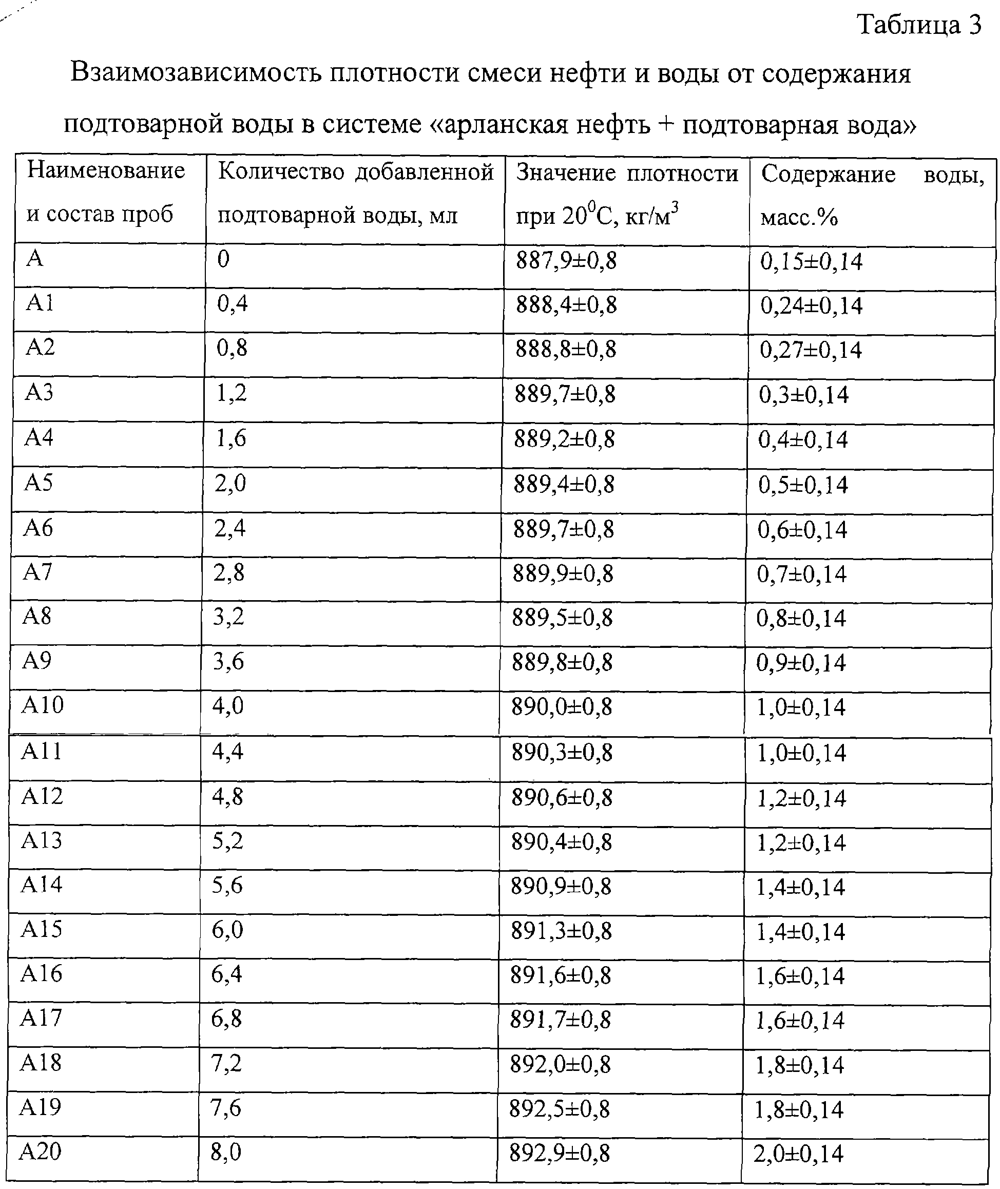
Проводили исследования взаимозависимости плотности смеси нефти и воды от содержания воды при постоянных значениях содержания остальных параметров качества (содержания серы, механических примесей, хлористых солей). В пробу нефти с известным содержанием параметров качества добавлялась пресная вода и вода подтоварная, содержание воды изменялось до 2% и при этом проводилось измерение значения плотности смеси нефти. В таблице 3 приведены результаты экспериментальных данных, когда в арланскую нефть добавлялась подтоварная вода.Studies were conducted on the interdependence of the density of the mixture of oil and water on the water content at constant values of the remaining quality parameters (sulfur content, solids, chloride salts). Fresh water and bottom water were added to the oil sample with a known content of quality parameters, the water content was changed to 2% and the density of the oil mixture was measured. Table 3 shows the results of experimental data when commercial water was added to Arlan oil.
Эмпирическую зависимость между значениями содержания воды и плотности также можно определить на основании опытных данных, используя теорию линейной регрессии [1], уравнение имеет вид:The empirical relationship between the values of water content and density can also be determined on the basis of experimental data using the theory of linear regression [1], the equation has the form:
![]()
![]()
После обработки опытных данных, приведенных в таблице 3, по формулам (2), (3) получим эмпирическую зависимость содержания воды в нефти от значения плотности для данного конкретного случая.After processing the experimental data shown in table 3, using formulas (2), (3), we obtain the empirical dependence of the water content in oil on the density value for this particular case.
![]()
![]()
По данным эксперимента, приведенным в таблице 3, значению плотности 891,3 кг/м3 соответствует содержание воды 1,4%. Расчетное значение содержания воды по эмпирической формуле (6) составляет 1,4%. Для плотности 892,9 кг/м3 соответствует значение содержания воды по экспериментальным данным 2,0%, а по формуле (6) - 2,03%. Расхождение составляет 1,5%.According to the experiment, shown in table 3, the density value of 891.3 kg / m 3 corresponds to a water content of 1.4%. The calculated value of the water content according to the empirical formula (6) is 1.4%. For a density of 892.9 kg / m 3, the value of water content corresponds to 2.0% according to experimental data, and 2.03% according to formula (6). The discrepancy is 1.5%.
Изобретение поясняется чертежом, где приведена функциональная схема заявленной системы.The invention is illustrated in the drawing, which shows a functional diagram of the claimed system.
Заявленная система отличается от известной системы возможностью работы при отсутствии дорогостоящего оборудования измерителя содержания серы и/или измерителя содержания воды, дополнительно включает вычислитель содержания серы и/или вычислитель содержания воды.The claimed system differs from the known system in the ability to work in the absence of expensive equipment for a sulfur content meter and / or a water content meter, further includes a sulfur content calculator and / or a water content calculator.
Система содержит нефтепроводы 1-3, емкость 4 для смешения, предназначенную для смешивания потоков нефти и передачи смешанного потока в соединенный с ней нефтепровод 5, установленные в нефтепроводах 1-3 измерители 61-63 расхода нефти, измерители 71-73 плотности. В нефтепроводах 1-3 могут также быть установлены измерители 91-93 содержания хлористых солей, а также установлены заслонки 101-103. Насосный агрегат 12 с системой автоматического регулирования (CAP) 13 установлен в нефтепроводе 5 смешанного потока нефти, в котором также установлены измеритель 6 расхода нефти смешанного потока нефти, измеритель 7 плотности смешанного потока, измеритель 8 содержания серы в смешанном потоке, измеритель 9 содержания хлористых солей в смешанном потоке, измеритель 11 содержания воды в смешанном потоке, связанные с соответствующими измерителями 61-63 и 6 вычислитель 14 коэффициентов соотношения расхода KQ1, KQ2, KQ3 в каждом потоке по отношению к величине расхода нефти в смешанном потоке нефтепровода 5, связанный с соответствующими измерителями 71-73 и 7 вычислитель 15 коэффициентов соотношения величины плотности Kp1, Кр2, Кр3 в каждом потоке по отношению к величине плотности нефти в смешанном потоке нефтепровода 5, связанный с выходом соответствующего вычислителя 22 содержания серы и измерителя 8 вычислитель 16 коэффициентов соотношения содержания серы в каждом из потоков к величине содержания серы в смешанном потоке, связанный с соответствующими измерителями 91-93 и 9 вычислитель 17 коэффициентов соотношения хлористых солей в каждом из потоков к величине содержания хлористый солей в смешанном потоке, связанный с выходом соответствующего вычислителя 23 содержания воды измерителя 11 вычислитель 18 коэффициентов соотношения содержания воды в каждом из потоков к величине содержания воды в смешанном потоке, каждый из указанных вычислителей связан с соответствующими входами блока сравнения - микропроцессора 20 (с шиной данных микропроцессора), предназначенного для сравнения вышеуказанных измеренных и вычисленных параметров с заданными и между собой по алгоритмам, приведенным ниже, и формирования сигналов регулирования положения заслонок 101-103, связанных с выходами микропроцессора 20 по результатам сравнения.The system contains oil pipelines 1-3, a mixing tank 4, designed to mix oil flows and transfer the mixed stream to the oil pipeline 5 connected to it, 1-3 meters 6 1 -6 3 oil flow meters installed in the pipelines, 7 1 -7 3 density meters . In pipelines 1-3, gauges 9 1 -9 3 of the content of chloride salts can also be installed, and also shutters 10 1 -10 3 can be installed. A pump unit 12 with an automatic control system (CAP) 13 is installed in the mixed oil flow pipeline 5, which also has a mixed oil flow meter 6, a mixed flow density meter 7, a mixed flow sulfur meter 8, and a chloride salt meter 9 in the mixed stream, the meter 11 of the water content in the mixed stream associated with the corresponding meters 6 1 -6 3 and 6 calculator 14 coefficients of the ratio of the flow rate KQ 1 , KQ 2 , KQ 3 in each stream in relation to led the flow rate of oil in the mixed flow of oil pipeline 5, associated with the corresponding meters 7 1 -7 3 and 7 calculator 15 of the coefficients of the ratio of the density values Kp 1 , Kr 2 , Kr 3 in each stream in relation to the density of oil in the mixed flow of the pipeline 5, associated a yield calculator 22, the corresponding sulfur and meter 16 coefficients calculator 8 ratio of sulfur in each of the flows to the value of the sulfur content in the mixed stream that is associated with the respective calipers September 1 -9 3 and 9 calculator 17 koe factors of the ratio of chloride salts in each of the streams to the value of the chloride content of salts in the mixed stream associated with the output of the corresponding calculator 23 of the water content of the meter 11 calculator 18 coefficients of the ratio of the water content in each of the streams to the value of the water content in the mixed stream, each of these calculators is connected with the corresponding inputs of the comparison unit - microprocessor 20 (with the data bus of the microprocessor), designed to compare the above measured and calculated parameters with the set and among themselves according to the algorithms below, and the formation of signals for regulating the position of the shutters 10 1 -10 3 associated with the outputs of the microprocessor 20 according to the comparison results.
Способ управления процессом компаундирования осуществляется следующим образом.The method of controlling the compounding process is as follows.
Пусть необходимо осуществить смешение потоков нефти различного качества, поступающих по нескольким нефтепроводам 1-3, отличающихся по параметрам плотности (Р), и/или содержанию хлористых солей (С1), и/или содержанию серы (S), и/или воды (В).Let it be necessary to mix the oil flows of different quality coming through several oil pipelines 1-3, differing in density parameters (P), and / or the content of chloride salts (C1), and / or the content of sulfur (S), and / or water (B )
Индексы в приведенных ниже уравнениях предназначены для указания принадлежности номеру потока в соответствующем трубопроводе 1, 2, 3 или смешанному потоку, Q - показатель расхода.The indices in the equations below are intended to indicate belonging to the flow number in the corresponding pipe 1, 2, 3 or mixed flow, Q - flow rate.
Пусть требуется осуществление контроля и ведение регулирования компаундирования по нескольким параметрам качества, например, по содержанию серы, и/или по плотности, и/или по содержанию хлористых солей, и/или содержанию воды.Let control and compounding regulation be required for several quality parameters, for example, for sulfur content, and / or for density, and / or for the content of chloride salts, and / or water content.
При смешивании потоков нефти из разных нефтепроводов в нефтепроводе 15 параметры качества подчиняются закону аддитивностиWhen mixing oil flows from different oil pipelines in oil pipeline 15, the quality parameters obey the additivity law
![]()
![]()
Рсм - плотность, а Qсм - расход смешанной нефти в нефтепроводе 10. Поделив правую и левую части уравнения на Qсм, имеемP cm is the density, and Q cm is the consumption of mixed oil in the oil pipeline 10. Dividing the right and left sides of the equation by Q cm , we have
![]()
![]()
При этом очевидно, что Q1+Q2+Q3=Qсм, а коэффициенты KQ1, KQ2, KQ3 - соотношение расходов по нефтепроводам потоков 1, 2, 3 к общему расходу Qсм в смешанном потоке нефтепровода 15, полученные в результате деления величин Q1, Q2, Q3 на величину Qсм соответственно.It is obvious that Q 1 + Q 2 + Q 3 = Q cm , and the coefficients K Q1 , K Q2 , K Q3 are the ratio of the costs of the oil pipelines of flows 1, 2, 3 to the total flow Q cm in the mixed flow of the oil pipeline 15, obtained as a result of dividing the quantities Q 1 , Q 2 , Q 3 by the value of Q cm, respectively.
Аналогично можно получить уравнение по содержанию серыSimilarly, you can get the equation for sulfur content
![]()
![]()
при этом, поделив правую и левую части на Qсм, получаемwhile dividing the right and left parts by Q cm , we obtain
![]()
![]()
Таким образом, в формулах участвует соотношение расходов KQ1, KQ2, KQ3, в общем случае KQi, где i=1÷n (число нефтепроводов или число смешиваемых потоков).Thus, the ratio of costs K Q1 , K Q2 , K Q3 , in the general case K Qi , where i = 1 ÷ n (the number of pipelines or the number of mixed flows) is involved in the formulas.
Исходя из соотношения вышеуказанных показателей KQ для автоматического регулирования задают эти соотношения расходов, например, исходя из плановых объемов; в зависимости от содержания серы или плотности нефти и т.п. Т.о., измеряя расход Q в каждом потоке и в потоке смеси нефтепровода 15 с измерителей 6 и определяя в вычислителе 14 KQ как отношение расхода Qi/Qсм, получают KQ для каждого потока. Кроме того, в вычислителе 14 осуществляют суммирование величин Q1+Q2+Q3 для получения величины Qсм, полученные величины пересылают в соответствующий элемент памяти 21 для использования при работе микропроцессора 20.Based on the ratio of the above indicators K Q for automatic regulation, these cost ratios are set, for example, based on planned volumes; depending on sulfur content or oil density, etc. Thus, by measuring the flow rate Q in each stream and in the flow of the mixture of oil pipeline 15 from meters 6 and determining in the calculator 14 K Q as the ratio of the flow rate Q i / Q cm , K Q is obtained for each stream. In addition, in the calculator 14 summarize the values of Q 1 + Q 2 + Q 3 to obtain the Q cm value, the obtained values are sent to the corresponding memory element 21 for use when operating the microprocessor 20.
В известной системе, а также и в заявленной системе поддержание заданных параметров при компаундировании потоков нефти для случая регулирования по показателю плотности не отличаются и осуществляются следующим образом.In the known system, as well as in the claimed system, the maintenance of the specified parameters when compounding the oil flows for the case of regulation in terms of density do not differ and are carried out as follows.
Устанавливают в каждом нефтепроводе 1-3 каждого потока измерители 71-73 плотности. При этом для регулирования по плотности уравнение (7) запишем в виде:Install in each pipeline 1-3 of each flow meters 7 1 -7 3 density. Moreover, to control the density, we write equation (7) in the form:
![]()
![]()
где KP1, KP2, КP3 - соотношение плотностей в нефтепроводах 41-43 к плотности смеси в нефтепроводе 5, полученное как отношение P1/Рсм, Р2/Рсм, P3/Pсм.where K P1 , K P2 , K P3 is the ratio of the densities in the oil pipelines 4 1 -4 3 to the mixture density in the oil pipeline 5, obtained as the ratio of P 1 / P cm , P 2 / P cm , P 3 / P cm .
Осуществляют определение этих коэффициентов в вычислителе 15 и запоминают полученные величины в элементе памяти 212.These coefficients are determined in the calculator 15 and the obtained values are stored in the memory element 21 2 .
Микропроцессор 20 сравнивает величины KQ1, KQ2, KQ3 с заданными. Пусть микропроцессор 20 определил, что соотношение расходов не изменилось, т.е. KQ1, KQ2 и KQ3 находятся в диапазоне заданных значений. Однако он выявил изменение соотношения плотностей, полученных в вычислителе 15, от заданных значений КP1зад, КP2зад, КP3зад. Микропроцессор осуществляет сравнение полученных КP из вычислителя 15 и плотностей из измерителей 7 с заданными значениями. При этом пусть выявлено, что Рсм>Рзад, тогда и выявляется, что КPi>КPi-зад и микропроцессор 20 формирует сигнал регулирования данного потока путем прикрытия заслонки 10i системы автоматического регулирования (задвижки), т.е. изменяя соотношение расхода до тех пор, пока Рсм=Pзад.The microprocessor 20 compares the values of K Q1 , K Q2 , K Q3 with the set. Let the microprocessor 20 determine that the cost ratio has not changed, i.e. K Q1 , K Q2 and K Q3 are in the range of set values. However, he revealed a change in the ratio of the densities obtained in the calculator 15 from the given values of K P1ad , K P2ad , K P3ad . The microprocessor compares the obtained K P from the calculator 15 and the densities from the meters 7 with the given values. In this case, let it be revealed that P cm > P back , then it will be revealed that K Pi > K Pi-back and microprocessor 20 generates a control signal for this stream by covering the shutter 10 i of the automatic control system (shutter), i.e. changing the flow ratio until P cm = P ass .
Указанное соотношение расходов запоминается в элементе памяти 21.The specified ratio of expenses is stored in the memory element 21.
Рассмотрим вариант, когда предыдущее соотношение расходов не изменилось, т.е. микропроцессор 20 определил, что указанное соотношение расходов находится в пределах заданных значений, однако он выявил, что Рсм<Рзад, и что КPi<КPi-зад, тогда микропроцессор 20 формирует сигнал на регулирование по данному потоку путем приоткрывания заслонки 10i CAP, т.е. изменяя соотношение расходов.Consider the option when the previous cost ratio has not changed, i.e. the microprocessor 20 determined that the indicated flow ratio is within the specified values, however, it revealed that P cm <P back , and that K Pi <K Pi-back , then the microprocessor 20 generates a control signal for this flow by opening the valve 10 i CAP, i.e. changing the ratio of costs.
Пусть микропроцессор 20 выявил, что соотношение плотностей KP1≤KP1-зад; КP2≤КP2-зад; КP3≤КP3-зад, а Рсм>Рзад. Определяют соотношение расходов в вычислителе 14, и микропроцессор 20 контролирует соотношение расхода при выявлении KQi>KQi-зад, микропроцессор 20 формирует сигнал регулирования на прикрытие соответствующей заслонки 10i на потоке i (i=1, 2, 3), т.е. уменьшая соотношение расходов. Наоборот, если выявляется KQi<KQi-зад и имеется запас качества Рсм<Рсм-зад, то микропроцессор формирует сигнал на приоткрывание заслонки 10i и регулирование проводится до тех пор, пока Рсм≈Рсм-зад.Let the microprocessor 20 revealed that the density ratio K P1 ≤K P1-back ; To P2 ≤ To P2-back ; To P3 ≤ To P3-back , and P cm > P back . The flow ratio is determined in the calculator 14, and the microprocessor 20 controls the flow ratio when K Qi > K Qi is detected, the microprocessor 20 generates a control signal to cover the corresponding shutter 10 i on the flow i (i = 1, 2, 3), i.e. . reducing the cost ratio. Conversely, if K Qi <K Qi-back is detected and there is a quality margin P cm <P cm-back , then the microprocessor generates a signal to open the shutter 10 i and regulation is carried out until P cm ≈ P cm-back .
Рассмотрим процесс компаундирования при регулировании по параметру серы.Consider the compounding process when controlling for the sulfur parameter.
В известной системе на всех потоках (нефтепроводы 1-3) предусмотрена установка измерителей 81-83 содержания серы. Регулирование осуществляют аналогично регулированию по параметру плотности. При этом применяют формулу (9).In the known system on all flows (oil pipelines 1-3) provides the installation of meters 8 1 -8 3 sulfur content. Regulation is carried out similarly to regulation by the density parameter. In this case, formula (9) is used.
![]()
![]()
или, поделив все части уравнения на Sсм, получим:or, dividing all parts of the equation by S cm , we get:
![]()
![]()
Таким образом, установив в каждом из потоков нефти (нефтепроводы 11-33 и нефтепровод 5) измерители 8, 81-83 содержания серы, соединив измерители 81-83 и 8 с вычислителем 16, получают соотношения содержания серы в каждом потоке по отношению к смешанному потоку, т.е. KS1=S1/Sсм, KS2=S2/Sсм и KS3=S3/Sсм. Выходы вычислителя 16 связаны с блоком 20 сравнения (микропроцессором) для осуществления регулирования по содержанию серы аналогично как и по плотности или по расходу.Thus, installing in each of the oil flows (oil pipelines 1 1 -3 3 and oil pipeline 5) measuring instruments 8, 8 1 -8 3 sulfur content, connecting measuring instruments 8 1 -8 3 and 8 with calculator 16, we obtain the ratio of sulfur content in each flow in relation to the mixed flow, i.e. K S1 = S 1 / S cm , K S2 = S 2 / S cm and K S3 = S 3 / S cm . The outputs of the calculator 16 are connected to the comparison unit 20 (microprocessor) for regulating the sulfur content in the same way as for density or flow rate.
Однако измерители 8, 81-83 содержания серы - дорогостоящее оборудование, поэтому желательно ограничить их количество. Поэтому в заявленной системе в отличие от известной для удешевления регулирования по показателю серы предлагается установить один измеритель 8 содержания серы на общем потоке (т.е. на потоке смеси нефти). А на потоках сернистой и высокосернистой нефти, входящих для смешения, измерители содержания серы не устанавливать.However, sulfur meters 8, 8 1 -8 3 are expensive equipment, so it is advisable to limit their number. Therefore, in the claimed system, in contrast to the known sulfur regulation, it is proposed to install one sulfur content meter 8 in the total flow (i.e., in the flow of the oil mixture). But on the streams of sulphurous and sour oil entering for mixing, sulfur meters should not be installed.
По заявленной системе регулирование содержания серы (фиг.1) осуществляется следующим образом. Определяют содержание серы в потоках для данного момента времени и по формуле (9) в вычислителе 14 вычисляется соотношение расходов KQ1, KQ2, KQ3, при которых Sсм<Sзад. Эти соотношения расходов запоминаются в ячейке памяти микропроцессора.According to the claimed system, the regulation of sulfur content (figure 1) is as follows. The sulfur content in the streams is determined for a given moment in time and using the formula (9) in the calculator 14, the flow ratio K Q1 , K Q2 , K Q3 is calculated, at which S cm <S ass . These cost ratios are stored in the microprocessor memory cell.
Предположим, что микропроцессор 20 выявил, что Sсм>Sзад, тогда он формирует сигнал на прикрывание заслонки 10i в потоке высокосернистой нефти в нефтепроводе, например, в нефтепроводе 1, в котором нарушилось соотношение расхода, т.е. в котором микропроцессор 20 установил, что KQi>KQзад.Suppose that the microprocessor 20 has revealed that S cm > S back , then it generates a signal to cover the shutter 10 i in the flow of sour oil in the oil pipeline, for example, in the oil pipeline 1, in which the flow ratio is violated, i.e. in which the microprocessor 20 has established that K Qi > K Q back .
Если микропроцессор 20 сравнения выявил, что Sсм<Sзад, то он осуществляет алгоритм регулирования, аналогичный для нефтепровода, в котором KQi>KQзад, только заслонка 10i в соответствующем потоке приоткрывается до тех пор, пока микропроцессор 20 не определит, что Sсм≈Sзад.If the comparison microprocessor 20 has revealed that S cm <S ass , then it implements a control algorithm similar to that for an oil pipeline in which K Qi > K Q is set , only the shutter 10 i in the corresponding flow is opened until the microprocessor 20 determines that S cm ≈S ass
Рассмотрим случай, когда соотношение расходов, определяемое микропроцессором 20, не изменилось, однако он выявил, что Sсм>Sзад. Следовательно, в одном из потоков увеличилось содержание серы. Поскольку в нефтепроводах высокосернистой нефти не установлены в целях экономии измерители 8i содержания серы, то для определения (вычисления) содержания серы в нефтепроводе высокосернистой нефти можно воспользоваться корреляционной зависимостью между содержанием серы и плотностью по формуле (1). В практике наблюдается, что при увеличении содержания серы увеличивается значение плотности.Consider the case where the cost ratio determined by the microprocessor 20 has not changed, however, he revealed that S cm > S ass . Therefore, in one of the streams, the sulfur content increased. Since sulphurous oil meters are not installed in the oil pipelines for the purpose of economy, sulfur content meters 8 i , to determine (calculate) the sulfur content in the sulphurous oil pipeline, you can use the correlation between the sulfur content and density according to formula (1). In practice, it is observed that with increasing sulfur content, the density value increases.
В этом случае проверяют поток с повышенным содержанием серы на предмет изменения его плотности с помощью измерителей 7i плотности. В систему вводят вычислитель 22 значения содержания серы по формуле (1). На вход вычислителя подается измеренное значение плотности, а полученное расчетное значение (выход вычислителя 22) подается в блок сравнения 20. Если микропроцессор 20 выявил увеличение плотности и содержания серы в этом потоке, он выдает сигнал на прикрытие заслонки 10i и система вновь становится уравновешенной. Если вычисленное значение содержания серы в потоках высокосернистой нефти не изменилось, а увеличилось содержание серы (или плотности) в потоке с малосернистой или сернистой нефти, то тогда при выявлении этой ситуации микропроцессор формирует сигнал на прикрывание заслонки 10i на одном из потоков с высокосернистой нефтью или на всех примерно на одинаковую величину. Степень прикрытия заслонки 10i больше в нефтепроводе с большим содержанием серы.In this case, the flow with a high sulfur content is checked for changes in its density using density meters 7 i . A calculator 22 of the sulfur content value is introduced into the system according to the formula (1). The measured density value is fed to the input of the calculator, and the calculated value (output of the calculator 22) is sent to the comparison unit 20. If the microprocessor 20 has detected an increase in the density and sulfur content in this stream, it gives a signal to cover the shutter 10 i and the system becomes balanced again. If the calculated value of the sulfur content in the sour oil streams has not changed, but the sulfur content (or density) in the stream with sour or sour oil has increased, then when this situation is detected, the microprocessor generates a signal to close the shutter 10 i on one of the sour oil streams or at all about the same amount. The degree of cover of the valve 10 i more in the pipeline with a high sulfur content.
В случае, если микропроцессор 20 выявил, что соотношение расходов не изменилось, но обнаружено, что Sсм<Sзад, т.е. на одном из потоков уменьшилось содержание серы, микропроцессор 20 определяют поток, в котором уменьшилась плотность и расчетное значение содержания серы по сравнению с заданной, и формирует сигнал на приоткрывание заслонки 10i и устанавливается новое (другое) соотношение расходов.If the microprocessor 20 revealed that the cost ratio has not changed, but it was found that S cm <S ass , i.e. on one of the streams, the sulfur content decreased, the microprocessor 20 determines the stream in which the density and calculated value of the sulfur content decreased compared to the set one, and generates a signal to open the shutter 10 i and a new (different) flow ratio is established.
Регулирование или ограничение потока по содержанию воды в известной системе осуществляют путем установки влагомеров (измерители 111-113 в потоках 1-3 и измерителя 11 в смешанном потоке), процесс регулирования аналогичен процессу регулирования по плотности.Regulation or restriction of the flow according to the water content in the known system is carried out by installing moisture meters (meters 11 1 -11 3 in flows 1-3 and meter 11 in a mixed stream), the regulation process is similar to the density regulation process.
При этом используют следующее соотношение:In this case, use the following ratio:
![]()
![]()
при этом приводят это уравнение к видуthis leads to the equation
![]()
![]()
где KB1=B1/Bсм, KВ2=B2/Bсм, КВ3=В3/Всм.where K B1 = B 1 / B cm , K B2 = B 2 / B cm , K B3 = B 3 / V cm .
В заявленной системе для удешевления регулирования по показателю содержания воды предлагается установить один измеритель содержания воды на общем потоке (т.е. на потоке смеси нефти).In the claimed system, in order to reduce the cost of regulation in terms of water content, it is proposed to install one meter of water content in the total flow (i.e., in the flow of the oil mixture).
А на потоках сернистой и высокосернистой нефти, входящих для смешения, измерители содержания воды не устанавливать.And on the streams of sulphurous and sour crude oil entering for mixing, do not install meters of water content.
Система для случая регулирования содержания воды (фиг.1) работает следующим образом (Всм>Взад).The system for the case of regulating the water content (Fig. 1) works as follows (V cm > B ass ).
Определяют содержание воды в потоках для данного момента времени и по формуле (13) в вычислителе 14 вычисляется соотношение расходов KQ1, KQ2, KQ3, при которых Всм<Взад. Эти соотношения расходов запоминаются в ячейке памяти микропроцессора.The water content in the streams is determined for a given moment in time and using the formula (13) in calculator 14, the ratio of the flow rates K Q1 , K Q2 , K Q3 is calculated, at which B cm <B ass . These cost ratios are stored in the microprocessor memory cell.
Предположим, что микропроцессор 20 выявил, что Всм>Взад, тогда он формирует сигнал на прикрывание заслонки 10i в потоке высокосернистой нефти в нефтепроводе, например, в нефтепроводе 1, в котором нарушилось соотношение расхода, т.е. в котором микропроцессор 20 установил, что KQi>KQзад.Suppose that microprocessor 20 has detected that B cm > B ass , then it generates a signal to cover the shutter 10 i in the flow of sour oil in the oil pipeline, for example, in oil pipeline 1, in which the flow ratio is violated, i.e. in which the microprocessor 20 has established that K Qi > K Q back .
Если микропроцессор 20 сравнения выявил, что Всм<Взад, то он осуществляет алгоритм регулирования, аналогичный для нефтепровода, в котором KQi>KQзад, только заслонка 10i в соответствующем потоке приоткрывается до тех пор, пока микропроцессор 20 не определит, что Всм≈Bзад.If the comparison microprocessor 20 has detected that B cm <B ass , then it implements a control algorithm similar to that for an oil pipeline, in which K Qi > K Q is inlet , only the shutter 10 i in the corresponding flow opens until the microprocessor 20 determines that In cm ≈B ass .
Рассмотрим случай, когда соотношение расходов, определяемое микропроцессором 20, не изменилось, однако он выявил, что Всм>Взад. Следовательно, в одном из потоков увеличилось содержание воды. Поскольку в нефтепроводах высокосернистой нефти не установлены в целях экономии измерители 11i содержания воды, то для определения (вычисления) содержания воды в нефтепроводе высокосернистой нефти можно воспользоваться корреляционной зависимостью между содержанием воды и плотностью по формуле (5). В практике наблюдается, что при увеличении содержания воды увеличивается и значение плотности.Consider the case where the cost ratio determined by the microprocessor 20 has not changed, however, he revealed that In cm > In the ass . Consequently, in one of the streams, the water content increased. Since sour crude oil pipelines have not been installed with a view to saving water meters 11 i , to determine (calculate) the water content in the sour crude oil pipeline, you can use the correlation between the water content and density according to formula (5). In practice, it is observed that with increasing water content, the density value also increases.
В этом случае проверяют поток с повышенным содержанием воды на предмет изменения его плотности с помощью измерителей 7i плотности. В систему вводят вычислитель 23 значения содержания воды по формуле (5). На вход вычислителя подается измеренное значение плотности, а полученное расчетное значение воды (выход вычислителя 23) подается в блок сравнения 20. Если микропроцессор 20 выявил увеличение плотности и содержания воды в этом потоке, он выдает сигнал на прикрытие заслонки 10i и система вновь становится уравновешенной. Если вычисленное значение содержания воды в потоках высокосернистой нефти не изменилось, а увеличилось содержание воды (или плотности) в потоке с малосернистой или сернистой нефти, то тогда при выявлении этой ситуации микропроцессор формирует сигнал на прикрывание заслонки 10i на одном из потоков с высокосернистой нефтью или на всех примерно на одинаковую величину. Степень прикрытия заслонки 10i больше в нефтепроводе с большим содержанием воды.In this case, check the flow with a high content of water for changes in its density using meters 7 i density. A calculator 23 of the water content value is introduced into the system according to the formula (5). The measured density value is supplied to the input of the calculator, and the calculated calculated water value (output of the calculator 23) is supplied to the comparison unit 20. If the microprocessor 20 has detected an increase in the density and water content in this stream, it gives a signal to cover the shutter 10 i and the system becomes balanced again. . If the calculated value of the water content in the sour oil streams has not changed, but the water content (or density) in the stream with sour or sour oil has increased, then when this situation is detected, the microprocessor generates a signal to cover the shutter 10 i on one of the sour oil streams or at all about the same amount. The degree of cover of the valve 10 i more in the pipeline with a high water content.
В случае, если микропроцессор 20 выявил, что соотношение расходов не изменилось, но обнаружено, что Всм<Взад, т.е. на одном из потоков уменьшилось содержание воды, микропроцессор 20 определяют поток, в котором уменьшилась плотность и расчетное значение содержания воды по сравнению с заданной, и формирует сигнал на приоткрывание заслонки 10i и устанавливается новое (другое) соотношение расходов. Примечание: При регулировании по параметру серы и по параметру содержания воды необходимо иметь в виду следующее.In the event that the microprocessor 20 has revealed that the cost ratio has not changed, but it has been found that B cm <B ass , i.e. on one of the flows, the water content decreased, the microprocessor 20 determines the flow in which the density and calculated value of the water content decreased compared to the set one, and generates a signal to open the shutter 10 i and a new (different) flow ratio is established. Note: When adjusting for the sulfur parameter and the water content parameter, the following should be kept in mind.
При неизменных показаниях измерителя содержания воды 11 и при изменении показания измерителя содержания серы 8 на смешанном потоке изменение плотности на каждом входящем потоке и на смешанном потоке обусловлено изменением содержания серы. В данном случае регулирование ведется по параметру серы через вычислитель значения серы по измеренным значениям плотности.With constant readings of the water content meter 11 and with a change in the readings of the sulfur content meter 8 in the mixed stream, a change in density at each inlet stream and in the mixed stream is caused by a change in sulfur content. In this case, regulation is carried out according to the sulfur parameter through the sulfur value calculator according to the measured density values.
В случае, когда показание измерителя содержания воды на смешанном потоке изменяется, а показание измерителя содержания серы не меняется существенно, тогда изменение содержания воды приводит к изменению плотности нефти на входящих потоках (и, как следствие, и на смешанном потоке). В этом случае с помощью вычислителя содержания воды 23 по измеренным значениям плотности ведется регулирование при необходимости содержания воды в смешанном потоке.In the case where the reading of the water content meter on the mixed flow changes, and the reading of the sulfur content meter does not change significantly, then a change in the water content leads to a change in the density of oil in the incoming flows (and, as a consequence, in the mixed flow). In this case, with the help of the water content calculator 23, according to the measured density values, the water content in the mixed stream is regulated if necessary.
На практике в настоящее время при компаундировании нефтей путем их смешения более актуальным является, как правило, регулирование по параметру содержания серы.In practice, at present, when compounding oils by mixing them, more relevant is, as a rule, regulation according to the sulfur content parameter.
В заявленной системе регулирование или ограничение потока по содержанию хлористых солей осуществляется так же, как и по известной системе.In the claimed system, the regulation or restriction of the flow in the content of chloride salts is carried out in the same way as in the known system.
Claims (2)
Priority Applications (1)
| Application Number | Priority Date | Filing Date | Title |
|---|---|---|---|
| RU2004100877/06A RU2270472C2 (en) | 2004-01-15 | 2004-01-15 | Method for controlling oils compounding process with several quality parameters and system for realization of said method |
Applications Claiming Priority (1)
| Application Number | Priority Date | Filing Date | Title |
|---|---|---|---|
| RU2004100877/06A RU2270472C2 (en) | 2004-01-15 | 2004-01-15 | Method for controlling oils compounding process with several quality parameters and system for realization of said method |
Publications (2)
| Publication Number | Publication Date |
|---|---|
| RU2004100877A RU2004100877A (en) | 2005-06-20 |
| RU2270472C2 true RU2270472C2 (en) | 2006-02-20 |
Family
ID=35835432
Family Applications (1)
| Application Number | Title | Priority Date | Filing Date |
|---|---|---|---|
| RU2004100877/06A RU2270472C2 (en) | 2004-01-15 | 2004-01-15 | Method for controlling oils compounding process with several quality parameters and system for realization of said method |
Country Status (1)
| Country | Link |
|---|---|
| RU (1) | RU2270472C2 (en) |
Cited By (5)
| Publication number | Priority date | Publication date | Assignee | Title |
|---|---|---|---|---|
| RU2600835C2 (en) * | 2011-07-25 | 2016-10-27 | Сименс Акциенгезелльшафт | Method and device for controlling and/or regulating fluid conveyor for conveying fluid within fluid line |
| US9527683B2 (en) | 2011-07-25 | 2016-12-27 | Siemens Aktiengesellschaft | Method and device for controlling and/or regulating a fluid conveyor for conveying a fluid within a fluid line |
| RU2704843C1 (en) * | 2018-10-29 | 2019-10-31 | Федеральное государственное бюджетное образовательное учреждение высшего образования "Уфимский государственный нефтяной технический университет" | Automated control system for compounding process of sulphurous and high-sulfur oils |
| RU2733969C1 (en) * | 2020-02-10 | 2020-10-08 | Общество с ограниченной ответственностью "Научно-исследовательский институт экономики и организации управления в газовой промышленности" | Method of refined estimation of quality parameters of natural gas during its transportation by gas transport system |
| RU2755780C1 (en) * | 2021-02-26 | 2021-09-21 | Публичное акционерное общество "Транснефть" (ПАО "Транснефть") | Method for controlling the oil mixing process |
-
2004
- 2004-01-15 RU RU2004100877/06A patent/RU2270472C2/en not_active IP Right Cessation
Non-Patent Citations (1)
| Title |
|---|
| БОРИСОВ В.В. Управление магистральными нефтепроводами. - М.: Недра, 1979, с. 178. * |
Cited By (5)
| Publication number | Priority date | Publication date | Assignee | Title |
|---|---|---|---|---|
| RU2600835C2 (en) * | 2011-07-25 | 2016-10-27 | Сименс Акциенгезелльшафт | Method and device for controlling and/or regulating fluid conveyor for conveying fluid within fluid line |
| US9527683B2 (en) | 2011-07-25 | 2016-12-27 | Siemens Aktiengesellschaft | Method and device for controlling and/or regulating a fluid conveyor for conveying a fluid within a fluid line |
| RU2704843C1 (en) * | 2018-10-29 | 2019-10-31 | Федеральное государственное бюджетное образовательное учреждение высшего образования "Уфимский государственный нефтяной технический университет" | Automated control system for compounding process of sulphurous and high-sulfur oils |
| RU2733969C1 (en) * | 2020-02-10 | 2020-10-08 | Общество с ограниченной ответственностью "Научно-исследовательский институт экономики и организации управления в газовой промышленности" | Method of refined estimation of quality parameters of natural gas during its transportation by gas transport system |
| RU2755780C1 (en) * | 2021-02-26 | 2021-09-21 | Публичное акционерное общество "Транснефть" (ПАО "Транснефть") | Method for controlling the oil mixing process |
Also Published As
| Publication number | Publication date |
|---|---|
| RU2004100877A (en) | 2005-06-20 |
Similar Documents
| Publication | Publication Date | Title |
|---|---|---|
| US10635061B2 (en) | Method for controlling a process | |
| JP5564043B2 (en) | Method for controlling the gas flow rate between multiple gas streams | |
| CA2864616C (en) | Hydrogen supply method and system | |
| CA2863441C (en) | Method of controlling addition rate of an odor control chemical | |
| CN109086517B (en) | Rapid emergency calculation method for exceeding maximum load capacity of river pollutants in small watershed | |
| JP2643020B2 (en) | Dynamic determination device for bubble content in flowing liquid | |
| RU2270472C2 (en) | Method for controlling oils compounding process with several quality parameters and system for realization of said method | |
| Olsson et al. | Self tuning control of the dissolved oxygen concentration in activated sludge systems | |
| CN115318431A (en) | Control method and device for heavy-medium shallow slot system and processor | |
| RU2580909C2 (en) | System for compounding sour crude oil in multiple directions of pumping mixed flows | |
| RU2704843C1 (en) | Automated control system for compounding process of sulphurous and high-sulfur oils | |
| RU40677U1 (en) | SYSTEM FOR MANAGING THE OIL COMPOUNDING PROCESS BY SEVERAL QUALITY PARAMETERS | |
| RU2616194C1 (en) | Advanced compounding system of variable oil grades | |
| CN211255401U (en) | PH adjusting device | |
| RU2531500C1 (en) | Method for identification of well with variable water cut at well pad | |
| RU28930U1 (en) | Oil compounding process control system according to several quality parameters | |
| Bao et al. | A novel chemical composition estimation model for cement raw material blending process | |
| RU2557263C2 (en) | Unit for measurement of flow rate of oil and gas wells (versions) | |
| CN207556960U (en) | A kind of high temperature crystallization slurry pH value detection device | |
| RU2689458C1 (en) | Method for oil compounding and system for its implementation | |
| CN218032676U (en) | Pipeline conveying system with functions of online detection and improvement of flowmeter precision | |
| RU35824U1 (en) | SEPARATORY INSTALLATION FOR MEASURING OIL WELL DEBIT | |
| RU2003101827A (en) | OIL COMPOUND PROCESS CONTROL SYSTEM BY MULTIPLE QUALITY PARAMETERS | |
| US20210106960A1 (en) | Gas-liquid mixing control system and control method for gas-liquid mixing | |
| RU2287683C2 (en) | Method for monitoring condition of engineering networks and calibrating channels for measuring parameters of flows |
Legal Events
| Date | Code | Title | Description |
|---|---|---|---|
| MM4A | The patent is invalid due to non-payment of fees |
Effective date: 20060116 |