RU2269373C1 - Membrane apparatus with the toroidal vortex generators - Google Patents
Membrane apparatus with the toroidal vortex generators Download PDFInfo
- Publication number
- RU2269373C1 RU2269373C1 RU2004120588/15A RU2004120588A RU2269373C1 RU 2269373 C1 RU2269373 C1 RU 2269373C1 RU 2004120588/15 A RU2004120588/15 A RU 2004120588/15A RU 2004120588 A RU2004120588 A RU 2004120588A RU 2269373 C1 RU2269373 C1 RU 2269373C1
- Authority
- RU
- Russia
- Prior art keywords
- pusher
- membrane
- gear racks
- semipermeable membrane
- toroidal
- Prior art date
Links
- 239000012528 membrane Substances 0.000 title claims abstract description 55
- 239000012141 concentrate Substances 0.000 claims abstract description 11
- 239000000706 filtrate Substances 0.000 claims abstract description 6
- 238000000034 method Methods 0.000 abstract description 4
- 230000000694 effects Effects 0.000 abstract description 3
- 230000002906 microbiologic effect Effects 0.000 abstract description 3
- 238000000926 separation method Methods 0.000 abstract description 2
- 238000000108 ultra-filtration Methods 0.000 abstract description 2
- 238000011033 desalting Methods 0.000 abstract 1
- 239000000126 substance Substances 0.000 abstract 1
- 239000000243 solution Substances 0.000 description 12
- 239000000463 material Substances 0.000 description 3
- 229910000831 Steel Inorganic materials 0.000 description 2
- 239000012527 feed solution Substances 0.000 description 2
- 230000035699 permeability Effects 0.000 description 2
- 239000010959 steel Substances 0.000 description 2
- 108090000862 Ion Channels Proteins 0.000 description 1
- 102000004310 Ion Channels Human genes 0.000 description 1
- 238000004140 cleaning Methods 0.000 description 1
- 238000010612 desalination reaction Methods 0.000 description 1
- 238000010586 diagram Methods 0.000 description 1
- 230000005489 elastic deformation Effects 0.000 description 1
- 230000008030 elimination Effects 0.000 description 1
- 238000003379 elimination reaction Methods 0.000 description 1
- 230000003204 osmotic effect Effects 0.000 description 1
- 239000002245 particle Substances 0.000 description 1
- 230000000737 periodic effect Effects 0.000 description 1
- 230000010287 polarization Effects 0.000 description 1
- 239000011148 porous material Substances 0.000 description 1
- 238000001223 reverse osmosis Methods 0.000 description 1
- 238000007789 sealing Methods 0.000 description 1
Images
Landscapes
- Separation Using Semi-Permeable Membranes (AREA)
Abstract
Description
Изобретение относится к области разделения, концентрирования и опреснения различных растворов методами обратного осмоса и ультрафильтрации и может быть использовано в пищевой, фармацевтической, микробиологической отраслях промышленности, а также на предприятиях агропромышленного комплекса.The invention relates to the field of separation, concentration and desalination of various solutions by reverse osmosis and ultrafiltration methods and can be used in the food, pharmaceutical, microbiological industries, as well as in agricultural enterprises.
Известен мембранный аппарат с нестационарной гидродинамикой (патент РФ №2174432 авторов Кретова И.Т., Шахова С.В., Ключникова А.И., Ряжских В.И., кл. В 01 D 63/06, 2001 г.), содержащий трубчатые мембранные модули, патрубки для ввода исходного раствора, вывода фильтрата и концентрата и непроницаемый рукав, расположенный коаксиально мембранной поверхности.Known membrane apparatus with non-stationary hydrodynamics (RF patent No. 2174432 authors Kretova I.T., Shakhova S.V., Klyuchnikova A.I., Ryazhskikh V.I., class B 01 D 63/06, 2001), containing tubular membrane modules, nozzles for introducing the initial solution, withdrawing the filtrate and concentrate, and an impermeable sleeve located coaxially to the membrane surface.
Недостатком известного аппарата является неэффективность работы мембран в ламинарном режиме, низкая степень очистки мембранной поверхности при установившемся режиме.A disadvantage of the known apparatus is the inefficiency of the membranes in the laminar mode, the low degree of cleaning of the membrane surface in the steady state.
Технической задачей изобретения является повышение производительности мембранного аппарата за счет улучшения гидродинамического воздействия на разделяемый поток вследствие снижения слоя высокой концентрации, образующегося на мембране, и его уноса.An object of the invention is to increase the productivity of the membrane apparatus by improving the hydrodynamic effect on the shared flow due to the reduction of the high concentration layer formed on the membrane and its entrainment.
Техническая задача достигается тем, что в мембранном аппарате, включающем трубчатый мембранный модуль, патрубки для ввода исходного раствора, вывода фильтрата и концентрата и турбулизирующие устройства, новым является то, что на поверхности полупроницаемой мембраны неподвижно установлены зубчатые рейки, в трубчатом мембранном модуле коаксиально поверхности полупроницаемой мембраны расположен толкатель, на поверхности которого неподвижно закреплены опорные фасонные шайбы, равноудаленные друг от друга, к которым по окружности приварены зубчатые рейки, причем оси симметрии зубчатых реек, расположенных на поверхности полупроницаемой мембраны, совпадают с осями симметрии зубчатых реек толкателя, между зубчатыми рейками, расположенными на поверхности полупроницаемой мембраны, и зубчатыми рейками толкателя расположены тороидальные турбулизаторы с замкнутыми зубчатыми лентами, входящими в зацепление с рейками, количество и расположение которых выбирается таким образом, чтобы обеспечивалась правильная геометрическая форма тороидальных турбулизаторов, на наружной поверхности каждого тороидального турбулизатора имеются лопатки, расположенные между замкнутыми зубчатыми лентами.The technical problem is achieved in that in a membrane apparatus comprising a tubular membrane module, nozzles for introducing an initial solution, extracting a filtrate and concentrate, and turbulizing devices, the new thing is that gear racks are fixedly mounted on the surface of a semipermeable membrane, and a semipermeable surface coaxially in the tubular membrane module a pusher is located on the membrane, on the surface of which support shaped washers are fixedly fixed, equidistant from each other, to which are welded around the circumference gear racks, and the axis of symmetry of the gear racks located on the surface of the semipermeable membrane coincide with the symmetry axes of the gear racks of the pusher, between the gear racks located on the surface of the semipermeable membrane and the gear racks of the pusher are toroidal turbulators with closed gear belts engaged slats, the number and location of which is selected so that the correct geometric shape of the toroidal turbulators is provided, on the outside The surface of each toroidal turbulizer has blades located between closed toothed belts.
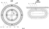
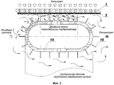
На фиг.1 изображен разрез описываемого аппарата; на фиг.2 - разрез Б-Б и В-В трубчатого мембранного модуля и тороидального турбулизатора соответственно; на фиг.3 - схема гидродинамического процесса во время движения тороидального турбулизатора вдоль поверхности полупроницаемой мембраны.Figure 1 shows a section of the described apparatus; figure 2 is a section bb and bb of the tubular membrane module and the toroidal turbulator, respectively; figure 3 is a diagram of a hydrodynamic process during the movement of a toroidal turbulizer along the surface of a semipermeable membrane.
Мембранный аппарат (фиг.1) содержит трубчатый мембранный модуль, выполненный в виде двух коаксиально расположенных цилиндров 1 и 2. Причем цилиндр 1 выполнен из пористого материала, на внутренней поверхности которого расположена полупроницаемая мембрана 3. Цилиндры 1 и 2 герметично соединены между собой при помощи фланцевых соединений 4, на боковых поверхностях которых установлены с одной стороны аппарата камера 5 для ввода исходного раствора через патрубок 6, а с другой стороны - камера 7 для вывода концентрата через патрубок 8. Цилиндр 2 снабжен патрубком 9 для удаления фильтрата.The membrane apparatus (figure 1) contains a tubular membrane module made in the form of two coaxially arranged
Внутри цилиндра 1 на поверхности полупроницаемой мембраны 3 неподвижно установлены стальные зубчатые рейки 10.Inside the
В трубчатом мембранном модуле (фиг.2) коаксиально поверхности полупроницаемой мембраны 3 расположен толкатель 11, на поверхности которого неподвижно закреплены опорные фасонные шайбы 13, равноудаленные друг от друга, к которым по окружности приварены стальные зубчатые рейки 12.In the tubular membrane module (FIG. 2), a
Оси симметрии зубчатых реек 10, расположенных на поверхности полупроницаемой мембраны 3, совпадают с осями симметрии зубчатых реек 12 толкателя 11.The axis of symmetry of the
Между зубчатыми рейками 10, расположенными на поверхности полупроницаемой мембраны 3, и зубчатыми рейками 12 толкателя 11 расположены тороидальные турбулизаторы 14, на внешней поверхности которых имеются замкнутые зубчатые ленты 15, выполненные из армированного прорезиненного материала и входящие в зацепление с рейками 10 и 12.Between the
Количество и расположение зубчатых реек 10, расположенных на поверхности полупроницаемой мембраны 3, и зубчатых реек 12 толкателя 11 выбирается таким образом, чтобы обеспечивалась правильная геометрическая форма тороидальных турбулизаторов 14.The number and location of the
Тороидальный турбулизатор 14 выполнен из материала, имеющего повышенный характер упругих деформаций. На внешней поверхности тороидального турбулизатора 14 имеются лопатки 16, выполненные из аналогичного материала и расположенные между замкнутыми зубчатыми лентами 15 таким образом, чтобы при движении тороидального турбулизатора 14 вдоль оси трубчатого мембранного модуля с поверхности полупроницаемой мембраны 3 удалялось максимальное количество слоя высокой концентрации.The
Количество тороидальных турбулизаторов 14 и шаг между ними выбираются таким образом, чтобы границы зон гидродинамического воздействия каждого тороидального турбулизатора соприкасались между собой при его движении в прямом и обратном направлениях.The number of
Камеры 5 и 7 для ввода исходного раствора и вывода концентрата соответственно выполнены таким образом, чтобы при движении тороидальных турбулизаторов 14 в прямом направлении одна торцевая часть толкателя 11 входила во внутреннее пространство камеры 5, а другая торцевая часть толкателя 11 выходила из внутреннего пространства камеры 7 и, наоборот, при движении тороидальных турбулизаторов в обратном направлении.The chambers 5 and 7 for the input of the initial solution and the output of the concentrate, respectively, are made in such a way that when the
Глубина входа и выхода торцевых частей толкателя 11 во внутренние пространства камер 5 и 7 определяется предельными положениями тороидальных турбулизаторов, прилегающих к соответствующим камерам при их движении в прямом и обратном направлениях.The depth of entry and exit of the end parts of the
Концевая часть толкателя 11, выходящая через герметизирующую обойму 17, закрепленную в камере 5 для ввода исходного раствора при помощи стопорного кольца 18, присоединена к механизму (не показан), обеспечивающему возвратно-поступательное движение толкателя 11 и, следовательно, тороидальных турбулизаторов 14 в прямом и обратном направлениях. Причем крайнее правое положение ведущего звена механизма, например кривошипно-шатунного (не показан), совпадает с предельным положением тороидального турбулизатора 14, прилегающему к камере 5 ввода исходного раствора при движении в обратном направлении, при котором одна торцевая часть толкателя 11 входит во внутреннее пространство камеры 7 вывода концентрата, а крайнее левое положение ведущего звена кривошипно-шатунного механизма - с предельным положением турбулизатора, прилегающего к камере 7 вывода концентрата при движении в прямом направлении, при котором другая торцевая часть толкателя 11 входит во внутреннее пространство камеры 5 ввода исходного раствора.The end part of the
Мембранный аппарат работает следующим образом.Membrane apparatus operates as follows.
Исходный раствор подается через патрубок 6 в камеру 5 под давлением, превышающим осмотическое.The initial solution is fed through the pipe 6 into the chamber 5 under a pressure exceeding the osmotic pressure.
Одновременно с этим с помощью кривошипно-шатунного механизма одна торцевая часть толкателя 11 входит во внутреннее пространство камеры 5 ввода исходного раствора, а тороидальные турбулизаторы 14 будут двигаться в прямом направлении до тех пор, пока ведущее звено кривошипно-шатунного механизма не займет крайнее левое положение, совпадающее с предельным положением тороидального турбулизатора 14, прилегающего к камере 7 вывода концентрата. После этого отключают электропитание привода кривошипно-шатунного механизма.At the same time, with the help of the crank mechanism, one end part of the
Прошедший через полупроницаемую мембрану 3 фильтрат скапливается в полости, образованной цилиндрами 1 и 2, откуда удаляется при помощи патрубка 9.Passed through a
После того как проницаемость полупроницаемой мембраны 3 уменьшится, включают электропитание привода кривошипно-шатунного механизма и толкатель 11, перемещаясь, приводит тороидальные турбулизаторы 14 в движение в обратном направлении.After the permeability of the
Поток исходного раствора (фиг.3), испытывая нарастающее сопротивление со стороны движущихся ему навстречу лопаток 16 тороидального турбулизатора 14, не может полностью проникнуть в кольцевой зазор, образованный полупроницаемой мембраной 3 и лопатками тороидального турбулизатора. В результате этого в этом кольцевом зазоре возникают противоточные микропотоки исходного раствора, усиливаемые перемещающимися лопатками тороидального турбулизатора и приводящие к дополнительному усилению гидродинамической неустойчивости в трубчатом мембранном модуле и, как следствие, удалению слоя высокой концентрации с поверхности полупроницаемой мембраны 3.The flow of the initial solution (Fig. 3), experiencing increasing resistance from the side of the
Удаляемые частицы слоя высокой концентрации отбрасываются лопатками 16 тороидального турбулизатора 14 в центральную область трубчатого мембранного модуля, откуда потоком исходного раствора, испытывающим в ней меньшее гидравлическое сопротивление, уносятся в камеру 7, из которой вместе с концентратом удаляются через патрубок 8.The removed particles of the high concentration layer are discarded by the
Тороидальные турбулизаторы 14, двигаясь в обратном направлении, удаляют слой высокой концентрации со всей поверхности полупроницаемой мембраны 3 и тем самым восстанавливают ее проницаемость.
Одновременно с этим другая торцевая часть толкателя 11 входит во внутреннее пространство камеры 7 вывода концентрата, а тороидальные турбулизаторы 14 будут двигаться в обратном направлении до тех пор, пока ведущее звено кривошипно-шатунного механизма не займет крайнее правое положение, совпадающее с предельным положением тороидального турбулизатора 14, прилегающего к камере 5 ввода исходного раствора.At the same time, the other end part of the
После этого отключают электропитание привода кривошипно-шатунного механизма и далее процессы повторяются аналогично описанным выше.After that, the power supply to the crank mechanism is turned off and then the processes are repeated as described above.
Данный мембранный аппарат позволяет обеспечить:This membrane apparatus allows you to provide:
- низкий уровень концентрационной поляризации и, как следствие, высокую эффективность процесса мембранной обработки за счет тороидальных турбулизаторов с лопатками на их внешней поверхности, движущихся попеременно в прямом и обратном направлениях вдоль поверхности полупроницаемой мембраны;- low concentration polarization and, as a result, high efficiency of the membrane treatment process due to toroidal turbulators with blades on their outer surface, moving alternately in the forward and reverse directions along the surface of the semipermeable membrane;
- широкий диапазон производительности за счет изменения числа оборотов ведущего звена кривошипно-шатунного механизма, количества тороидальных турбулизаторов и шага их размещения в мембранном канале;- a wide range of performance due to changes in the number of revolutions of the leading link of the crank mechanism, the number of toroidal turbulators and the step of their placement in the membrane channel;
- устранение зон со слабой гидродинамической активностью на участках полупроницаемой мембраны, прилегающих к фланцевым соединениям, благодаря периодическому приближению к ним тороидальных турбулизаторов.- elimination of zones with weak hydrodynamic activity in areas of a semipermeable membrane adjacent to flange joints due to the periodic approximation of toroidal turbulators to them.
Claims (1)
Priority Applications (1)
| Application Number | Priority Date | Filing Date | Title |
|---|---|---|---|
| RU2004120588/15A RU2269373C1 (en) | 2004-07-05 | 2004-07-05 | Membrane apparatus with the toroidal vortex generators |
Applications Claiming Priority (1)
| Application Number | Priority Date | Filing Date | Title |
|---|---|---|---|
| RU2004120588/15A RU2269373C1 (en) | 2004-07-05 | 2004-07-05 | Membrane apparatus with the toroidal vortex generators |
Publications (2)
| Publication Number | Publication Date |
|---|---|
| RU2004120588A RU2004120588A (en) | 2005-12-20 |
| RU2269373C1 true RU2269373C1 (en) | 2006-02-10 |
Family
ID=35869538
Family Applications (1)
| Application Number | Title | Priority Date | Filing Date |
|---|---|---|---|
| RU2004120588/15A RU2269373C1 (en) | 2004-07-05 | 2004-07-05 | Membrane apparatus with the toroidal vortex generators |
Country Status (1)
| Country | Link |
|---|---|
| RU (1) | RU2269373C1 (en) |
Cited By (1)
| Publication number | Priority date | Publication date | Assignee | Title |
|---|---|---|---|---|
| RU2680061C1 (en) * | 2018-03-29 | 2019-02-14 | Федеральное государственное бюджетное образовательное учреждение высшего образования "Воронежский государственный университет инженерных технологий" (ФГБОУ ВО "ВГУИТ") | Membrane apparatus with inflatable sleeves |
Citations (3)
| Publication number | Priority date | Publication date | Assignee | Title |
|---|---|---|---|---|
| SU1745320A1 (en) * | 1990-05-23 | 1992-07-07 | Ленинградский инженерно-строительный институт | Tubular membrane member |
| RU2174432C1 (en) * | 2000-12-04 | 2001-10-10 | Воронежская государственная технологическая академия | Membrane apparatus with nonstationary hydrodynamics |
| WO2003090911A1 (en) * | 2002-04-08 | 2003-11-06 | Nanyang Technological University | Ceramic membrane module |
-
2004
- 2004-07-05 RU RU2004120588/15A patent/RU2269373C1/en not_active IP Right Cessation
Patent Citations (3)
| Publication number | Priority date | Publication date | Assignee | Title |
|---|---|---|---|---|
| SU1745320A1 (en) * | 1990-05-23 | 1992-07-07 | Ленинградский инженерно-строительный институт | Tubular membrane member |
| RU2174432C1 (en) * | 2000-12-04 | 2001-10-10 | Воронежская государственная технологическая академия | Membrane apparatus with nonstationary hydrodynamics |
| WO2003090911A1 (en) * | 2002-04-08 | 2003-11-06 | Nanyang Technological University | Ceramic membrane module |
Cited By (1)
| Publication number | Priority date | Publication date | Assignee | Title |
|---|---|---|---|---|
| RU2680061C1 (en) * | 2018-03-29 | 2019-02-14 | Федеральное государственное бюджетное образовательное учреждение высшего образования "Воронежский государственный университет инженерных технологий" (ФГБОУ ВО "ВГУИТ") | Membrane apparatus with inflatable sleeves |
Also Published As
| Publication number | Publication date |
|---|---|
| RU2004120588A (en) | 2005-12-20 |
Similar Documents
| Publication | Publication Date | Title |
|---|---|---|
| CA2826439C (en) | Apparatus and method for removing finely divided solids from a liquid flow | |
| RU2016137161A (en) | ULTRA FILTRATION UNIT FOR CONTINUOUS REPLACEMENT OF A BUFFER SOLUTION OR MEDIUM FROM A PROTEIN SOLUTION | |
| AU2014276442B2 (en) | Method of operating a pressure-retarded osmosis plant | |
| KR20150144335A (en) | Osmosis apparatus | |
| RU2269373C1 (en) | Membrane apparatus with the toroidal vortex generators | |
| JP6033118B2 (en) | Reverse osmosis membrane device | |
| US3491021A (en) | Method and apparatus for non-cyclic concentration of solution-suspension | |
| IE37164B1 (en) | Apparatus for separating liquids into two fractions by means of semipermeable membranes | |
| RU2174432C1 (en) | Membrane apparatus with nonstationary hydrodynamics | |
| RU2016103631A (en) | DEVICE FOR CONCENTRATION OF PROCESSED OBJECT | |
| RU2429053C2 (en) | Membrane concentration apparatus | |
| WO2012125505A1 (en) | Interconnector for filtration apparatus with reduced permeate pressure loss | |
| JP2013081922A (en) | Seawater desalination apparatus | |
| RU2139130C1 (en) | Diaphragm concentration apparatus | |
| CN101524624A (en) | Gas drive membrane separation method and membrane separation device | |
| CN211111196U (en) | Filter core and purifier | |
| CN220003556U (en) | Glacier water treatment device | |
| RU2506990C1 (en) | Membrane apparatus with transient hydrodynamics | |
| RU2846390C1 (en) | Membrane apparatus | |
| RU2558894C1 (en) | Vertical membrane apparatus | |
| RU2560417C1 (en) | Membrane apparatus | |
| RU2813339C1 (en) | Membrane apparatus with nozzle turbulizer | |
| CN110697844A (en) | Filter core and purifier | |
| US4200531A (en) | Tubular membrane separation apparatus | |
| RU2680459C1 (en) | Membrane device with double action turbulator |
Legal Events
| Date | Code | Title | Description |
|---|---|---|---|
| MM4A | The patent is invalid due to non-payment of fees |
Effective date: 20060706 |