RU2267373C2 - Method for forming, mainly shapes with w-like cross section - Google Patents
Method for forming, mainly shapes with w-like cross section Download PDFInfo
- Publication number
- RU2267373C2 RU2267373C2 RU2004106507/02A RU2004106507A RU2267373C2 RU 2267373 C2 RU2267373 C2 RU 2267373C2 RU 2004106507/02 A RU2004106507/02 A RU 2004106507/02A RU 2004106507 A RU2004106507 A RU 2004106507A RU 2267373 C2 RU2267373 C2 RU 2267373C2
- Authority
- RU
- Russia
- Prior art keywords
- bending
- workpiece
- strip
- blank
- elements
- Prior art date
Links
Images

Landscapes
- Bending Of Plates, Rods, And Pipes (AREA)
- Forging (AREA)
Abstract
Description
Изобретение относится к обработке металлов давлением и может быть использовано в различных отраслях промышленности для изготовления из листа профилей.The invention relates to the processing of metals by pressure and can be used in various industries for the manufacture of sheet profiles.
Известен способ изготовления изделий из листовых заготовок, при котором производят предварительную гибку полосы, образуя радиусный участок между элементами заготовки, а затем осуществляют ее окончательную гибку путем приложения нормальных и тангенциальных усилий к элементам заготовки [1].A known method of manufacturing products from sheet blanks, in which they pre-bend the strip, forming a radius section between the elements of the workpiece, and then carry out its final bending by applying normal and tangential forces to the elements of the workpiece [1].
Недостатком известного технического решения является то, что необходимо производить экспериментальную отладку технологического процесса гибки для обеспечения заданной точности.A disadvantage of the known technical solution is that it is necessary to carry out experimental debugging of the bending process to ensure a given accuracy.
Наиболее близким к предлагаемому изобретению по технической сущности и достигаемому эффекту является способ изготовления профилей преимущественно W-образного сечения, при котором производят предварительную гибку полосы, образуя радиусные участки между элементами заготовки, а окончательную гибку центральной части заготовки до требуемого размера путем приложения нормальных и тангенсальных усилий к элементам заготовки [2].The closest to the proposed invention in terms of technical nature and the achieved effect is a method for manufacturing predominantly W-shaped sections, in which the strip is pre-bent to form radius sections between the workpiece elements, and the central part of the workpiece is finally bent to the required size by applying normal and tangential forces to the elements of the workpiece [2].
Известное решение позволяет уменьшить радиус изгиба профилей, снизить пружинение изгибаемого материала, однако утонение, возникающее в радиусных участках, не обеспечивает требуемого качества изготовления деталей.The known solution allows to reduce the bending radius of the profiles, to reduce the springing of the bending material, however, the thinning that occurs in the radius sections does not provide the required quality of manufacturing parts.
Технический результат, достигаемый при использовании предлагаемого изобретения, заключается в повышении качества изготовления деталей W-образной формы за счет исключения утонения материала в радиусных участках детали.The technical result achieved by using the present invention is to improve the manufacturing quality of W-shaped parts by eliminating the thinning of the material in the radius sections of the part.
Достижение указанного технического результата от использования разработанного изобретения обеспечивается тем, что в способе изготовления профилей преимущественно W-образного сечения, при котором производят предварительный изгиб полосы, образуя радиусные участки между элементами заготовки, а затем ее окончательный изгиб путем приложения нормальных и тангенциальных усилий к элементам заготовки, предложено предварительный изгиб сопровождать изгибом центральной части полосы с одновременным приданием элементам центральной части цилиндрической вогнутой формы, максимальный прогиб которых находится в пределах от 0,5 до 0,6 исходной толщины полосы, а окончательный изгиб осуществляется после приложения нормальных усилий на периферийные части заготовки с последующим распрямлением центральных вогнутых элементов заготовки.The achievement of the specified technical result from the use of the developed invention is ensured by the fact that in the method for manufacturing profiles of predominantly W-shaped section, in which the strip is pre-bent to form radius sections between the workpiece elements, and then its final bend by applying normal and tangential forces to the workpiece elements It is proposed to accompany the preliminary bending with the bending of the central part of the strip while simultaneously giving the elements of the central part of the cylinder ndricheskoy concave shape, that the maximum deflection which is between 0.5 to 0.6 of the original thickness of the strip, and the final bend is made after application of normal forces to the peripheral portion of the preform, followed by straightening the concave central elements of the workpiece.
Сущность разработанного технического решения поясняется чертежом, на котором представлены этапы изготовления гибкой профиля W-образного сечения из листовой заготовки:The essence of the developed technical solution is illustrated by the drawing, which shows the stages of manufacturing a flexible profile of a W-shaped section from a sheet stock:
- на фиг.1 показано исходное положение заготовки перед предварительной гибкой центральной части заготовки;- figure 1 shows the initial position of the workpiece before the preliminary flexible central part of the workpiece;
- на фиг.2 показано положение заготовки после предварительной гибки центральной части заготовки;- figure 2 shows the position of the workpiece after preliminary bending the Central part of the workpiece;
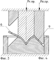
- на фиг.3 показано положение заготовки перед предварительной гибкой периферийных участков заготовки;- figure 3 shows the position of the workpiece before the preliminary flexible peripheral sections of the workpiece;
- на фиг.4 показано положение заготовки после предварительной гибки периферийных участков заготовки;- figure 4 shows the position of the workpiece after preliminary bending of the peripheral sections of the workpiece;
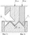
- на фиг.5 показано положение заготовки перед началом окончательной гибки с распрямлением центральных участков заготовки;- figure 5 shows the position of the workpiece before starting the final bending with straightening of the central sections of the workpiece;
- на фиг.6 показано положение заготовки после окончательной гибки с распрямлением центральных участков заготовки;- figure 6 shows the position of the workpiece after final bending with straightening of the central sections of the workpiece;
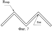
- на фиг.7 показана W-образная заготовка после окончания гибки;- Fig.7 shows a W-shaped workpiece after bending;
- на фиг.8 показана W-образная деталь после окончательной гибки.- Fig. 8 shows a W-shaped part after final bending.
Предложенный способ осуществляется в устройствах, которые состоят из следующих основных деталей.The proposed method is carried out in devices that consist of the following main parts.
К внутреннему ползуну пресса (не показан) прикреплен центральный пуансон 1, а к наружному ползуну пресса прикреплены периферийные пуансоны 2. На столе пресса установлена гибочная матрица 3 с прикрепленными к ней боковинами 4. На боковинах 4 закреплены установочные рамки 5, при помощи которых плоская заготовка 6 ориентирована в направлении как вдоль, так и поперек осевой линии штампа в плане.A central punch 1 is attached to the inner slider of the press (not shown), and peripheral punches 2 are attached to the external slider of the press 2. On the press table there is a bending matrix 3 with sidewalls attached to it 4. On the sidewalls 4, mounting frames 5 are fixed, with which a flat blank 6 is oriented in the plan both along and across the center line of the stamp.
Заготовке 6 на этапах гибки согласно фиг.2-6 присвоены позиции 7-11. Гибка плоской листовой заготовки 6 в деталь W-образного сечения осуществляется следующим образом.The
После размещения плоской листовой заготовки 6 в установочной рамке 5 в штампе для предварительной гибки включается рабочий ход внутреннего ползуна пресса вниз, перемещение которого вместе с центральным пуансоном 1 приводит к предварительному изгибу центральной части заготовки 6 в положение согласно фиг.2 в процессе смыкания пуансона 1 с центральной частью матрицы 3. В связи с тем что пуансон 1 имеет вогнутую форму рабочей части, а центральная часть матрицы 3 имеет выпуклую форму, заготовка 7 приобретает вогнутую форму. После чего поступает команда на перемещение вниз наружного ползуна пресса вместе с периферийными пуансонами 2, которые обеспечивают изгиб периферийной части заготовки 9 (см. фиг.4). После предварительной гибки заготовку 9 устанавливают в штамп для окончательной штамповки (см. фиг.5). Окончательную гибку центральных вогнутых участков заготовки 10 (см. фиг.5) осуществляют после предварительного прижатия периферийных участков заготовки 10 периферийными пуансонами 2, перемещением центрального пуансона 1 до смыкания с заготовкой 11 и матрицей 3. В результате того что рабочие поверхности пуансона 1 и центральной части матрицы 3 в штампе для окончательной штамповки являются плоскими, центральные стенки заготовки 11 и три радиусных участка подвергаются сжатию, при распрямлении центрального участка заготовки 11 происходит перераспределение материала центральной части заготовки, приводящее к уменьшению наружных радиусов радиусных участков до значений, близких к нулевым. После окончания изгиба детали 11 центральный и периферийный пуансоны 1 и 2 возвращаются в крайнее верхнее положение, отштампованная деталь 11 удаляется из рабочей зоны устройства.After placing the flat sheet blank 6 in the mounting frame 5 in the stamp for pre-bending, the working stroke of the internal press slider down is turned on, moving it together with the central punch 1 leads to preliminary bending of the central part of the blank 6 to the position according to FIG. 2 during the closing of the punch 1 s the central part of the matrix 3. Due to the fact that the punch 1 has a concave shape of the working part, and the central part of the matrix 3 has a convex shape, the workpiece 7 acquires a concave shape. After that, a command is received to move down the outer slider of the press together with the peripheral punches 2, which provide bending of the peripheral part of the workpiece 9 (see figure 4). After preliminary bending, the
Очевидно, что предварительная штамповка центральной части заготовки 9 должна быть такой, чтобы при окончательной гибке с сжатием стенок и изделия и его радиусных участков согласно фиг.6 обеспечивалось спрямление центральной части без потери устойчивости ее.Obviously, the preliminary stamping of the central part of the
В этом случае максимальный прогиб вогнутых цилиндрических участков центральной зоны заготовки 5 должен находиться в пределах 0,5-0,6 от толщины заготовки 6, чем обеспечивается уменьшение радиусов радиусных участков и предотвращение потери устойчивости центральной части заготовки.In this case, the maximum deflection of the concave cylindrical sections of the Central zone of the workpiece 5 should be in the range of 0.5-0.6 from the thickness of the
Пример осуществления предложенного способа гибки. Для изготовления профилей W-образного сечения из жаропрочной стали с пределом прочности σв=80 кг/мм2 и с пределом текучести σS=50 кг/мм2, при следующих параметрах изделия: толщина S=1,0 мм, радиус гиба r=0,2 мм, при высоте Н=50 мм и ширине 50 мм четырех прямоугольных стенок детали, расчет заготовки осуществляется согласно справочникам по холодной штамповке (например [3], с.137). Максимальный прогиб центральной части заготовки, при предварительной штамповке, принимаем равным 0,5×S=0.5×1.0=0.5 мм.An example implementation of the proposed method are flexible. For the manufacture of W-shaped sections from heat-resistant steel with a tensile strength σ in = 80 kg / mm 2 and a yield strength σ S = 50 kg / mm 2 , with the following product parameters: thickness S = 1.0 mm, bending radius r = 0.2 mm, with a height H = 50 mm and a width of 50 mm of four rectangular walls of the part, the calculation of the workpiece is carried out according to the cold stamping guides (for example [3], p.137). The maximum deflection of the central part of the workpiece, with preliminary stamping, is taken to be 0.5 × S = 0.5 × 1.0 = 0.5 mm.
Усилие предварительной гибки на центральном пуансоне Pг. пр. определяется из условия создания напряжений в радиусной части заготовки и в стенках изделия не более предела текучести, т.е.Prebending the central force of the punch P ave. Determined from the radius create stresses in the portion of the preform and the walls of the product is not more than the yield stress, i.e.
![]()
![]()
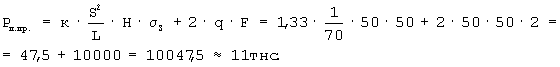
Усилие гибки Рп с правкой периферийных стенок (согласно /3/, с.145) в процессе предварительной гибке рассчитывается по формуле:The bending force R p with editing the peripheral walls (according to / 3 /, p.145) in the process of preliminary bending is calculated by the formula:
После предварительной гибки деталь имеет W-образную форму с вогнутыми цилиндрическими стенками центрального участка заготовки. Максимальный прогиб стенок центрального участка равен 0,5 мм.After preliminary bending, the part has a W-shape with concave cylindrical walls of the central section of the workpiece. The maximum deflection of the walls of the central section is 0.5 mm.
Окончательную гибку заготовки 10 (см. фиг.5) осуществляют после установки заготовки в штамп для окончательной гибки. Производят прижатия периферийных участков заготовки 10 периферийными пуансонами 2 с усилием Ро.п., которое принимается равным усилию предварительной гибки периферийных участков и которое равно 11 тнс.The final bending of the workpiece 10 (see figure 5) is carried out after installing the workpiece in the stamp for final bending. The peripheral sections of the workpiece are pressed by 10 peripheral punches 2 with a force of R o.p. , which is taken equal to the effort of preliminary bending of peripheral sections and which is equal to 11 tns.
Перемещение центрального пуансона 1 до смыкания с заготовкой 11 и матрицей 3 приводит к выпрямлению вогнутых цилиндрических участков, максимальный прогиб которых равен 0,5 мм. Усилие на центральном пуансоне Ро.ц. определяется:The movement of the Central punch 1 to close with the workpiece 11 and the matrix 3 leads to the straightening of the concave cylindrical sections, the maximum deflection of which is 0.5 mm. Effort on the central punch R o.ts. determined by:
![]()
![]()
Таким образом для изготовления профилей W-образного сечения разработаны приемы и установлены силовые параметры осуществления представленного технического решения.Thus, for the manufacture of profiles of a W-shaped section, techniques have been developed and the power parameters of the implementation of the presented technical solution have been established.
Источники информацииInformation sources
1. Авторское свидетельство №657888 (СССР) М. Кл. B 21 D 5/00 "Способ изготовления профилей". БИ №15, 1979.1. Copyright certificate No. 657888 (USSR) M. Kl. B 21 D 5/00 "Method for the production of profiles". BI No. 15, 1979.
2. Патент RU №2110348 В 21 D 5/00, 22/02 "Способ изготовления профилей преимущественно W-образного сечения", Бюл. №13, 1998 г.2. Patent RU No. 2110348 B 21 D 5/00, 22/02 "Method for the manufacture of predominantly W-shaped sections," Bull. No. 13, 1998
3. Малов А.Н. Технология холодной штамповки. М.: Машиностроение, 1969, с.145.3. Malov A.N. Cold stamping technology. M.: Mechanical Engineering, 1969, p. 145.
Claims (1)
Priority Applications (1)
| Application Number | Priority Date | Filing Date | Title |
|---|---|---|---|
| RU2004106507/02A RU2267373C2 (en) | 2004-03-05 | 2004-03-05 | Method for forming, mainly shapes with w-like cross section |
Applications Claiming Priority (1)
| Application Number | Priority Date | Filing Date | Title |
|---|---|---|---|
| RU2004106507/02A RU2267373C2 (en) | 2004-03-05 | 2004-03-05 | Method for forming, mainly shapes with w-like cross section |
Publications (2)
| Publication Number | Publication Date |
|---|---|
| RU2004106507A RU2004106507A (en) | 2005-08-27 |
| RU2267373C2 true RU2267373C2 (en) | 2006-01-10 |
Family
ID=35846547
Family Applications (1)
| Application Number | Title | Priority Date | Filing Date |
|---|---|---|---|
| RU2004106507/02A RU2267373C2 (en) | 2004-03-05 | 2004-03-05 | Method for forming, mainly shapes with w-like cross section |
Country Status (1)
| Country | Link |
|---|---|
| RU (1) | RU2267373C2 (en) |
Cited By (1)
| Publication number | Priority date | Publication date | Assignee | Title |
|---|---|---|---|---|
| RU2791199C1 (en) * | 2022-02-11 | 2023-03-03 | Общество с ограниченной ответственностью "Технощит" | Method for manufacturing w-shaped profiles from sheet metal billets |
Citations (1)
| Publication number | Priority date | Publication date | Assignee | Title |
|---|---|---|---|---|
| RU2110348C1 (en) * | 1996-11-29 | 1998-05-10 | Товарищество с ограниченной ответственностью "Технощит" | Method of making sections mainly w-shaped ones |
-
2004
- 2004-03-05 RU RU2004106507/02A patent/RU2267373C2/en not_active IP Right Cessation
Patent Citations (1)
| Publication number | Priority date | Publication date | Assignee | Title |
|---|---|---|---|---|
| RU2110348C1 (en) * | 1996-11-29 | 1998-05-10 | Товарищество с ограниченной ответственностью "Технощит" | Method of making sections mainly w-shaped ones |
Cited By (1)
| Publication number | Priority date | Publication date | Assignee | Title |
|---|---|---|---|---|
| RU2791199C1 (en) * | 2022-02-11 | 2023-03-03 | Общество с ограниченной ответственностью "Технощит" | Method for manufacturing w-shaped profiles from sheet metal billets |
Also Published As
| Publication number | Publication date |
|---|---|
| RU2004106507A (en) | 2005-08-27 |
Similar Documents
| Publication | Publication Date | Title |
|---|---|---|
| CN105792957B (en) | Compression molding device, used the shaped device compressing product manufacture method and compressing product | |
| CN106825153B (en) | A kind of accurate continuous bending method of U-shaped heavy forging | |
| RU2692353C1 (en) | Production method of pressed products and production line for them | |
| CN111727089B (en) | Method for manufacturing press-molded member, press-molding device, and metal plate for press-molding | |
| WO2011024246A1 (en) | Press forming method | |
| CN110709181B (en) | Manufacturing method of press-molded product and press production line | |
| CN110935759B (en) | U-O shaping of members bent about three spatial axes | |
| KR101867744B1 (en) | Press forming method and method for manufacturing pressed product as well as press forming apparatus | |
| CN107635684A (en) | Impact forming method and punch-forming mold | |
| CN106488816A (en) | Manufacturing method of forged crankshaft | |
| CN212384384U (en) | Bending, rounding and stamping progressive die for parts with multi-layer drum-shaped structures | |
| CN103624117B (en) | The method and apparatus of abrupt bend high strength panel | |
| JP2001314918A (en) | Press forming method and apparatus | |
| RU2267373C2 (en) | Method for forming, mainly shapes with w-like cross section | |
| CN119114831B (en) | Forming method and forming system for seamless frame forging | |
| JP7226382B2 (en) | Method for manufacturing pressed parts, die for unbending, and method for forming pressed parts | |
| CN117295565A (en) | Stamping forming method | |
| CN111182979A (en) | Method and device for producing a profiled sheet metal component by means of a preform component | |
| JP4232451B2 (en) | Press working method with excellent shape freezing | |
| RU2791199C1 (en) | Method for manufacturing w-shaped profiles from sheet metal billets | |
| RU2194587C2 (en) | Method for shaping double-curvature parts | |
| RU2110348C1 (en) | Method of making sections mainly w-shaped ones | |
| JP3997907B2 (en) | Pressing method with excellent shape freezing | |
| RU2527820C2 (en) | Method of forging box from steel blank at simple-action press | |
| JP7854972B2 (en) | Press forming method |
Legal Events
| Date | Code | Title | Description |
|---|---|---|---|
| MM4A | The patent is invalid due to non-payment of fees |
Effective date: 20090306 |