RU2267199C1 - Arrangement for fastening a cable - Google Patents
Arrangement for fastening a cable Download PDFInfo
- Publication number
- RU2267199C1 RU2267199C1 RU2004109412/09A RU2004109412A RU2267199C1 RU 2267199 C1 RU2267199 C1 RU 2267199C1 RU 2004109412/09 A RU2004109412/09 A RU 2004109412/09A RU 2004109412 A RU2004109412 A RU 2004109412A RU 2267199 C1 RU2267199 C1 RU 2267199C1
- Authority
- RU
- Russia
- Prior art keywords
- base
- cable
- fastening
- arrangement
- cables
- Prior art date
Links
Images

Landscapes
- Installation Of Indoor Wiring (AREA)
- Suspension Of Electric Lines Or Cables (AREA)
- Clamps And Clips (AREA)
Abstract
Description
Изобретение относится к электротехнике и может найти применение при прокладке кабеля.The invention relates to electrical engineering and may find application in cable laying.
Известен держатель для крепления кабелей и шин по авт. свид. № 970530 (опубл. 30.10.82), содержащий основание, подвижно закрепленные вдоль его продольной оси изоляционные элементы в виде цилиндрических роликов, каждый из которых выполнен с проточкой на боковой поверхности и торцевым выступом с параллельными лысками, взаимодействующими с пазом основания, и фиксирующие болты, установленные в изоляционных элементах, причем каждый изоляционный элемент со стороны, противоположной основанию, выполнен с двумя диаметрально расположенными дополнительными выступами, перпендикулярными его торцу, в которых выполнены осевые пазы, лыски первых выступов ориентированы перпендикулярно оси пазов, при этом в пазах каждых двух дополнительных выступов смежных деталей установлен фиксирующий болт.Known holder for mounting cables and tires by ed. testimonial. No. 970530 (publ. 30.10.82) containing a base, insulating elements in the form of cylindrical rollers, movably fixed along its longitudinal axis, each of which is made with a groove on the side surface and an end protrusion with parallel flats interacting with the base groove, and fixing bolts installed in the insulating elements, each insulating element on the side opposite to the base is made with two diametrically arranged additional protrusions perpendicular to its end, in which Nena axial slots, flats first projections are oriented perpendicular to the axis of the grooves, the grooves in each of the two additional lugs of adjacent parts mounted locking bolt.
Держатель предназначен для определенного типоразмера кабеля, что создает неудобства при работе с кабелем различного типоразмера, данная конструкция сложна в изготовлении и эксплуатации, нетехнологична.The holder is designed for a specific cable size, which creates inconvenience when working with a cable of various sizes, this design is difficult to manufacture and operate, low-tech.
От указанного недостатка свободен лоток для кабеля по свидетельству на полезную модель № 29412 (опубл. 10.05.03), содержащее основание, подвижно закрепленные вдоль его продольной оси изоляционные элементы, взаимодействующие с пазом основания и фиксирующие болты, установленные в изоляционных элементах, причем каждый изоляционный элемент выполнен в форме параллелепипеда, в двух противоположных плоскостях в средней его части выполнены проточки трапецеидальной формы верхним основанием к центру параллелепипеда, изоляционный элемент может быть выполнен с использованием материалов различной цветовой гаммы, а также с флюорисцентным покрытием.According to the utility model certificate No. 29412 (publ. 10.05.03), the cable tray is free from this drawback, containing a base, insulating elements movably fixed along its longitudinal axis, interacting with the base groove and fixing bolts installed in the insulating elements, each insulating the element is made in the form of a parallelepiped, in two opposite planes in its middle part grooves of a trapezoidal shape are made with the upper base to the center of the parallelepiped, the insulating element can be made using materials of various colors, as well as with a fluorescent coating.
Лоток данной конструкции очень металлоемок, имеет большой вес.The tray of this design is very metal-intensive, has a lot of weight.
Известен лоток для укладки кабеля по свидетельству на полезную модель № 28659 (опубл. 27.03.2003), содержащий ребра, установленные перпендикулярно одно другому с образованием решетки и узлы крепления, причем ребра выполнены из прутков, а ребра основания выполнены П-образной формы, узлы крепления выполнены из скоб, зафиксированных попарно на месте пересечения ребер, причем скобы зафиксированы с разворотом одна относительно другой на 180°.Known tray for cable laying according to the certificate for utility model No. 28659 (publ. 03/27/2003), containing ribs installed perpendicular to one another with the formation of a lattice and attachment nodes, and the ribs are made of rods, and the ribs of the base are made in a U-shape, nodes the fasteners are made of brackets fixed in pairs at the intersection of the ribs, and the brackets are fixed with a turn of one relative to another 180 °.
При эксплуатации лотков данной конструкции выявлены следующие недостатки: неудобство при необходимости замены кабеля, т.к. кабель в процессе эксплуатации перепутывается.When operating the trays of this design, the following disadvantages were identified: inconvenience if cable replacement is necessary, because the cable gets mixed up during operation.
Известно приспособление по патенту US № 5435507 (опубл. 17 марта 1994 г.), легко монтируемое и имеющее широкие возможности для крепления кабеля различного типоразмера.The device according to US patent No. 5435507 (publ. March 17, 1994) is known, which is easily mounted and has ample opportunities for fastening a cable of various sizes.
Приспособление предназначено для одного кабеля, громоздко.The fixture is designed for one cable, bulky.
Предлагаемым изобретением решается задача создания устройства удобного в изготовлении, не требующего дополнительного проектирования и затрат при креплении на поверхность различного рельефа, предназначенного для крепления большого количества кабеля, удобного для укладки, эксплуатации и замены поврежденного кабеля или замены кабеля на другой типоразмер, удобной пространственной фиксации, упрощения технологии монтажа провода и сокращения времени при укладке и замене кабеля.The present invention solves the problem of creating a device that is convenient to manufacture, does not require additional design and costs when attaching to the surface of various reliefs, designed to attach a large number of cables, convenient for laying, operating and replacing a damaged cable or replacing a cable with another size, convenient spatial fixation, simplification of wire installation technology and reduction of time when laying and replacing the cable.
Для достижения указанного технического результата в устройстве для крепления кабелей или шин, содержащем основание, изоляционные элементы и фиксирующие болты, установленные в изоляционных элементах, изоляционные элементы крепятся к основанию, выполненному из набора парных, расположенных параллельно прутков при помощи крепежного элемента, которое прижимается к основанию, причем крепежный элемент, имеет профильные изгибы противоположных кромок, а основание изоляционного элемента и крепежный элемент выполнены квадратной формы.To achieve the specified technical result in a device for attaching cables or tires containing a base, insulating elements and fixing bolts installed in the insulating elements, the insulating elements are attached to the base, made of a set of paired, parallel rods with a fastening element, which is pressed against the base moreover, the fastening element has profile bends of opposite edges, and the base of the insulating element and the fastening element are square in shape.
Отличительными признаками предлагаемого устройства от указанного выше является то, что изоляционные элементы крепятся к основанию, выполненному из набора парных, расположенных параллельно прутков при помощи крепежного элемента, которое прижимается к основанию, причем крепежный элемент имеет профильные изгибы противоположных кромок, а основание изоляционного элемента и крепежный элемент выполнены квадратной формы.Distinctive features of the proposed device from the above is that the insulating elements are attached to the base, made of a set of paired parallel bars using a fastening element, which is pressed against the base, and the fastening element has profile bends of opposite edges, and the base of the insulating element and fixing The element is square.
Предлагаемая конструкция иллюстрируется чертежами, гдеThe proposed design is illustrated by drawings, where
на фиг.1 показано устройство для крепления кабеля в сборе;figure 1 shows a device for mounting the cable assembly;
на фиг.2 - крепление изоляционного элемента к скобе;figure 2 - fastening of the insulating element to the bracket;
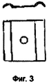
на фиг.3 - скоба.figure 3 - bracket.
Устройство состоит из основания 1 (фиг.1, 2), выполненного из набора, размещенных параллельно друг другу пар опорных прутков. Ширина устройства зависит от количества кабелей, которые на них предполагается крепить при помощи изоляционных элементов 2 (фиг.2), выполненных в форме параллелепипеда, причем в двух противоположных плоскостях в средней части изоляционного элемента выполнены проточки трапецеидальной формы верхним основанием к центру параллелепипеда, необходимые для крепления кабеля. Изоляционный элемент имеет сквозное отверстие под болт 4, расположенное в центре основания, которое имеет форму, идентичную форме скобы 3 (фиг.3). Скоба имеет профильные изгибы противоположных кромок. Профильные изгибы противоположных кромок выполняются глубиной не менее диаметра опорных прутков. Основание изоляционного элемента выполнено квадратной формы.The device consists of a base 1 (1, 2), made of a set of pairs of support rods placed parallel to each other. The width of the device depends on the number of cables that are supposed to be mounted on them using insulating elements 2 (Fig. 2) made in the form of a parallelepiped, and in two opposite planes in the middle part of the insulating element grooves of a trapezoidal shape are made with the upper base to the center of the parallelepiped, necessary for cable mounts. The insulating element has a through hole for the bolt 4, located in the center of the base, which has a shape identical to the shape of the bracket 3 (figure 3). The bracket has profile bends of opposite edges. Profile bends of opposite edges are performed with a depth of not less than the diameter of the support rods. The base of the insulating element is square in shape.
Устройство собирается непосредственно в помещении, где необходимо крепить кабель. Для этого пруток может быть доставлен в любом виде: предварительно заготовленный определенной длины или в бухтах и нарезаться определенных размеров на месте, затем прутки крепятся (фиг.1, 2) перпендикулярно или под любым углом к несущим конструкциям попарно параллельно с расстоянием до следующей «пары» достаточным для того, чтобы кабель не провис под действием силы тяжести. Крепление прутков к несущим конструкциям может быть выполнено любым известным способом, под любым углом к опоре, а также устройства для крепления кабеля могут соединяться между собой в любых комбинациях. Также прутки могут навешиваться (фиг.2) на несущие конструкции, либо могут быть образованы напольные конструкции. Затем к основаниям, выполненным из прутков, крепятся изоляционные элементы 2, с одной стороны, которые «прижимаются» к основанию скобами 3, имеющими в центре сквозное отверстие и профильные изгибы противоположных кромок. Основание изоляционного элемента выполнено квадратной формы, причем сторона основания изоляционного элемента равна стороне крепежного элемента, который выполнен квадратной формы. Изоляционный элемент крепится к скобе, в профильных изгибах которой размещены опорные прутки при помощи болтового соединения. Кабель укладывается между изоляционными элементами в образовавшиеся между ними отверстия перпендикулярно к опорным пруткам и изоляционные элементы фиксируются болтовым соединением.The device is assembled directly in the room where you need to attach the cable. For this, the bar can be delivered in any form: pre-harvested of a certain length or in bays and cut into certain sizes in place, then the bars are attached (Fig. 1, 2) perpendicularly or at any angle to the supporting structures in pairs in parallel with the distance to the next "pair »Sufficient so that the cable does not sag due to gravity. The fastening of the rods to the supporting structures can be performed by any known method, at any angle to the support, and also the cable fastening devices can be interconnected in any combination. Also, the rods can be hung (figure 2) on the supporting structure, or floor structures can be formed. Then,
По количеству изоляционных элементов необходимо на один больше, чем количество кабелей, которые необходимо закрепить. Изоляционные элементы соединяются со скобой при помощи болтового соединения.The number of insulating elements requires one more than the number of cables that need to be fixed. The insulating elements are connected to the bracket using a bolted connection.
Устройство по сравнению с проволочными лотками, у которых ребра выполнены из прутков, причем ребра основания выполнены П-образной формы, не имеет продольных прутков, т.е. имеет место исключения элемента известного устройства с сохранением функции исключенного элемента, по сравнению с приспособлением по патенту US № 5435507 предлагаемое устройство предназначено для крепления большого количества кабеля, имеет простую конструкцию, неметаллоемко, т.е. известная задача решается с помощью нового устройства для крепления кабеля, упрощается технология монтажа и демонтажа устройства, а также сокращается время монтажа и демонтажа устройства.The device, in comparison with wire trays, in which the ribs are made of rods, and the ribs of the base are made in a U-shape, does not have longitudinal rods, i.e. there is an exception of the element of the known device while maintaining the function of the excluded element, compared with the device according to US patent No. 5435507, the proposed device is designed to attach a large number of cables, has a simple structure, non-metal-intensive, i.e. The well-known problem is solved with the help of a new device for cable fastening, the technology of installation and dismantling of the device is simplified, and the time of installation and dismantling of the device is also reduced.
Монтаж проволочных лотков исключает применение большого количества компонентов, которые необходимы при монтаже традиционных стальных лотков. Изменение направления и уровня лотков производится прямо на месте монтажа с помощью болтовых зажимов и скоб. Проволочная структура лотка обеспечивает легкую укладку и закрепление любых типов кабелей, а также позволяет быстро и с минимальными затратами изменять и дополнять кабельную разводку без демонтажа и крупных переделок. Открытая структура обеспечивает лучшее охлаждение высоконагруженных кабелей и их периодический осмотр в процессе эксплуатации.Installation of wire trays eliminates the use of a large number of components that are necessary for the installation of traditional steel trays. Changing the direction and level of the trays is made directly at the installation site using bolt clamps and brackets. The wire structure of the tray provides easy laying and fastening of any type of cable, and also allows you to quickly and at minimal cost to change and supplement the cable routing without dismantling and major alterations. The open structure provides better cooling of heavily loaded cables and their periodic inspection during operation.
В помещениях, где очень важно соблюдение гигиены, минимальная площадь поверхности устройства снижает скопление пыли и грязи.In rooms where hygiene is very important, the minimum surface area of the device reduces the accumulation of dust and dirt.
Структура устройства для крепления кабеля позволяет надежно фиксировать кабель. Крепление прутков к несущим конструкциям может быть выполнено любым известным способом, под любым углом к опоре, а также прутки могут соединяться между собой в любых комбинациях.The structure of the cable attachment device allows you to securely fix the cable. The fastening of the rods to the supporting structures can be performed by any known method, at any angle to the support, and the rods can be connected to each other in any combination.
Данное конструктивное выполнение устройства для крепления кабеля позволяет легко и быстро укладывать кабель, учитывая рельеф поверхности, укладывать кабель различного типоразмера, создавая любые формы кабельных сетей с ответвлениями, округлениями, пересечениями, изгибами с минимальным количеством компонентов.This design of the cable fastening device allows easy and quick cable laying, taking into account the surface topography, laying cable of various sizes, creating any form of cable networks with branches, rounding, intersections, bends with a minimum number of components.
Устройство для крепления кабеля может быть установлено на любой поверхности: стена, пол, потолок, горизонтально или вертикально, а также оно дает возможность размещать кабель в любой плоскости, плавно переходить из одной плоскости в другую, эффективно и технологично прокладывать кабельные линии вдоль любой поверхности, даже несмотря на сложный рельеф. Группы кабелей различных марок, типоисполнения и назначения (например, силовые кабели и электропроводка) могут прокладываться непосредственно друг под другом, на одном основании. Возможность путаницы различных кабелей (и соответственно групп кабелей) исключается. Кроме того, достаточно легко отследить направление прокладки любых кабельных линий и при необходимости быстро и удобно заменить, демонтировать или добавить нужный кабель, для этого изоляционные элементы могут выполняться разноцветными, а также с флюориесцентным покрытием.The device for attaching the cable can be installed on any surface: wall, floor, ceiling, horizontally or vertically, and it also makes it possible to place the cable in any plane, smoothly switch from one plane to another, efficiently and technologically lay cable lines along any surface, even despite the difficult terrain. Groups of cables of various brands, types and designs (for example, power cables and wiring) can be laid directly under each other, on the same base. The possibility of confusion between different cables (and, accordingly, cable groups) is excluded. In addition, it is easy enough to track the direction of laying of any cable lines and, if necessary, quickly and conveniently replace, dismantle or add the desired cable, for this, the insulating elements can be multi-colored, as well as with a fluorescent coating.
При этом способе прокладки соблюдаются также все правила пожаро- и технико-безопасности и ПУЭ. Кабельные линии вплотную друг к другу не примыкают, что уменьшает их нагрев, и, тем самым, можно говорить об энергосберегающей компоненте.With this method of laying, all fire and technical safety rules and PUE are also observed. Cable lines are not adjacent to each other, which reduces their heating, and, thus, we can talk about an energy-saving component.
С использованием данного устройства можно строить кабельные линии любой конфигурации на любом расстоянии от поверхности (фиг.1, 2). При использовании данного устройства повышается надежность и удобство крепления кабеля, обеспечивается надежное крепления кабеля различных марок, типоисполнения и назначения (например, силовые, компьютерные, цепи управления), снижается трудоемкость монтажных работ, сокращается время монтажа и демонтажа кабельных линий.Using this device, you can build cable lines of any configuration at any distance from the surface (Fig.1, 2). When using this device, the reliability and convenience of cable fastening is increased, reliable cable fastening of various brands, type design and purpose (for example, power, computer, control circuits) is ensured, the complexity of installation works is reduced, the time of installation and dismantling of cable lines is reduced.
Claims (1)
Priority Applications (1)
| Application Number | Priority Date | Filing Date | Title |
|---|---|---|---|
| RU2004109412/09A RU2267199C1 (en) | 2004-03-29 | 2004-03-29 | Arrangement for fastening a cable |
Applications Claiming Priority (1)
| Application Number | Priority Date | Filing Date | Title |
|---|---|---|---|
| RU2004109412/09A RU2267199C1 (en) | 2004-03-29 | 2004-03-29 | Arrangement for fastening a cable |
Publications (2)
| Publication Number | Publication Date |
|---|---|
| RU2004109412A RU2004109412A (en) | 2005-10-20 |
| RU2267199C1 true RU2267199C1 (en) | 2005-12-27 |
Family
ID=35862421
Family Applications (1)
| Application Number | Title | Priority Date | Filing Date |
|---|---|---|---|
| RU2004109412/09A RU2267199C1 (en) | 2004-03-29 | 2004-03-29 | Arrangement for fastening a cable |
Country Status (1)
| Country | Link |
|---|---|
| RU (1) | RU2267199C1 (en) |
Cited By (3)
| Publication number | Priority date | Publication date | Assignee | Title |
|---|---|---|---|---|
| RU2472917C2 (en) * | 2007-09-24 | 2013-01-20 | Шлюмбергер Текнолоджи Б.В. | Compensation sliding joint system |
| RU189010U1 (en) * | 2019-02-11 | 2019-05-06 | Федеральное государственное бюджетное образовательное учреждение высшего образования "Поволжский государственный технологический университет" | Roller cable guide for cable rolling along the cutting area |
| RU2794077C2 (en) * | 2021-09-16 | 2023-04-11 | Акционерное Общество "Атомэнергопроект" | Fixing device for cables or tires |
-
2004
- 2004-03-29 RU RU2004109412/09A patent/RU2267199C1/en active
Cited By (3)
| Publication number | Priority date | Publication date | Assignee | Title |
|---|---|---|---|---|
| RU2472917C2 (en) * | 2007-09-24 | 2013-01-20 | Шлюмбергер Текнолоджи Б.В. | Compensation sliding joint system |
| RU189010U1 (en) * | 2019-02-11 | 2019-05-06 | Федеральное государственное бюджетное образовательное учреждение высшего образования "Поволжский государственный технологический университет" | Roller cable guide for cable rolling along the cutting area |
| RU2794077C2 (en) * | 2021-09-16 | 2023-04-11 | Акционерное Общество "Атомэнергопроект" | Fixing device for cables or tires |
Also Published As
| Publication number | Publication date |
|---|---|
| RU2004109412A (en) | 2005-10-20 |
Similar Documents
| Publication | Publication Date | Title |
|---|---|---|
| KR100847877B1 (en) | Cable tray having fixing device for elastically supporting cables | |
| EP2110489B1 (en) | Grid system for supporting a suspended ceiling and ceiling mounted equipment | |
| US20120240495A1 (en) | Data Center Ceiling Systems | |
| JP2004530065A (en) | Partition system with elevated raceway | |
| JP2015525837A (en) | Building system | |
| RU2267199C1 (en) | Arrangement for fastening a cable | |
| RU39978U1 (en) | CABLE MOUNTING DEVICE | |
| US20060039667A1 (en) | Cable guide | |
| WO2014055927A1 (en) | Divider wall connection systems and methods | |
| US8881477B2 (en) | Ceiling frame system | |
| KR20100010500U (en) | Elbow tray for connecting cable tray | |
| RU2241292C2 (en) | Cable fixation method and device | |
| JP7107483B2 (en) | ceiling structure | |
| JP6690978B2 (en) | System ceiling | |
| JP2001020507A (en) | Support device for floor panel | |
| US12087520B2 (en) | Wire distributor-combined tumbler switch device | |
| KR102462734B1 (en) | Quake-proof suspension device | |
| RU94773U1 (en) | ASSEMBLY CABLE ASSEMBLY "MOUNTING CLIPS" | |
| RU2794077C2 (en) | Fixing device for cables or tires | |
| RU2799859C1 (en) | Carrier profile of hidden type linear slot diffuser, replaceable profiles for it and device of linear slot diffuser | |
| KR102169550B1 (en) | Information and Communication Cable Tray for Exterior Installation of Apartment Buildings | |
| JPS591374Y2 (en) | Lighting equipment support type minibus duct | |
| JP3360096B2 (en) | Wiring and piping material receiver | |
| SE540486C2 (en) | Communication module for ceiling mounting | |
| JP2884136B2 (en) | Girder material and receiving device used for receiving device for wiring and piping material installation |
Legal Events
| Date | Code | Title | Description |
|---|---|---|---|
| QZ41 | Official registration of changes to a registered agreement (patent) |
Free format text: LICENCE FORMERLY AGREED ON 20091207 Effective date: 20170417 |