RU2261503C1 - Electric coupler - Google Patents
Electric coupler Download PDFInfo
- Publication number
- RU2261503C1 RU2261503C1 RU2004104403/09A RU2004104403A RU2261503C1 RU 2261503 C1 RU2261503 C1 RU 2261503C1 RU 2004104403/09 A RU2004104403/09 A RU 2004104403/09A RU 2004104403 A RU2004104403 A RU 2004104403A RU 2261503 C1 RU2261503 C1 RU 2261503C1
- Authority
- RU
- Russia
- Prior art keywords
- housing
- socket
- plug
- hole
- sleeve
- Prior art date
Links
- 230000015572 biosynthetic process Effects 0.000 claims description 2
- 238000010276 construction Methods 0.000 abstract 1
- 239000000126 substance Substances 0.000 abstract 1
- 239000011324 bead Substances 0.000 description 1
- 210000000988 bone and bone Anatomy 0.000 description 1
- 238000004870 electrical engineering Methods 0.000 description 1
- 230000008030 elimination Effects 0.000 description 1
- 238000003379 elimination reaction Methods 0.000 description 1
Images
Landscapes
- Details Of Connecting Devices For Male And Female Coupling (AREA)
Abstract
Description
Данное изобретение относится к области электротехники, а именно к устройствам для разъемного соединения нескольких электрических цепей.This invention relates to the field of electrical engineering, in particular to devices for detachable connection of several electrical circuits.
Известен электрический соединитель, содержащий вилку с контактными штырями и розетку с гнездами [1].Known electrical connector containing a plug with contact pins and a socket with sockets [1].
Наиболее близким по технической сущности является электрический соединитель [2], содержащий вилку с контактными штырями в корпусе и розетку с гнездами в корпусе, болтовое соединение вилки с розеткой, для которого в корпусе вилки выполнено первое отверстие, в корпусе розетки выполнено второе отверстие, причем корпуса и вилки, и розетки выполнены с параллельными друг другу внешними основными плоскостями, параллельными продольным осям контактных штырей и гнезд.The closest in technical essence is the electrical connector [2], containing a plug with contact pins in the housing and a socket with sockets in the housing, a bolted connection of the plug to the socket, for which the first hole is made in the plug housing, the second hole is made in the socket housing, and the housing and the plugs and sockets are made with parallel to each other external main planes parallel to the longitudinal axes of the contact pins and sockets.
Недостатком такого электрического соединителя является сложность его конструкции.The disadvantage of this electrical connector is the complexity of its design.
Техническим результатом изобретения является упрощение конструкции электрического соединителя и повышение его надежности.The technical result of the invention is to simplify the design of the electrical connector and increase its reliability.
Данный технический результат достигается в электрическом соединителе, содержащем вилку с контактными штырями в корпусе и розетку с гнездами в корпусе, болтовое соединение вилки с розеткой, для которого в корпусе вилки выполнено первое отверстие, в корпусе розетки выполнено второе отверстие, причем корпуса и вилки, и розетки выполнены с параллельными друг другу внешними основными плоскостями, параллельными продольным осям контактных штырей и гнезд, тем, что по одну сторону от параллельной внешним основным плоскостям корпусов первой плоскости симметрии с одной стороны корпуса вилки запрессован первый направляющий штырь, с другой стороны корпуса вилки запрессован второй направляющий штырь, в корпусе розетки напротив первого направляющего штыря выполнено третье отверстие, а напротив второго направляющего штыря выполнено четвертое отверстие, первое и второе отверстия в корпусе вилки и в корпусе розетки выполнены по другую сторону от первой плоскости симметрии, оси первого и второго отверстий расположены во второй плоскости симметрии, перпендикулярной первой плоскости симметрии и параллельной продольным осям контактных штырей и гнезд, соосно с первым отверстием в корпус вилки заармирована первая втулка, соосно с вторым отверстием в корпус розетки заармирована вторая втулка, первая и вторая втулки выполнены идентичными по конфигурации и размерам с центральным резьбовым отверстием, размер по продольным осям контактных штырей и гнезд втулок выполнен меньшим размера корпуса вилки, первая втулка установлена в корпусе вилки с образованием промежутка между торцом втулки и гранью корпуса, соприкасающейся с гранью розетки, болт выполнен с проходящей через резьбовое отверстие первой втулки гладкой частью и свинченной с резьбовым отверстием второй втулки резьбовой частью, в промежутке между торцом первой втулки и гранью корпуса вилки на гладкой части болта установлена запорная шайба, на внешней грани корпуса вилки выполнен буртик кольцевой формы, внешняя и внутренняя поверхности буртика соосны с первым отверстием в корпусе вилки, головка болта установлена внутри буртика.This technical result is achieved in an electrical connector comprising a plug with contact pins in the housing and a socket with sockets in the housing, a bolted connection of the plug to a socket for which a first hole is made in the plug housing, a second hole is made in the socket housing, and the housings and plugs, and sockets are made with external main planes parallel to each other, parallel to the longitudinal axes of the contact pins and sockets, in that one side of the first plane parallel to the external main planes of the housings the first guide pin is pressed into the bones of symmetry on one side of the plug body, the second guide pin is pressed on the other side of the plug, a third hole is made in the socket housing opposite the first guide pin, and a fourth hole is made opposite the second guide pin, the first and second holes in the plug body and in the housing of the outlet are made on the other side from the first plane of symmetry, the axis of the first and second holes are located in the second plane of symmetry perpendicular to the first plane symmetry and parallel to the longitudinal axes of the contact pins and sockets, the first sleeve is coaxially with the first hole in the plug housing, the second sleeve is coaxially with the second hole in the socket housing, the first and second bushings are identical in configuration and size to the central threaded hole, the size is longitudinal the axes of the contact pins and bushings are made smaller than the size of the plug body, the first sleeve is installed in the plug body with the formation of a gap between the end face of the sleeve and the face of the body in contact with the side of the socket, the bolt is made with a smooth part passing through the threaded hole of the first sleeve and the threaded part screwed with the second sleeve of the second sleeve, a lock washer is installed on the smooth part of the bolt between the end of the first sleeve and the face of the plug body, a shoulder is made on the outer edge of the plug body ring-shaped, the outer and inner surfaces of the shoulder are aligned with the first hole in the plug body, the bolt head is installed inside the shoulder.
Путем выполнения первой и второй втулок в корпусах вилки и розетки одинаковыми по конфигурации и размерам обеспечивается более простое выполнение электрического соединителя за счет унификации деталей.By making the first and second bushings in the plug and socket housings the same in configuration and size, a simpler electrical connector is made possible through the unification of parts.
Выполнением третьего и четвертого отверстий в корпусе розетки достигается более простое выполнение электрического соединителя вследствие устранения специальных деталей для соединения вилки с розеткой посредством направляющих штырей.By making the third and fourth holes in the socket housing, a simpler electrical connector is achieved due to the elimination of special parts for connecting the plug to the socket by means of guide pins.
Посредством расположения направляющих штырей в корпусе вилки и третьего и четвертого отверстий в корпусе розетки по одну сторону от первой плоскости симметрии, а болтового соединения по другую сторону от первой плоскости симметрии обеспечивается повышение надежности электрического соединителя, так как исключается деформация контактных штырей при соединении и разъединении вилки с розеткой.By arranging the guide pins in the plug housing and the third and fourth holes in the socket housing on one side of the first plane of symmetry, and the bolted connection on the other side of the first plane of symmetry, the reliability of the electrical connector is improved, since the deformation of the contact pins when connecting and disconnecting the plug is eliminated with a socket.
Путем установки запорной шайбы на гладкой части болта повышается надежность электрического соединителя, так как исключается деформация контактных штырей при разъединении вилки с розеткой вследствие того, что обеспечивается их отсоединение только посредством болтового соединения.By installing a locking washer on the smooth part of the bolt, the reliability of the electrical connector is increased, since the deformation of the contact pins when disconnecting the plug from the socket is eliminated due to the fact that they are only disconnected by means of a bolted connection.
Выполнение буртика на корпусе вилки повышает надежность электрического соединителя за счет устранения повреждения электрических цепей при соединении вилки с розеткой и их разъединении.The implementation of the flange on the plug housing increases the reliability of the electrical connector by eliminating damage to the electrical circuits when connecting the plug to a socket and disconnecting them.
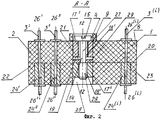
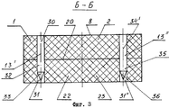
На фиг.1 представлен общий вид электрического соединителя, на фиг.2 - разрез электрического соединителя по А-А, на фиг.3 - разрез электрического соединителя по Б-Б.Figure 1 presents a General view of the electrical connector, figure 2 is a section of an electrical connector according to aa, figure 3 is a section of an electrical connector according to bb.
В корпусе 1 вилки 2 (фиг.1) электрического соединителя выполнены контактные штыри 3', 3''...3(i) первого ряда и контактные штыри 3(j)...3(j+1)...3(k) n-го ряда. В корпусе 1 образовано первое отверстие 4. Внешние основные плоскости 5,6 корпуса 1 параллельны друг другу, а первая плоскость симметрии 7-7 параллельна внешним основным плоскостям 5 и 6. На грани 8 корпуса 1 образован буртик 9 кольцевой формы, внутренняя поверхность 10 и внешняя поверхность 11 которого соосны с первым отверстием 4, ось которого расположена по одну сторону от первой плоскости симметрии 7-7 на второй плоскости симметрии 12-12, перпендикулярной первой плоскости симметрии 7-7. Таким образом буртик 9 расположен по одну сторону от первой плоскости симметрии 7-7. По другую сторону от плоскости симметрии 7-7 расположены первый направляющий штырь 13' и второй направляющий штырь 13'', находящиеся по разные стороны от второй плоскости симметрии 12-12. В электрический соединитель вставлен болт 14, имеющий головку 15 со шлицом 16.In the
В корпусе 1 вилки 2 (фиг.2) заармирована первая втулка 17', в которой выполнено резьбовое отверстие 18'. Между торцом 19 первой втулки 17' и гранью 20 корпуса 1 образован промежуток 21.In the
В корпусе 22 розетки 23 выполнены гнезда 24', 24''...24(i) первого ряда, соответствующего первому ряду контактных штырей 3', 3''...3(i). В корпусе 22 образовано второе отверстие 25 соосное с первым отверстием 4 в корпусе 1. В корпус 22 заармирована вторая втулка 17'' с резьбовым отверстием 18''.Sockets 24 ', 24''... 24 (i) of the first row corresponding to the first row of contact pins 3', 3 '' ... 3 (i) are made in the
Продольные оси 26'-26', 26''-26''...26(i)-26(i) контактных штырей 3', 3''...3(i) и гнезд 24', 24''...24(i) параллельны первой плоскости симметрии 7-7.Longitudinal axes 26'-26 ', 26''-26''... 26 (i) -26 (i) contact pins 3', 3 '' ... 3 (i) and sockets 24 ', 24'' ... 24 (i) are parallel to the first plane of symmetry 7-7.
Болт 14 имеет гладкую часть 27 и резьбовую часть 28. Головка болта 14 расположена внутри буртика 9, гладкая часть 27 входит в резьбовое отверстие 18' первой втулки 17', а резьбовая часть 28 свинчена с резьбовым отверстием 18'' во второй втулке 17''. В промежутке 21 в корпусе 1 на гладкой части 27 установлена запорная шайба 29.The
Первый направляющий штырь 13' (фиг.3) запрессован в корпус 1 вилки 2 своей частью 30 от грани 8 до грани 20 и входит в образованное в корпусе 22 розетки третье отверстие 31' своей частью 32, имеющей конусный наконечник 33. Второй направляющий штырь 13'' запрессован в корпус 1 своей частью 34 и входит в четвертое отверстие 31'' своей частью 35 с конусным наконечником 36.The first guide pin 13 '(Fig. 3) is pressed into the
При соединении вилки 2 с розеткой 23 конусный наконечник 33 первого направляющего штыря 13' входит в третье отверстие 31' в корпусе 22, конусный наконечник 36 второго направляющего штыря 13'' входит в четвертое отверстие 31'', резьбовая часть 28 болта 14 начинает свинчиваться с резьбовым отверстием 18'' во второй втулке 17''. Головка 15 болта 14 опирается на первую втулку 17' и корпус 1 вилки 2 перемещается до тех пор, пока грань 20 корпуса 1 не упрется в грань корпуса 22 розетки 23. При этом контактный штырь 3' соединяется с гнездом 24', контактный штырь 3'' соединяется с гнездом 24'' и далее контактный штырь 3(i) первого ряда штырей соединяется с гнездом 24(i), контактные штыри 3(j)...3(k) n-го ряда штырей соединяются с соответствующими гнездами. Таким образом обеспечивается однозначное соединение электрических цепей посредством электрического соединителя.When connecting the
При отсоединении вилки 2 от розетки 23 резьбовая часть 28 болта 14 опирается на запорную шайбу, которая нажимает на торец 19 первой втулки 17'. В результате вилка 2 выходит из розетки 23.When disconnecting the
Буртик 9 защищает электрические цепи от повреждения при выскальзывании отвертки из шлица 16 болта 14 при операциях соединения или отсоединения вилки 2 с розеткой 23.The
Источники информацииSources of information
1. Авторское свидетельство СССР №657492 кл. H 01 R 13/645. Штепсельный разъем. 1979 г.1. USSR author's certificate No. 657492 class. H 01
2. Патент США №5533909 НКИ 439-381, МКИ H 01 R 13/621. Электрический соединитель. 1996 г.2. US patent No. 5533909 NKI 439-381, MKI H 01
Claims (1)
Priority Applications (1)
| Application Number | Priority Date | Filing Date | Title |
|---|---|---|---|
| RU2004104403/09A RU2261503C1 (en) | 2004-02-17 | 2004-02-17 | Electric coupler |
Applications Claiming Priority (1)
| Application Number | Priority Date | Filing Date | Title |
|---|---|---|---|
| RU2004104403/09A RU2261503C1 (en) | 2004-02-17 | 2004-02-17 | Electric coupler |
Publications (2)
| Publication Number | Publication Date |
|---|---|
| RU2004104403A RU2004104403A (en) | 2005-08-10 |
| RU2261503C1 true RU2261503C1 (en) | 2005-09-27 |
Family
ID=35844361
Family Applications (1)
| Application Number | Title | Priority Date | Filing Date |
|---|---|---|---|
| RU2004104403/09A RU2261503C1 (en) | 2004-02-17 | 2004-02-17 | Electric coupler |
Country Status (1)
| Country | Link |
|---|---|
| RU (1) | RU2261503C1 (en) |
Cited By (1)
| Publication number | Priority date | Publication date | Assignee | Title |
|---|---|---|---|---|
| RU211235U1 (en) * | 2021-10-04 | 2022-05-26 | Акционерное общество "Концерн "Созвездие" | Wire connection device for multiple use |
Citations (2)
| Publication number | Priority date | Publication date | Assignee | Title |
|---|---|---|---|---|
| US4804341A (en) * | 1986-02-14 | 1989-02-14 | Nissan Motor Co., Ltd. | Electrical connector |
| US5533909A (en) * | 1994-03-08 | 1996-07-09 | Yazaki Corporation | Screw clamp type connector with terminal protecting plate |
-
2004
- 2004-02-17 RU RU2004104403/09A patent/RU2261503C1/en not_active IP Right Cessation
Patent Citations (2)
| Publication number | Priority date | Publication date | Assignee | Title |
|---|---|---|---|---|
| US4804341A (en) * | 1986-02-14 | 1989-02-14 | Nissan Motor Co., Ltd. | Electrical connector |
| US5533909A (en) * | 1994-03-08 | 1996-07-09 | Yazaki Corporation | Screw clamp type connector with terminal protecting plate |
Cited By (1)
| Publication number | Priority date | Publication date | Assignee | Title |
|---|---|---|---|---|
| RU211235U1 (en) * | 2021-10-04 | 2022-05-26 | Акционерное общество "Концерн "Созвездие" | Wire connection device for multiple use |
Also Published As
| Publication number | Publication date |
|---|---|
| RU2004104403A (en) | 2005-08-10 |
Similar Documents
| Publication | Publication Date | Title |
|---|---|---|
| US7021964B1 (en) | RJ “F”, modular connector for coaxial cables | |
| US7413478B2 (en) | Electric contact for contacting a protecting conductor with conductive housing | |
| US7766696B2 (en) | Coaxial cable connector assembly | |
| US8579659B2 (en) | SMP electrical connector and connector system | |
| US10135158B2 (en) | Split connector with circular dove tail | |
| US9490582B2 (en) | Insulation body of a plug-in connector | |
| US9768529B2 (en) | Cable connection component | |
| CN108432053A (en) | High speed board connector | |
| CN104466536A (en) | Mixed contact connector | |
| CN107666057A (en) | A kind of circular boundling waterproof inserts type radio frequency connector soon | |
| CN102882053A (en) | Photoelectric mixed connector | |
| KR20140040201A (en) | Coaxial plug-type connector | |
| US4218110A (en) | Connector-to-connector adaptor | |
| CN115995736A (en) | High-performance low-loss VNA connector and use method | |
| RU2698313C1 (en) | Electric plug connection | |
| EP2417670B1 (en) | Low profile compact rf coaxial to planar transmission line interface | |
| CN105071172A (en) | Rectangular high and low frequency mixed connector assembly | |
| CN107577013A (en) | A kind of crossing cabin joints of optical fibre and the joints of optical fibre crossing cabin component | |
| KR101460978B1 (en) | Optical and electrical hybrid connector | |
| RU2261503C1 (en) | Electric coupler | |
| CN207557528U (en) | A kind of crossing cabin optical fiber connector and optical fiber connector crossing cabin component | |
| CN204885729U (en) | Rectangular high and low frequency mixed connector assembly | |
| US9297830B2 (en) | Connector / cable assembly | |
| CN205488747U (en) | Module connector | |
| CN215221114U (en) | Multicore connector and coupling |
Legal Events
| Date | Code | Title | Description |
|---|---|---|---|
| MM4A | The patent is invalid due to non-payment of fees |
Effective date: 20180218 |