RU2251992C1 - Attachment device - Google Patents
Attachment device Download PDFInfo
- Publication number
- RU2251992C1 RU2251992C1 RU2003137670/14A RU2003137670A RU2251992C1 RU 2251992 C1 RU2251992 C1 RU 2251992C1 RU 2003137670/14 A RU2003137670/14 A RU 2003137670/14A RU 2003137670 A RU2003137670 A RU 2003137670A RU 2251992 C1 RU2251992 C1 RU 2251992C1
- Authority
- RU
- Russia
- Prior art keywords
- matrix
- groove
- attachment according
- attachment
- crown
- Prior art date
Links
Images


Landscapes
- Dental Prosthetics (AREA)
Abstract
Description
Изобретение относится к ортопедической стоматологии и может быть использовано для крепления съемных протезов, преимущественно бюгельных.The invention relates to orthopedic dentistry and can be used to attach removable dentures, mainly clasp.
Наиболее распространенным для крепления бюгельных протезов в настоящее время является устройство, содержащее балку, предназначенную для фиксации на ней искусственных зубов, кламмеры, соединенные с балкой и расположенные на вестибулярной и оральной поверхности опорного зуба соответственно (Заявка Германии №4436516, А 61 С 13/267, опубл. 1996 г., Европейская заявка №0134846, А 61 С 13/225, опубл. 1985 г.). Устройства позволяют осуществить быструю и удобную установку съемных мостовидных протезов, а различные конструкции отличаются лишь формой выполнения кламмеров.The most common for fastening clasp prostheses at present is a device containing a beam designed to fix artificial teeth on it, clasps connected to the beam and located on the vestibular and oral surfaces of the abutment tooth, respectively (German Application No. 4436516, A 61 C 13/267 , publ. 1996, European application No. 0134846, A 61 C 13/225, publ. 1985). Devices allow for quick and convenient installation of removable bridges, and various designs differ only in the form of execution of the clasps.
Ограничением устройств являются: распределение жевательного давления на край опорного зуба, что при эксплуатации протеза приводит к нефизиологичной передаче жевательной нагрузки на пародонт.The limitation of the devices are: the distribution of chewing pressure on the edge of the abutment tooth, which during the operation of the prosthesis leads to non-physiological transfer of the chewing load to the periodontium.
Известны балочные аттачмены, выполненные в виде балки - патрицы, закрепляемой на двух опорных зубах, и матрицы для формирования на ней искусственного зуба (“Замковые крепления зубных протезов”, Лебеденко И.Ю., Перегудов, А.Б., Хапилина Т.Э., Москва, Молодая гвардия, 2001 г., стр.18-19, рис.15.). Балки выполняют различной формы. Балки прямоугольного сечения располагают в основном в боковых отделах, а круглого или овального во фронтальном.Known beam attachments made in the form of a beam - a patrician, fixed on two abutment teeth, and a matrix for forming an artificial tooth on it ("Locking dentures", I. Lebedenko, I. Peregudov, A.B., Khapilina T.E. ., Moscow, Young Guard, 2001, pp. 18-19, Fig. 15.). Beams perform various shapes. Beams of rectangular section are located mainly in the lateral sections, and round or oval in the front.
Ограничением устройств являются: необходимость наличия двух или нескольких опорных зубов с промежутком между ними; съемный бюгельный протез, если его выполнить непосредственно на балке, неудобен в установке, а его закрепление непосредственно к балке может приводить к перегрузке опорных зубов или требует довольно часто, один раз в шесть месяцев, перебазировки пластмассового базиса протеза.The limitation of the devices are: the need for two or more supporting teeth with a gap between them; a removable clasp prosthesis, if performed directly on the beam, is inconvenient to install, and fixing it directly to the beam can lead to overload of the abutment teeth or quite often, once every six months, relocate the plastic base of the prosthesis.
Известен внекоронковый неактивируемый рельсовый аттачмен, содержащий матрицу, в которой выполнена канавка, и патрицу, установленную в канавке матрицы (“Замковые крепления зубных протезов”, Лебеденко И.Ю., Перегудов, А.Б., Хапилина Т.Э., Москва, Молодая гвардия, 2001 г., стр.14-15, рис.10).A non-coronal non-activated non-activated rail attachment is known that contains a matrix in which a groove is made and a patrician installed in the matrix groove (“Locking dentures”, I. Lebedenko, Peregudov, AB, Khapilina TE, Moscow, Young Guard, 2001, pp. 14-15, Fig. 10).
В этом устройстве патрица установлена на искусственной коронке опорного зуба. Матрица этих замковых креплений, как правило, выполнена из пластика длительной эластичности и имеет различные уровни ретенции. Такой аттачмен можно отнести к условно неактивируемым, так как с течением времени и потерей ретенции имеется возможность замены матрицы. Внекоронковые неактивируемые рельсовые аттачмены применяются при включенных дефектах; двухсторонних дистально не ограниченных дефектах; в односторонних протезах с трансвериальной стабилизацией.In this device, the patrician is mounted on the artificial crown of the abutment. The matrix of these locks, as a rule, is made of plastic with long elasticity and has different levels of retention. Such an attachment can be classified as conditionally inactive, since over time and the loss of retention there is the possibility of replacing the matrix. Extra-coronal non-activated rail attachments are used with defects included; bilateral distally unlimited defects; in unilateral prostheses with transverbal stabilization.
Ограничением устройств являются: необходимость наличия двух или нескольких опорных зубов с промежутком между ними; съемный бюгельный протез, если его выполнить непосредственно на внекоронковом рельсовом аттачмене из-за прямолинейной формы патрицы, неудобен в установке.The limitation of the devices are: the need for two or more supporting teeth with a gap between them; a removable clasp prosthesis, if it is performed directly on the extra-coronal rail attachment due to the straight form of the patrician, is inconvenient to install.
Наиболее близким к заявленному аттачмену является внутрикорневой неактивируемый рельсовый аттачмен, содержащий матрицу, которая установлена на мезио-дистальной поверхности коронки зуба и в которой выполнена канавка, и патрицу, установленную в канавке матрицы (“Замковые крепления зубных протезов”, Лебеденко И.Ю., Перегудов, А.Б., Хапилина Т.Э., Москва. Молодая гвардия, 2001 г., стр.12-13, рис.8).Closest to the claimed attachment is an intra-root non-activated rail attachment containing a matrix that is installed on the mesio-distal surface of the tooth crown and in which the groove is made, and a patrician installed in the matrix groove (“Locking dentures,” I. Yu. Lebedenko, Peregudov, A.B., Khapilina T.E., Moscow, Young Guard, 2001, pp. 12-13, Fig. 8).
В этом техническом решении канавка обращена в сторону мезиальной поверхности соседнего зуба. Такие замковые крепления представляют собой комплекс штифта или трубки либо прямоугольного, либо клиновидного сечения и выпускаются готовыми блоками. Вдоль поверхности трубки, обращенной в сторону мезиальной поверхности соседнего зуба, выполняется прорезь, так что края матрицы оказываются загнутыми навстречу друг другу. Неактивируемые рельсовые замковые крепления применяются в мостовидных протезах для компенсации непараллельности опорных зубов, используются для присоединения секционных мостовидных протезов, а также в съемных протезах при включенных дефектах во фронтальной области.In this technical solution, the groove faces the mesial surface of the adjacent tooth. Such locking fasteners are a complex of a pin or tube of either a rectangular or wedge-shaped cross section and are available in finished blocks. A slot is made along the surface of the tube facing the mesial surface of the adjacent tooth, so that the edges of the matrix are bent towards each other. Non-activated rail locks are used in bridges to compensate for the imbalance of the abutment teeth, and are used to attach section bridges, as well as in removable prostheses with defects included in the frontal region.
Ограничениями этого технического решения являются:The limitations of this technical solution are:
- неудобство использования такого замкового крепления для съемного бюгельного протеза, поскольку аттачмен может быть выполнен только внутрикоронковым, который имеет прямоугольную или круглую форму матрицы;- the inconvenience of using such a lock for a removable clasp prosthesis, since the attachment can only be made intracoronal, which has a rectangular or round matrix shape;
- невысокая ретенция, т.к. сила трения в этих креплениях не регулируется, а зависит от длины аттачмена;- low retention, because the friction force in these mounts is not adjustable, but depends on the length of the attachment;
- недостаточное восприятие вертикальной нагрузки, т.к. опорная функция в такой конструкции связана с длиной аттачмена;- insufficient perception of the vertical load, because the support function in this design is associated with the length of the attachment;
- невозможность использования такого крепления для опорных искусственных зубов с небольшой высотой, требуется высота коронки не менее 4 мм;- the impossibility of using such a mount for supporting artificial teeth with a small height, a crown height of at least 4 mm is required;
- недостаточно хорошая функция распределения нагрузки и опорная функция, т.к. жевательная нагрузка передается только вдоль продольной оси коронки зуба.- insufficiently good load distribution function and support function, because chewing load is transmitted only along the longitudinal axis of the tooth crown.
Решаемая изобретением задача - повышение технико-эксплуатационных параметров аттачмена при использовании его в съемных бюгельных протезах.The problem solved by the invention is to increase the technical and operational parameters of the attachment when used in removable clasp dentures.
Технический результат, который может быть получен при осуществлении устройства, - обеспечение удобства установки и снятия съемного бюгельного протеза, увеличение силы ретенции, улучшение опорной функции и функции распределения нагрузки, возможность использования при высоте коронки зуба менее 4 мм.The technical result that can be obtained by implementing the device is to ensure ease of installation and removal of a removable clasp prosthesis, an increase in the retention force, an improvement in the support function and the load distribution function, the possibility of using at a tooth crown height of less than 4 mm.
Для решения поставленной задачи с достижением указанного технического результата в известном аттачмене, содержащем матрицу, которая установлена на мезио-дистальной поверхности коронки зуба и в которой выполнена канавка, и патрицу, установленную в канавке матрицы, согласно изобретению аттачмен выполнен внекоронковым, конец матрицы, обращенный к десне, выполнен изогнутым в направлении вестибулярной поверхности коронки зуба, канавка также обращена к вестибулярной поверхности коронки зуба, и, по крайней мере, часть патрицы выполнена с формой, идентичной форме канавки в месте изгиба матрицы.To solve the problem with achieving the specified technical result in a well-known attachment containing a matrix that is installed on the mesio-distal surface of the tooth crown and in which a groove is made, and a patrician installed in the matrix groove, according to the invention, the attachment is made extracrown, the end of the matrix facing the gum is made curved in the direction of the vestibular surface of the tooth crown, the groove is also facing the vestibular surface of the tooth crown, and at least part of the patricia is made with my identical shape of the groove in the matrix bending place.
Возможны дополнительные варианты выполнения устройства, в которых целесообразно, чтобы:Additional embodiments of the device are possible, in which it is advisable that:
- изгиб матрицы был выполнен в форме дуги;- the matrix was bent in the form of an arc;
- край изогнутого конца матрицы был выполнен слегка изогнутым и в направлении к жевательной поверхности коронки зуба;- the edge of the curved end of the matrix was slightly curved and towards the chewing surface of the tooth crown;
- изгиб матрицы выполнен в форме дуги части окружности;- the bend of the matrix is made in the form of an arc of a part of a circle;
- наиболее близкое к десне место изгиба матрицы было расположено в срединной мезио-дистальной плоскости коронки зуба;- the place of the matrix bending closest to the gum was located in the median mesio-distal plane of the tooth crown;
- ширина канавки была выполнена плавно переменной, причем наименьшая ширина - в наиболее низком месте изгиба матрицы;- the width of the groove was smoothly variable, with the smallest width at the lowest point of the bend of the matrix;
- часть матрицы была выполнена параллельной продольной оси коронки зуба, в этой параллельной части матрицы выполнена канавка, стенки которой плавно сопряжены с канавкой в месте изгиба матрицы;- part of the matrix was made parallel to the longitudinal axis of the tooth crown, in this parallel part of the matrix a groove was made, the walls of which are smoothly mated with the groove at the bend of the matrix;
- длина параллельной части матрицы была выбрана меньшей, чем длина изогнутой части матрицы;- the length of the parallel part of the matrix was chosen less than the length of the curved part of the matrix;
- глубина канавки в параллельной части матрицы была постоянна;- the depth of the groove in the parallel part of the matrix was constant;
- глубина канавки в параллельной части матрицы была переменна;- the groove depth in the parallel part of the matrix was variable;
- внутри изгиба матрицы глубина канавки была постоянна;- inside the bend of the matrix, the depth of the groove was constant;
- глубина канавки в месте изгиба была равна глубине канавки в параллельной части матрицы;- the depth of the groove at the bend was equal to the depth of the groove in the parallel part of the matrix;
- в месте изгиба матрицы глубина канавки была переменна;- at the bend of the matrix, the depth of the groove was variable;
- наибольшая глубина канавки была расположена в наиболее близком к десне месте изгиба матрицы;- the greatest depth of the groove was located at the site of the matrix bending closest to the gum;
- противоположный изогнутому в направлении вестибулярной поверхности коронки зуба конец матрицы был выполнен с плавным извивом, который выполнен с возможностью обеспечения S-образной формы в продольном сечении для всей матрицы;- the end of the matrix, which is opposite to the tooth crown crown curved in the direction of the vestibular surface, was made with a smooth twist, which is configured to provide an S-shape in longitudinal section for the entire matrix;
- форма извива была выполнена соответствующей форме жевательной поверхности коронки зуба;- the shape of the twist was made corresponding to the shape of the chewing surface of the tooth crown;
- извив был свободен от канавки;- the twist was free from the groove;
- извив был выполнен с канавкой, которая плавно сопряжена с канавкой в месте изгиба матрицы;- the twist was made with a groove that is smoothly interfaced with the groove at the bend of the matrix;
- стенка канавки матрицы, ближайшая к мезио-дистальной поверхности коронки зуба, была установлена вровень с этой поверхностью;- the matrix groove wall closest to the mesio-distal surface of the tooth crown was installed flush with this surface;
- в патрице со стороны, обращенной к канавке, была выполнена щель;- a gap was made in the patrician from the side facing the groove;
- канавка была выполнена в поперечном сечении прямоугольной;- the groove was made in a rectangular cross-section;
- канавка была выполнена в поперечном сечении полукруглой;- the groove was made in a semicircular cross section;
- канавка была выполнена в поперечном сечении в форме трапеции.- the groove was made in cross section in the form of a trapezoid.
Во втором варианте выполнения устройства в аттачмене, содержащем матрицу, которая установлена на мезио-дистальной поверхности коронки зуба и в которой выполнена канавка, и патрицу, установленную в канавке матрицы, согласно изобретению аттачмен выполнен внекоронковым, канавка обращена к вестибулярной поверхности коронки зуба, дно канавки расположено ортогонально мезио-дистальной плоскости и выполнено в этой плоскости в форме дуги, характеризуемой меньшими радиусами в области канавки матрицы, обращенной к десне, и, по крайней мере, часть патрицы выполнена с формой, идентичной форме области канавки матрицы и дуги, характеризуемой меньшими радиусами.In the second embodiment of the device, in the attachment containing the matrix, which is mounted on the mesio-distal surface of the tooth crown and in which the groove is made, and the patrician installed in the matrix groove, according to the invention, the attachment is made extracrown, the groove faces the vestibular surface of the tooth crown, the bottom of the groove is located orthogonally to the mesio-distal plane and is made in this plane in the form of an arc characterized by smaller radii in the region of the groove of the matrix facing the gum, and at least frequently dummy is formed with a shape identical to the shape of the matrix and the area of the arc grooves, characterized by the smaller radii.
Возможны дополнительные варианты выполнения устройства, в которых целесообразно, чтобы:Additional embodiments of the device are possible, in which it is advisable that:
- форма дуги, характеризуемая меньшими радиусами, была выполнена в виде части окружности;- the shape of the arc, characterized by smaller radii, was made as part of a circle;
- матрица была выполнена с корпусом, выступающим за мезио-дистальную поверхность, выступающая за мезио-дистальную поверхность часть корпуса матрицы выполнена с закругленными углами, причем часть поверхности корпуса сопряжена с частью жевательной поверхности коронки зуба и по форме выполнена ей идентичной;- the matrix was made with the body protruding beyond the mesio-distal surface, the part of the matrix body protruding beyond the mesio-distal surface, made with rounded corners, and part of the surface of the body is paired with part of the chewing surface of the tooth crown and is identical in shape to it;
- дно канавки матрицы было выполнено S-образным, причем извив дна канавки, обращенный к вестибулярной и жевательной поверхности коронки, выполнен с радиусами кривизны, меньшими, чем меньшие радиусы в области канавки матрицы, обращенной к десне.- the bottom of the groove of the matrix was S-shaped, and the curvature of the bottom of the groove facing the vestibular and chewing surface of the crown was made with radii of curvature smaller than the smaller radii in the area of the groove of the matrix facing the gum.
В третьем варианте выполнения устройства в аттачмене, выполненном внутрикоронковым и содержащем матрицу, которая установлена на мезио-дистальной поверхности коронки зуба и в которой выполнена канавка, и патрицу, предназначенную для установки в канавке матрицы, согласно изобретению канавка обращена к вестибулярной поверхности коронки зуба, дно канавки расположено перпендикулярно мезио-дистальной плоскости и выполнено в этой плоскости в форме дуги, характеризуемой меньшими радиусами в области канавки матрицы, обращенной к десне, и, по крайней мере, часть патрицы выполнена с формой, идентичной форме области канавки матрицы и форме дуги, характеризуемой меньшими радиусами, при этом в матрице со стороны мезио-дистальной поверхности зуба выполнен паз для размещения в нем штанги бюгельного протеза, к которой прикреплена патрица.In a third embodiment of the device in an attachment made intracoronal and containing a matrix that is mounted on the mesio-distal surface of the tooth crown and in which a groove is made, and a patricia designed to be installed in the matrix groove, according to the invention, the groove faces the vestibular surface of the tooth crown the grooves are perpendicular to the mesio-distal plane and made in this plane in the form of an arc, characterized by smaller radii in the region of the groove of the matrix facing the gum, and, according to Raina least part of the dummy is formed with a shape identical to the shape of the groove area of the array and shape of an arc, characterized by the smaller radii, wherein the matrix by the mesio-distal tooth surface, a groove for accommodating the rod partial denture, to which is attached patrix.
Возможны дополнительные варианты выполнения устройства, в которых целесообразно, чтобы:Additional embodiments of the device are possible, in which it is advisable that:
- форма дуги, характеризуемой меньшими радиусами, была выполнена в виде части окружности.- the shape of the arc, characterized by smaller radii, was made as part of a circle.
- матрица была выполнена с корпусом, установленным вровень с мезио-дистальной и жевательной поверхностями коронки опорного зуба;- the matrix was made with a body installed flush with the mesio-distal and chewing surfaces of the crown of the abutment tooth;
- дно канавки матрицы было выполнено S-образным, причем извив дна канавки, обращенный к вестибулярной и жевательной поверхности коронки, выполнен с радиусами кривизны, меньшими, чем меньшие радиусы в области канавки матрицы, обращенной к десне;- the bottom of the groove of the matrix was S-shaped, and the curl of the bottom of the groove facing the vestibular and chewing surface of the crown was made with radii of curvature smaller than the smaller radii in the region of the groove of the matrix facing the gum;
- матрица была выполнена в виде вкладки, предназначенной для установки в искусственной коронке зуба;- the matrix was made in the form of tabs intended for installation in an artificial tooth crown;
- матрица была выполнена в виде вкладки, предназначенной для установки в коронковой части естественного зуба.- the matrix was made in the form of tabs intended for installation in the coronal part of a natural tooth.
Особенностью настоящего изобретения является создание комбинированной конструкции аттачмена, в котором использована совокупность функций, выполняемых внутрикоронковыми и внекоронковыми аттачменами, что позволяет объединить все положительные свойства, которые проявляют упомянутые аттачмены по отдельности. По месту же расположения заявленный аттачмен можно отнести к внекоронковым, в которых матрицы или патрицы внекоронковых аттачменов расположены внутри съемного протеза. Подобные экстракоронарные крепления ранее имели пришеечное расположение, что могло вызывать хроническое раздражение десны. Кроме того, ранее экстракоронарные аттачмены оказывали внеосевую нагрузку, которая могла привести к наклону опорного зуба. Внутрикоронковые или интракоронарные аттачмены имеют преимущества в связи с действием нагружающей силы ближе к продольной оси зуба и большей сопротивляемостью к воздействию вертикальных и горизонтальных сил, но являются весьма неудобными для использования в бюгельных съемных протезах. Поэтому была поставлена задача создания внекоронкового или внутрикоронкового аттачмена, свободного от недостатков внутрикоронкового аттачмена, с переносом в устройство тех положительных функций, которые выполняют интракоронарные аттачмены. В то же время для активации внекоронковых рельсовых аттачменов ранее приходилось снабжать матрицы замкового крепления специальными регуляторами, которые позволяли уменьшить ее объем, увеличивая силу ретенции. Однако в целом конструкция с применением специальных регуляторов становится усложненной и имеет достаточно большие габариты. В заявленном техническом решении увеличение силы ротации достигается простыми средствами, что будет показано в дальнейшем.A feature of the present invention is the creation of a combined attachment design, which uses a set of functions performed by intracoronal and extracoronal attachments, which allows you to combine all the positive properties that the mentioned attachments separately. At the same location, the declared attachment can be attributed to extra-coronal, in which the matrices or patrices of extra-coronal attachments are located inside the removable prosthesis. Such extracoronary mounts previously had a cervical location, which could cause chronic gum irritation. In addition, previously extracoronary attachments exerted an off-axis load, which could lead to the inclination of the abutment. Intracoronal or intracoronary attachments have advantages in connection with the action of the loading force closer to the longitudinal axis of the tooth and greater resistance to the effects of vertical and horizontal forces, but are very inconvenient for use in clasp dentures. Therefore, the task was to create an extra-coronal or intracoronal attachment, free from the shortcomings of the intracoronal attachment, with transferring to the device those positive functions that intracoronary attachments perform. At the same time, for the activation of extra-coronal rail attachments, previously, it was necessary to equip the matrix of the lock fastening with special regulators, which made it possible to reduce its volume, increasing the retention force. However, in general, the design using special regulators becomes complicated and has a fairly large size. In the claimed technical solution, an increase in the rotation force is achieved by simple means, which will be shown in the future.
Указанные преимущества, а также особенности настоящего изобретения поясняются лучшими вариантами его выполнения со ссылками на прилагаемые фигуры.These advantages, as well as features of the present invention are illustrated by the best options for its implementation with reference to the accompanying figures.
Фиг.1 изображает заявленную конструкцию внекоронкового аттачмена (вариант I), вид на мезио-дистальную поверхность коронки зуба;Figure 1 depicts the claimed design of the extra-coronal attachment (option I), a view of the mesio-distal surface of the tooth crown;
Фиг.2 - то же, что фиг.1, вид на вестибулярную поверхность коронки зуба;Figure 2 is the same as figure 1, a view of the vestibular surface of the crown of the tooth;
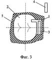
Фиг.3 - то же, что фиг.1, вид на жевательную поверхность;Figure 3 is the same as figure 1, a view of the chewing surface;
Фиг.4 - то же, что фиг.2, с переменной шириной канавки;Figure 4 - the same as figure 2, with a variable width of the groove;
Фиг.5 - то же, что фиг.1, с переменной глубиной канавки;Figure 5 is the same as figure 1, with a variable depth of the groove;
Фиг.6 - то же, что фиг.1, с S-образной формой матрицы и с глубиной канавки, наибольшей в срединной мезио-дистальной плоскости коронки зуба;6 is the same as figure 1, with an S-shaped matrix and with the depth of the groove, the largest in the median mesio-distal plane of the tooth crown;
Фиг.7 - то же, что фиг.6, с выполнением одинаковой по глубине канавки в области изгиба матрицы и в противоположной области извива S-образной матрицы;Fig.7 - the same as Fig.6, with the execution of the same depth grooves in the bending region of the matrix and in the opposite region of the twist of the S-shaped matrix;
Фиг.8 - то же, что фиг.2, с расположением стенки канавки вровень с мезио-дистальной поверхностью коронки и со щелью, выполненной в патрице;Fig.8 is the same as Fig.2, with the location of the groove wall flush with the mesio-distal surface of the crown and with a slit made in the patrician;
Фиг.9 - поперечное сечение матрицы, выполненной с прямоугольной канавкой;Fig.9 is a cross section of a matrix made with a rectangular groove;
Фиг.10 - то же, что фиг.9, с полукруглой канавкой.Figure 10 is the same as figure 9, with a semicircular groove.
Фиг.11 - то же, что фиг.9, с канавкой в форме трапеции.11 is the same as figure 9, with a groove in the shape of a trapezoid.
Фиг.12 - заявленную конструкцию внекоронкового аттачмена (вариант II), вид на мезио-дистальную поверхность коронки зуба;Fig - the claimed design of the extra-coronal attachment (option II), view of the mesio-distal surface of the tooth crown;
Фиг.13 - то же, что фиг.12, вид на вестибулярную поверхность коронки зуба, с закругленными углами корпуса матрицы;Fig.13 is the same as Fig.12, a view of the vestibular surface of the tooth crown, with rounded corners of the matrix body;
Фиг.14 - то же, что фиг.12, вид на жевательную поверхность;Fig.14 is the same as Fig.12, a view of the chewing surface;
Фиг.15 - то же, что фиг.12, с закругленными углами корпуса матрицы и с частью поверхности корпуса матрицы, сопряженной с частью жевательной поверхности коронки зуба;Fig. 15 is the same as Fig. 12, with rounded corners of the matrix body and with a part of the surface of the matrix body mating with a part of the chewing surface of the tooth crown;
Фиг.16 - то же, что фиг.12, с S-образным дном канавки;Fig.16 is the same as Fig.12, with an S-shaped bottom of the groove;
Фиг.17 - заявленную конструкцию внутрикоронкового аттачмена (вариант III), вид на мезио-дистальную поверхность коронки зуба;Fig - the claimed design of the intracoronal attachment (option III), a view of the mesio-distal surface of the tooth crown;
Фиг.18 - то же, что фиг.1, вид на вестибулярную поверхность коронки зуба;Fig. 18 is the same as Fig. 1, a view of the vestibular surface of the tooth crown;
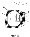
Фиг.19 - то же, что фиг.1, вид на жевательную поверхность.Fig.19 is the same as Fig.1, a view of the chewing surface.
Аттачмен (фиг.1-3) содержит матрицу 1, которая установлена на мезио-дистальной поверхности коронки 2 зуба и в которой выполнена канавка 3. Патрица 4 установлена в канавке 3 матрицы 1 (для наглядности и удобства чтения чертежей патрица 4 на фигурах показана вне канавки 3 матрицы 1 и изображена только часть патрицы 4 с формой, соответствующей изгибу матрицы 1, т.к. оставшаяся часть патрицы 4 может быть выполнена произвольной, с любой формой, удобной для расположения внутри съемного протеза). По месту расположения аттачмен выполнен внекоронковым. Конец матрицы 1, обращенный к десне 5, выполнен плавно изогнутым в направлении вестибулярной поверхности коронки 2. Канавка 3 также обращена к вестибулярной поверхности коронки 2. По крайней мере, часть патрицы 4 выполнена с формой, идентичной форме канавки 3 в месте изгиба матрицы 1.The attachment (Figs. 1-3) contains a
В дополнительных вариантах выполнения изобретения изгиб матрицы 1 выполнен в форме дуги (фиг.1).In additional embodiments of the invention, the bending of the
Кроме того, самый край изогнутого конца матрицы может быть выполнен слегка изогнутым и в направлении к жевательной поверхности коронки 2 зуба (фиг.1, 5-7). Для этого варианта изгиб матрицы 1 может быть выполнен в форме дуги части окружности.In addition, the very edge of the curved end of the matrix can be made slightly curved and towards the chewing surface of the
Наиболее близкое к десне 5 место изгиба матрицы 1 может быть расположено в срединной мезио-дистальной плоскости коронки 2 (фиг.1, 5-7).Closest to the
Ширина канавки 3 может быть выполнена плавно переменной (фиг.4). Наименьшая ширина канавки 3 расположена в наиболее низком месте изгиба матрицы 1 (обращенном к десне 5).The width of the
Часть матрицы 1 выполнена параллельной продольной оси коронки 2 (фиг.1, 5). В этой параллельной части матрицы 1 также выполнена канавка 3. Стенки канавки 3 параллельной части матрицы 1 плавно сопряжены со стенками канавки 3 в месте изгиба матрицы 1. Целесообразно длину параллельной части матрицы 1 выбирать меньшей, чем длина изогнутой части матрицы.Part of the
Глубина канавки 3 в параллельной части матрицы 1 может быть выбрана постоянной (фиг.1). Глубина канавки 3 в параллельной части матрицы 1 может быть выбрана переменной (фиг.5).The depth of the
Кроме того, внутри изгиба матрицы 1 глубина канавки 3 может быть выбрана постоянной (фиг.1). При этом глубина канавки 3 в месте изгиба матрицы 1 может быть равна глубине канавки 3 в параллельной части матрицы 1.In addition, inside the bend of the
В месте изгиба матрицы 1 глубина канавки 3 может быть выбрана переменной (фиг.5, 6). Наибольшая глубина канавки 3 может быть расположена в наиболее близком к десне 5 месте изгиба матрицы 1 (фиг.6).In the place of bending of the
Противоположный изогнутому концу, в направлении вестибулярной поверхности коронки 2, другой конец матрицы 1 может быть выполнен с извивом 6 (фиг.6, 7). Извив 6 выполнен плавным, с возможностью обеспечения S-образной формы в продольном сечении всей матрицы 1. Форма извива 6 может быть выполнена соответствующей (одинаковой по профилю и расположенной вровень с жевательной поверхностью) форме жевательной поверхности коронки 2.Opposite the curved end, in the direction of the vestibular surface of the
Канавка 3 в месте извива 6 может не выполняться. Или извив 6 может быть выполнен с канавкой 3, которая плавно сопряжена с канавкой 3 в месте изгиба матрицы 1.
Стенка канавки 3 матрицы 1, ближайшая к мезио-дистальной поверхности коронки 2, может быть установлена вровень с этой поверхностью (фиг.8).The wall of the
Для придания аттачмену функции активируемости в патрице 4 со стороны, обращенной к канавке 3, выполнена щель 7.To give the attachment the function of activability in
В поперечном сечении канавка 3 может быть выполнена прямоугольной (фиг.9), полукруглой (фиг.10), в форме трапеции (фиг.11).In cross section, the
Работа изобретенного аттачмена описывается следующим образом (фиг.1-3).The work of the invented attachment is described as follows (Fig.1-3).
При установке патрицы 4 съемного бюгельного протеза в матрицу 1 аттачмена за счет того, что она выполнена с изгибом, происходит перераспределение жевательной нагрузки. Наиболее благоприятной для пародонта опорных зубов является нагрузка, по направлению совпадающая с осью коронки 2 зуба, и менее благоприятна постоянная нагрузка, перпендикулярная оси зуба. Так как матрица 1 аттачмена установлена на коронке 2 (подобно внутрикоронковым рельсовым аттачменам) и выполнена заявленной формы, а часть патрицы выполнена с формой, идентичной форме канавки в месте изгиба матрицы, то, как показали испытания, устройство обеспечивает следующие функции: ретенцию, восприятие вертикальной нагрузки (опорная функция), латериальная стабилизация за счет проксимальных стенок аттачмена.When the
Удерживающая функция аттачмена заключается в предохранении протеза от сбрасывания с протезного ложа, выполнение матрицы 1 с изгибом и канавкой 3 обеспечивает стабильное положение протеза. Патрица 4 устанавливается с небольшим натягом в канавке 3 матрицы 1, что позволяет создать удерживающую силу, достаточную для фиксации протеза во время жевательного акта, а с другой стороны, эта удерживающая сила позволяет не повредить пародонт опорных зубов при снятии протеза.The retaining function of the attachment is to protect the prosthesis from dropping from the prosthetic bed, the implementation of the
Опорная функция аттачмена обеспечивает передачу части жевательной нагрузки от базиса протеза к коронке 2 опорного зуба. Заявленный аттачмен - полужесткое или жесткое замковое крепление, которое в силу заявленной формы матрицы 1 и патрицы 4 обладает этой функцией. Опорная функция улучшается, т.к. конструкция исключает наиболее травматичную ротационную и люксационную нагрузки. Кроме того, опорная функция значительно улучшается, т.к. патрица 4 удерживается в матрице 1 не только за счет сил трения, а также за счет изгиба матрицы 1 и выбора соответствующей изгибу формы патрицы 4.The supporting function of the attachment ensures the transfer of part of the chewing load from the basis of the prosthesis to the
За счет того, что конец матрицы, обращенный к десне, выполнен плавно изогнутым в направлении вестибулярной поверхности коронки зуба, протез легко устанавливается, а аттачмен обладает противоопрокидывающей функцией, которая обеспечивает предохранение балансирующей стороны базиса протеза от опрокидывания при нагрузке на рабочую сторону. Изгиб матрицы 1 препятствует движениям базиса протеза в направлении, не совпадающем с путем наложения протеза на протезное ложе.Due to the fact that the end of the matrix facing the gum is smoothly curved in the direction of the vestibular surface of the tooth crown, the prosthesis is easily installed, and the attachment has an anti-tipping function, which protects the balancing side of the base of the prosthesis from overturning under load on the working side. The bending of the
Аттачмен обладает улучшенной направляющей функцией. Направляющая функция аттачмена, подобно рельсовым элементам, обеспечивает определенное положение и направление микродвижений базиса протеза.Attachment has an improved guide function. The guiding function of the attachment, like rail elements, provides a certain position and direction of micromotion of the prosthesis base.
Аттачмен также улучшает функцию распределения нагрузки, которая выражается в передаче жевательной нагрузки на пародонт оставшихся зубов и слизистую оболочку протезного ложа. Как видно из фигур, форма матрицы 1 и патрицы 4 позволяет совершать вертикальное перемещение и небольшую мезио-дистальную ротацию, подобно полулабильным экстра- и интракоронарным замковым креплениям, включающим в себя несколько элементов, например, рельсовый и сферический. Заявленный аттачмен позволяет съемному протезу под действием жевательного давления совершать два рабочих движения. Сначала он перемещается вертикально по направлению к слизистой оболочке, затем совершает огибающее движение по отношению к опорным коронкам 2.Attachment also improves the load distribution function, which is expressed in the transfer of chewing load on the periodontium of the remaining teeth and the mucous membrane of the prosthetic bed. As can be seen from the figures, the shape of the
Другие технические усовершенствования не требуют скрупулезных пояснений и понятны специалистам.Other technical improvements do not require thorough explanations and are understandable to specialists.
Для обеспечения удобства установки бюгельного протеза изгиб матрицы 1 выполнен плавным, в форме дуги. Чтобы улучшить фиксацию протеза с сохранением упомянутых выше положительных качеств, край изогнутого конца матрицы 1 выполнен слегка изогнутым и в направлении к жевательной поверхности коронки 2 зуба. Для обеспечения мезио-дистальной ротации и дополнительного улучшения функции распределения нагрузки изгиб матрицы 1 выполняют в форме дуги части окружности.To ensure ease of installation of the clasp prosthesis, the bending of the
Чтобы улучшить противоопрокидывающую функцию и обеспечить нагрузку, по направлению совпадающую с осью коронки 2, наиболее близкое к десне 5 место изгиба матрицы расположено в срединной мезио-дистальной плоскости коронки 2 зуба.In order to improve the anti-tipping function and ensure the load in the direction coinciding with the axis of the
Для удобства установки протеза ширина канавки 3 выполнена плавно переменной (фиг.4). Для выполнения удерживающей функции наименьшая ширина канавки 3 расположена в наиболее низком месте изгиба матрицы 1.For ease of installation of the prosthesis, the width of the
Для коронок с высотой более 5 мм с целью уменьшения вращательной нагрузки на коронку 2 часть матрицы 1 выполнена параллельной продольной оси коронки 2 (фиг.1, 5). Стенки канавки 3 параллельной части матрицы 1 плавно сопряжены со стенками канавки 3 в месте изгиба матрицы 1. Для выполнения удерживающей функции целесообразно длину параллельной продольной оси коронки 2 части матрицы 1 выбирать меньшей, чем длина изогнутой части матрицы.For crowns with a height of more than 5 mm in order to reduce the rotational load on the
Глубина канавки 3 в параллельной части матрицы 1 может быть выбрана постоянной (фиг.1) или переменной (фиг.5) в зависимости от необходимости увеличения или уменьшения силы трения для конкретных форм протезирования. В частном случае внутри изгиба матрицы 1 глубина канавки 3 может быть выбрана постоянной (фиг.1). При этом глубина канавки 3 в месте изгиба матрицы 1 может быть равна глубине канавки 3 в параллельной части матрицы 1.The depth of the
В месте изгиба матрицы 1 глубина канавки 3 может быть выбрана переменной (фиг.5, 6). Для улучшения удерживающей функции наибольшая глубина канавки 3 расположена в наиболее близком к десне 5 месте изгиба матрицы 1 (фиг.6).In the place of bending of the
Для увеличения площади поверхности, закрепляемой в коронке 2, и упрощения установки бюгельного протеза противоположный изогнутому в направлении вестибулярной поверхности коронки 2 конец матрицы 1 может быть выполнен с извивом 6 (фиг.6, 7). Извив 6 выполнен плавным, с возможностью обеспечения S-образной формы в продольном сечении всей матрицы 1. Для удобства пользования форма извива 6 соответствует форме жевательной поверхности коронки 2.To increase the surface area fixed in the
В зависимости от конкретных коронок 2 зубов (резцов или клыков) канавка 3 в месте извива 6 может не выполняться (фиг.6). Или извив 6 может быть выполнен с канавкой 3, которая плавно сопряжена с канавкой 3 в месте изгиба матрицы 1 (фиг.7).Depending on the
Для уменьшения габаритов выступающей части аттачмена, а также для улучшения опорной функции стенка канавки 3 матрицы 1, ближайшая к мезио-дистальной поверхности коронки 2, может быть установлена вровень с этой поверхностью (фиг.8).To reduce the dimensions of the protruding part of the attachment, as well as to improve the support function, the wall of the
Для создания активируемого аттачмена в патрице 4 со стороны, обращенной к канавке 3, выполнена щель 7 (фиг.7 или 8). Для того чтобы увеличить трение патрицы 4 о стенки матрицы 1, необходимо расширить эту щель 7 активатором. Чтобы было удобно устанавливать активируемые аттачмены с верхнего положения в нижнее, ширину канавки 3 следует выполнять плавно переменной (фиг.4) с уменьшением ширины канавки 3 в направлении наиболее низкого места изгиба матрицы 1.To create an activated attachment in the patrician 4 from the side facing the
В зависимости от необходимости использования (увеличения/уменьшения) сил поперечного трения о дно канавки 3 патрицы 4 или продольного трения о стенки канавки 3 она в поперечном сечении может быть выполнена прямоугольной формы (фиг.9), полукруглой формы (фиг.10), в форме трапеции (фиг.11).Depending on the need to use (increase / decrease) the forces of transverse friction on the bottom of the
Специалистам понятно, что описанный выше вариант выполнения изобретения описывает, по крайней мере, основные случаи, которые могут использоваться при индивидуальном протезировании. И данный вариант не исключает других усовершенствований, известных из уровня техники, которые могут быть применены в реальных условиях при протезировании конкретных пациентов.Those skilled in the art will understand that the above-described embodiment of the invention describes at least the basic cases that can be used with individual prosthetics. And this option does not exclude other improvements known from the prior art, which can be applied in real conditions when prosthetics of specific patients.
Однако с целью упрощения технологии изготовления самого аттачмена и использования его в большинстве случаев клинической практики может быть рекомендовано изготовление блоков аттачмена различных типоразмеров в серийном производстве.However, in order to simplify the manufacturing technology of the attachment itself and use it in most cases of clinical practice, the manufacture of attachment blocks of various sizes in serial production may be recommended.
Такой атгачмен (фиг.12-15) содержит матрицу 1, которая установлена на мезио-дистальной поверхности коронки 2 зуба и в которой выполнена канавка 3. Патрица 4 предназначена для установки в канавке 3 матрицы 1 (на фиг.12-15 для наглядности показана вне канавки). Аттачмен выполнен внекоронковым. Канавка 3 обращена к вестибулярной поверхности коронки 2. Дно канавки 3 расположено ортогонально мезио-дистальной плоскости. Дно канавки 3 выполнено в мезио-дистальной плоскости в форме дуги (на фиг.12 дно канавки показано пунктирной линией), характеризуемой меньшими радиусами в области канавки 3 матрицы 1, обращенной к десне 5. По крайней мере, часть патрицы 4 выполнена с формой, идентичной форме области канавки 3 матрицы 1 и дуги, характеризуемой меньшими радиусами.Such an athachman (Figs. 12-15) contains a
Для обеспечения достальной ротации форма дуги, характеризуемая меньшими радиусами, выполнена в виде части окружности (фиг.1).To ensure adequate rotation, the shape of the arc, characterized by smaller radii, is made in the form of a part of a circle (Fig. 1).
Матрица 1 выполнена с корпусом, выступающим за мезио-дистальную поверхность (фиг.13, 14). Выступающая за мезио-дистальную поверхность часть корпуса матрицы 1 выполнена с закругленными углами (фиг.13-14). Часть поверхности корпуса матрицы 1 сопряжена с частью жевательной поверхности коронки 2 и по форме выполнена ей идентичной (фиг.15).
Дно канавки 3 матрицы 1 может быть выполнено S-образным (фиг.16). Извив 6 дна канавки 3, обращенный к вестибулярной и жевательной поверхности коронки 2, выполнен с радиусами кривизны, меньшими, чем меньшие радиусы в области канавки 3 матрицы, обращенной к десне 5.The bottom of the
Специалистам понятно, что при работе аттачмена по второму варианту он выполняет все вышеописанные функции при работе аттачмена по первому варианту. Однако если технология соединения аттачмена по первому варианту требует достаточно сложного его монтажа, например, приклеиванием боковой стороны S-образной матрицы 1 к коронке 2, или изготовления в коронке 2 соответствующих посадочных мест, или выполнения аттачмена совместно с коронкой по выплавляемым моделям (с индивидуальным подбором размеров и форм для конкретного зуба пациента), то для второго варианта выполнения аттачмена тот может быть изготовлен различных типоразмеров для всевозможных типов и видов коронок 2 опорных зубов. В случае необходимости корпус матрицы 1 может быть выполнен каплеобразным или в виде шарообразной части, в виде эллипсоидообразной части, в виде части параболоида и любой другой формы с закругленными углами корпуса. Закругление углов наружной части корпуса матрицы 1 обеспечивает исключение застревания пищи при выполнении жевательной функции, одновременно улучшает внешний вид аттачмена и более скорое привыкание пациента к установленному инородному предмету. С другой стороны, как видно из фиг.12-15, второй вариант позволяет увеличить площадь продольных стенок канавки 3 матрицы 1, что позволяет дополнительно улучшить удерживающую функцию аттачмена.Specialists understand that when the attachment works according to the second variant, it performs all the functions described above when the attachment works according to the first variant. However, if the attachment attachment technology according to the first embodiment requires its rather complicated installation, for example, by gluing the side of the S-shaped
Кроме того, чтобы матрицу 1 не было видно со стороны жевательной поверхности опорного зуба, для внекоронковых вариантов исполнения она может быть установлена в ниже жевательной поверхности с мезио-дистальной стороны.In addition, so that the
Поскольку патрица 4 устанавливается в матрицу 1 через ее поверхность, обращенную к жевательной поверхности коронки 2 опорного зуба, то отсутствуют какие-либо препятствия для изготовления аттачмена по третьему варианту, в котором он выполнен внутрикоронковым.Since the patrician 4 is installed in the
В третьем варианте выполнения устройства (фиг.17-19) аттачмен выполнен внутрикоронковым и содержит матрицу 1. Матрица 1 установлена на мезио-дистальной поверхности естественного зуба или искусственной коронки 2. В матрице 1 выполнена канавка 3. Патрица 4 предназначена для установки в канавке 3 матрицы 1. Канавка обращена к вестибулярной поверхности коронки 2 зуба. Дно канавки 3 расположено перпендикулярно мезио-дистальной плоскости и выполнено в этой плоскости в форме дуги, характеризуемой меньшими радиусами в области канавки 3 матрицы 1, обращенной к десне 5. По крайней мере, часть патрицы 4 выполнена с формой, идентичной форме области канавки 3 матрицы и форме дуги, характеризуемой меньшими радиусами. В матрице 1 со стороны мезио-дистальной поверхности зуба выполнен паз 8 для размещения в нем штанги 9 бюгельного протеза, к которой прикреплена патрица 4.In the third embodiment of the device (Figs. 17-19), the attachment is made intracoronary and contains a
Так же как во втором варианте форма дуги, характеризуемой меньшими радиусами, может быть выполнена в виде части окружности (фиг.17).As in the second embodiment, the shape of the arc, characterized by smaller radii, can be made in the form of a part of a circle (Fig.17).
Матрица может быть выполнена с корпусом, установленным вровень с мезио-дистальной и жевательной поверхностями коронки 2 опорного зуба (фиг.18, 19).The matrix can be made with a housing installed flush with the mesio-distal and chewing surfaces of the
Дно канавки матрицы 1 может быть выполнено S-образным. Извив 6 дна канавки 3 обращен к вестибулярной и жевательной поверхностям коронки 2 и выполнен с радиусами кривизны, меньшими, чем меньшие радиусы в области канавки 3 матрицы 1, обращенной к десне 5.The bottom of the groove of the
Матрица может быть выполнена в виде вкладки (фиг.17-19), предназначенной для установки в искусственной коронке зуба или предназначенной для установки в коронковой части естественного зуба. Это позволяет изготавливать внутрикоронковые вкладки различных типоразмеров в серийном производстве.The matrix can be made in the form of a tab (Fig.17-19), designed to be installed in an artificial tooth crown or designed to be installed in the crown part of a natural tooth. This allows you to produce vnutrikoronkovye tabs of various sizes in serial production.
Специалистам понятно, что при работе аттачмена по третьему варианту он выполняет все вышеописанные функции при работе аттачмена по первому варианту. Преимуществом этого аттачмена перед первым и вторым вариантами является отсутствие выступающих частей корпуса матрицы 1 за габариты коронки 2 опорного зуба. При использовании в бюгельных протезах описанные выше конструкции аттачмена могут быть использованы совместно с кламмерами для улучшения фиксации протезов.Specialists understand that when the attachment works according to the third variant, it performs all the functions described above when the attachment works according to the first variant. The advantage of this attachment over the first and second options is the absence of protruding parts of the housing of the
Наиболее успешно заявленные варианты аттачмена могут быть промышленно использованы в ортопедической стоматологии для крепления съемных бюгельных протезов, верхней и нижней челюсти.The most successfully declared attachment variants can be industrially used in orthopedic dentistry for fastening removable clasp prostheses, upper and lower jaw.
Claims (33)
Priority Applications (1)
| Application Number | Priority Date | Filing Date | Title |
|---|---|---|---|
| RU2003137670/14A RU2251992C1 (en) | 2003-12-29 | 2003-12-29 | Attachment device |
Applications Claiming Priority (1)
| Application Number | Priority Date | Filing Date | Title |
|---|---|---|---|
| RU2003137670/14A RU2251992C1 (en) | 2003-12-29 | 2003-12-29 | Attachment device |
Publications (1)
| Publication Number | Publication Date |
|---|---|
| RU2251992C1 true RU2251992C1 (en) | 2005-05-20 |
Family
ID=35820459
Family Applications (1)
| Application Number | Title | Priority Date | Filing Date |
|---|---|---|---|
| RU2003137670/14A RU2251992C1 (en) | 2003-12-29 | 2003-12-29 | Attachment device |
Country Status (1)
| Country | Link |
|---|---|
| RU (1) | RU2251992C1 (en) |
-
2003
- 2003-12-29 RU RU2003137670/14A patent/RU2251992C1/en not_active IP Right Cessation
Non-Patent Citations (1)
| Title |
|---|
| ЖУЛЕВ Е.Н., Частичные съемные протезы, из-во Нижний Новгород, 2000, стр.131-143. * |
Similar Documents
| Publication | Publication Date | Title |
|---|---|---|
| US10231802B2 (en) | Customized orthodontic appliance and method | |
| US5674069A (en) | Customized dental abutment | |
| US4698017A (en) | Orthodontic brackets | |
| BRPI0621022A2 (en) | fully adjustable bracket system | |
| AU713845B2 (en) | Customized dental abutment | |
| JP2015058356A (en) | Oral appliance, system and method for solving class iii problems of mandibular prognathism | |
| NZ545973A (en) | Dental appliance | |
| Vig et al. | Hybrid appliances: a component approach to dentofacial orthopedics | |
| WO2007021468A2 (en) | Orthodontic devices and methods | |
| Jain et al. | Attachment-retained unilateral Distal Extension (Kennedy’s class II modification I) Cast partial Denture | |
| CN108601633B (en) | Tongue face orthodontic appliance | |
| KR101476698B1 (en) | The prosthetic components and thereof connection method | |
| BR112018008353B1 (en) | self-connecting bracket | |
| US4580975A (en) | Set of premanufactured positioners for the final treatment in the orthodontic and jaw orthopedic tooth alignment | |
| CN114010347A (en) | Self-fixing type individual lower jaw retainer and construction method thereof | |
| Hilgers | Hyperefficient orthodontic treatment using tandem mechanics | |
| RU2251992C1 (en) | Attachment device | |
| Camacho et al. | Behavior of mandibular canines as abutment teeth and indirect retainers in Kennedy class II Removable Partial Denture Prosthesis | |
| Siatkowski | Optimal orthodontic space closure in adult patients | |
| JP4157129B2 (en) | Customized dental abutment | |
| JP2021527493A (en) | Methods of orthodontic treatment, how to use pearls as holding elements for orthodontic appliances, and pearls for orthodontic treatment | |
| JP2007244890A (en) | Customized dental abutments | |
| RU2251993C1 (en) | Device for fixing clasp dental prosthesis | |
| Javid et al. | The removable partial denture as a periodontal prosthesis | |
| Zinner | Locking types of semiprecision attachments |
Legal Events
| Date | Code | Title | Description |
|---|---|---|---|
| MM4A | The patent is invalid due to non-payment of fees |
Effective date: 20051230 |
|
| NF4A | Reinstatement of patent | ||
| MM4A | The patent is invalid due to non-payment of fees |
Effective date: 20071230 |