RU2249744C2 - Valve at adjustable deformation of ball - Google Patents
Valve at adjustable deformation of ball Download PDFInfo
- Publication number
- RU2249744C2 RU2249744C2 RU2000114630/06A RU2000114630A RU2249744C2 RU 2249744 C2 RU2249744 C2 RU 2249744C2 RU 2000114630/06 A RU2000114630/06 A RU 2000114630/06A RU 2000114630 A RU2000114630 A RU 2000114630A RU 2249744 C2 RU2249744 C2 RU 2249744C2
- Authority
- RU
- Russia
- Prior art keywords
- shutter
- grooves
- ball
- valve
- gate
- Prior art date
Links
- 239000012530 fluid Substances 0.000 claims abstract description 12
- 230000001681 protective effect Effects 0.000 claims abstract description 9
- 238000007789 sealing Methods 0.000 claims description 7
- 238000004519 manufacturing process Methods 0.000 abstract description 3
- 230000000694 effects Effects 0.000 abstract description 2
- 239000000126 substance Substances 0.000 abstract description 2
- 239000002184 metal Substances 0.000 description 6
- 230000005489 elastic deformation Effects 0.000 description 3
- 239000000463 material Substances 0.000 description 3
- 238000000034 method Methods 0.000 description 3
- 229920001169 thermoplastic Polymers 0.000 description 3
- 239000004416 thermosoftening plastic Substances 0.000 description 3
- 238000006073 displacement reaction Methods 0.000 description 2
- 235000001674 Agaricus brunnescens Nutrition 0.000 description 1
- 239000010754 BS 2869 Class F Substances 0.000 description 1
- 239000004215 Carbon black (E152) Substances 0.000 description 1
- 229920002449 FKM Polymers 0.000 description 1
- IOVCWXUNBOPUCH-UHFFFAOYSA-M Nitrite anion Chemical compound [O-]N=O IOVCWXUNBOPUCH-UHFFFAOYSA-M 0.000 description 1
- 239000004677 Nylon Substances 0.000 description 1
- 239000000956 alloy Substances 0.000 description 1
- 229910045601 alloy Inorganic materials 0.000 description 1
- 238000000576 coating method Methods 0.000 description 1
- 239000002131 composite material Substances 0.000 description 1
- 238000010276 construction Methods 0.000 description 1
- 238000010586 diagram Methods 0.000 description 1
- 238000005516 engineering process Methods 0.000 description 1
- 238000002474 experimental method Methods 0.000 description 1
- 238000010438 heat treatment Methods 0.000 description 1
- 238000007749 high velocity oxygen fuel spraying Methods 0.000 description 1
- 229930195733 hydrocarbon Natural products 0.000 description 1
- 150000002430 hydrocarbons Chemical class 0.000 description 1
- 238000009434 installation Methods 0.000 description 1
- 238000003754 machining Methods 0.000 description 1
- 229920001778 nylon Polymers 0.000 description 1
- 239000003921 oil Substances 0.000 description 1
- 239000002245 particle Substances 0.000 description 1
- 230000002093 peripheral effect Effects 0.000 description 1
- 239000004033 plastic Substances 0.000 description 1
- 229920003023 plastic Polymers 0.000 description 1
- -1 polytetrafluoroethylene Polymers 0.000 description 1
- 229920001343 polytetrafluoroethylene Polymers 0.000 description 1
- 239000004810 polytetrafluoroethylene Substances 0.000 description 1
- 238000010248 power generation Methods 0.000 description 1
- 230000003746 surface roughness Effects 0.000 description 1
- XLYOFNOQVPJJNP-UHFFFAOYSA-N water Substances O XLYOFNOQVPJJNP-UHFFFAOYSA-N 0.000 description 1
- 238000003466 welding Methods 0.000 description 1
Images

Classifications
-
- F—MECHANICAL ENGINEERING; LIGHTING; HEATING; WEAPONS; BLASTING
- F16—ENGINEERING ELEMENTS AND UNITS; GENERAL MEASURES FOR PRODUCING AND MAINTAINING EFFECTIVE FUNCTIONING OF MACHINES OR INSTALLATIONS; THERMAL INSULATION IN GENERAL
- F16K—VALVES; TAPS; COCKS; ACTUATING-FLOATS; DEVICES FOR VENTING OR AERATING
- F16K5/00—Plug valves; Taps or cocks comprising only cut-off apparatus having at least one of the sealing faces shaped as a more or less complete surface of a solid of revolution, the opening and closing movement being predominantly rotary
- F16K5/06—Plug valves; Taps or cocks comprising only cut-off apparatus having at least one of the sealing faces shaped as a more or less complete surface of a solid of revolution, the opening and closing movement being predominantly rotary with plugs having spherical surfaces; Packings therefor
- F16K5/0663—Packings
- F16K5/0684—Packings on the plug
Landscapes
- Engineering & Computer Science (AREA)
- General Engineering & Computer Science (AREA)
- Mechanical Engineering (AREA)
- Taps Or Cocks (AREA)
- Fuel-Injection Apparatus (AREA)
Abstract
Description
Настоящее изобретение относится к клапану, имеющему шарик с регулируемой деформацией.The present invention relates to a valve having an adjustable deformation ball.
Шаровые клапаны представляют собой устройства для перекрытия подачи текучей рабочей среды, которые находят широкое применение в самых разнообразных процессах во всех областях техники. Их используют, например, в системах транспортирования воды, нефтепродуктов и газа, в установках получения углеводородов, на химических и нефтехимических заводах, а также в системах производства электроэнергии.Ball valves are devices for shutting off the flow of fluid, which are widely used in a wide variety of processes in all areas of technology. They are used, for example, in transportation systems for water, oil products and gas, in hydrocarbon production plants, in chemical and petrochemical plants, as well as in power generation systems.
Следует также заметить, что шаровые клапаны выпускаются и могут применяться с самыми разными размерами и при давлениях до сотен бар.It should also be noted that ball valves are available and can be used with a wide variety of sizes and pressures up to hundreds of bars.
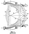
В подобных запорных устройствах, или шаровых клапанах (например, в шаровом клапане, описанном в патенте США №743511, 1903 г.), гидравлическое уплотнение имеет место между шариком и двумя седлами, каждое из которых снабжено круглым вкладышем из деформируемого материала, зажатым между двумя металлическими поверхностями. Указанный шаровой клапан, описанный в патенте США №743511, изображен на фиг.1 и 2.In such shut-off devices, or ball valves (for example, in a ball valve described in US Pat. metal surfaces. The specified ball valve described in US patent No. 743511, shown in figures 1 and 2.
Назначение вкладышей состоит в том, чтобы их собственные деформации уравновесили упругие деформации, незначительные геометрические погрешности и шероховатость, всегда присутствующие на поверхности шарика.The purpose of the liners is to have their own deformations balance the elastic deformations, slight geometric errors and roughness, always present on the surface of the ball.
Как правило, усилие, необходимое для сплющивания вкладыша, а следовательно, и для создания уплотнения, формируется, как показано на Фиг.1 применительно к одному из известных шаровых клапанов, в очень незначительной степени за счет системы пружин (Fm) и главным образом - за счет давления, с которым указанная текучая среда воздействует на седло (Fs).As a rule, the force required to flatten the liner, and therefore to create a seal, is formed, as shown in Fig. 1 with respect to one of the known ball valves, to a very small extent due to the system of springs (Fm) and mainly for the pressure count with which said fluid acts on the seat (Fs).
Вкладыши изготавливают обычно из эластомерных (нитриты, витон и пр.) или термопластичных (политетрафторэтилен, нейлон и пр.) материалов, способных обеспечить наилучшие эксплуатационные характеристики (имеется в виду надежное уплотнение) до тех пор, пока условия работы не становятся особо тяжелыми.Inserts are usually made of elastomeric (nitrite, viton, etc.) or thermoplastic (polytetrafluoroethylene, nylon, etc.) materials that can provide the best performance (meaning reliable sealing) until the operating conditions become especially difficult.
В качестве примера таких тяжелых и ограничивающих условий можно назвать те, которые могут явиться следствием использования особо "загрязненных" текучих сред, увлекающих за собой абразивные частицы. Еще один пример затрудненной работы - необходимость эксплуатации клапана в течение длительного времени в частично открытом положении, когда циркулирующая с высокой скоростью текучая среда с силой трется о вкладыш, либо наличие высоких температур.As an example of such difficult and limiting conditions, we can name those that may result from the use of particularly "contaminated" fluids that entrain abrasive particles. Another example of difficult work is the need to operate the valve for a long time in a partially open position, when the fluid circulating at a high speed rubs against the liner with force, or the presence of high temperatures.
В этих случаях, когда использование эластомерных или термопластичных вкладышей становится опасным и не может быть гарантирована требуемая долговечность системы по прошествии некоторого времени, приходится пользоваться уплотнительными элементами, выполненными целиком из металла.In these cases, when the use of elastomeric or thermoplastic liners becomes dangerous and the required durability of the system cannot be guaranteed after some time has passed, it is necessary to use sealing elements made entirely of metal.
Для этой цели предусматривают упрочнение металлических поверхностей седел клапана, которые служат для создания уплотнения и на которых происходит взаимное скольжение, путем термообработки материала-основы. Согласно другому способу, для этих поверхностей можно предусмотреть покрытия из твердого сплава, получаемые навариванием или другими, более прогрессивными методами (напр., с использованием плазмы, HVOF и т.д.).For this purpose, hardening of the metal surfaces of the valve seats is provided, which serve to create a seal and on which mutual sliding occurs by heat treatment of the base material. According to another method, for these surfaces it is possible to provide coatings of hard alloy obtained by welding or by other, more advanced methods (eg, using plasma, HVOF, etc.).
В этих клапанах, где отсутствует возможность создания надежного уплотнения благодаря упругой деформации вкладыша, приходится выполнять исключительно точную механическую обработку соприкасающихся друг с другом поверхностей седел и шарика с тем, чтобы свести к минимуму имеющиеся геометрические погрешности и шероховатость поверхности.In these valves, where there is no possibility of creating a reliable seal due to the elastic deformation of the liner, it is necessary to perform extremely precise machining of the surfaces of the seats and the ball in contact with each other in order to minimize the existing geometric errors and surface roughness.
На той же Фиг.1 можно видеть, что, когда на закрытый клапан действует давление (р), деформирование шарика происходит неравномерно, поскольку его конфигурация не является осесимметричной. По сути дела, линии действия сил, обусловленные его напряженным состоянием, проходят через шарик в направлении от колпачка (а), на который действует указанное давление, к опорным поверхностям двух ступиц (b), а точки шарика, относящиеся к окружности контакта с седлом (d), неравномерно смещаются от (d) к кривой (е), в то время как наружная поверхность шарика принимает форму (g), а канал для прохода текучей среды - форму (f) (см. пунктирные линии на Фиг.1).In the same FIG. 1, it can be seen that when pressure (p) acts on the closed valve, the deformation of the ball occurs unevenly, since its configuration is not axisymmetric. In fact, the lines of action of the forces, due to its stressed state, pass through the ball in the direction from the cap (a), on which the indicated pressure acts, to the supporting surfaces of the two hubs (b), and the points of the ball related to the circle of contact with the saddle ( d) are unevenly shifted from (d) to curve (e), while the outer surface of the ball takes the form (g), and the channel for the passage of the fluid takes the form (f) (see dashed lines in FIG. 1).
Наблюдение за работой клапана в рассмотренном режиме воздействия давления дает возможность заметить, что жесткость шарика намного больше в двух зонах, верхней и нижней, прилегающих к ступицам (b), нежели в средней зоне, которая оказывается более упругой из-за наличия канала для прохода текучей среды с диаметром Ф0.Observation of the valve operation in the considered pressure exposure mode makes it possible to note that the stiffness of the ball is much greater in two zones, upper and lower, adjacent to the hubs (b), rather than in the middle zone, which is more elastic due to the presence of a channel for the passage of fluid medium with a diameter of f 0 .
Совершенно очевидно, что деформация шарика будет тем большей, чем больше рабочее давление (р).It is obvious that the deformation of the ball will be greater, the greater the working pressure (p).
С другой стороны, чем больше деформация окружности контакта от (d) до (е) отличается между отдельными точками, тем проблематичней становится поддержание контакта между металлическими поверхностями кольцевого седла и шарика или, говоря точнее, контактного давления между седлом и шариком, что могло бы гарантировать надежное уплотнение по всей окружности в 360°.On the other hand, the greater the deformation of the contact circle from (d) to (e) between the individual points, the more problematic it becomes to maintain contact between the metal surfaces of the annular seat and the ball or, more precisely, the contact pressure between the seat and the ball, which could guarantee reliable seal around the entire circumference of 360 °.
Для устранения этого явления обычно прибегают к повышению жесткости шарика или, другими словами, сохраняя те же размеры канала (диаметр Ф0), увеличивают его наружный диаметр (Ф1). Это ведет, однако, к возрастанию размеров, веса и стоимости клапана, не принося сколько-нибудь существенного выигрыша в конструкции и качестве работы.To eliminate this phenomenon, they usually resort to increasing the stiffness of the ball or, in other words, while maintaining the same channel dimensions (diameter Ф 0 ), increase its outer diameter (Ф 1 ). This, however, leads to an increase in the size, weight and cost of the valve, without bringing any significant gain in design and quality of work.
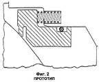
Предпринимались и иные попытки различными способами улучшить работу шаровых клапанов. Так, например, пытались устранить имеющиеся недостатки путем повышения деформируемости седел в соответствии с их напряженным состоянием, то есть так, чтобы они могли более точно повторять деформации шарика под действием усилия со стороны пружин (Fm) и давления (Fs), как показано на Фиг.2, иллюстрирующей один из вариантов выполнения известного устройства.Other attempts have been made in various ways to improve the operation of ball valves. So, for example, they tried to eliminate the existing disadvantages by increasing the deformability of the seats in accordance with their stressed state, that is, so that they could more accurately repeat the ball deformations under the action of the force from the springs (Fm) and pressure (Fs), as shown in FIG. .2 illustrating one embodiment of the known device.
Однако и в этом случае, как показали расчеты, сопровождавшиеся соответствующими экспериментами, подобные меры дают лишь весьма посредственные результаты, не позволяющие эффективно решить имеющиеся проблемы.However, even in this case, as shown by calculations accompanied by the corresponding experiments, such measures give only very mediocre results that do not allow solving the existing problems effectively.
Из авторского свидетельства SU 1638407 (кл. F 16 К 5/06, 30.03.1991 г.) известен шаровой клапан с регулируемой деформацией шарика, предназначенный для перекрытия подачи текучей среды. Данный клапан содержит наружный защитный корпус, внутри которого размещен затвор с возможностью перемещения между закрытым и открытым положениями клапана. Затвор взаимодействует с одним или большим числом седел и обеспечивает получение средств уплотнения относительно защитного корпуса и затвора. На сферических участках затвора, расположенных на уровне указанных седел по отношению к зоне действия давления, имеются зоны деформации, выполненные в виде полостей переменного сечения с концентрическим отверстием. Указанные полости решают проблему неравномерной деформации шарика лишь отчасти, поскольку не увеличивают податливость самых жестких его зон, т.е. верхней и нижней прилегающих к ступицам зон шарика. В результате, на указанные верхнюю и нижнюю зоны шарика давление рабочей среды будет действовать слабее, чем на средние зоны, и вызывать тем самым неравномерную деформацию шарика, которая может привести к нарушению герметичности клапана. Кроме того, выполнение указанных полостей в теле шарика связано с увеличением временных и материальных затрат на его изготовление, а сами полости уменьшают прочность клапана в зоне действия максимальных давлений рабочей среды.From the copyright certificate SU 1638407 (class F 16 K 5/06, 03/30/1991) a ball valve with adjustable deformation of the ball, designed to shut off the fluid supply, is known. This valve contains an external protective housing, inside of which a shutter is placed with the possibility of movement between the closed and open positions of the valve. The shutter interacts with one or more seats and provides a means of sealing relative to the protective housing and shutter. On the spherical sections of the valve located at the level of these seats with respect to the pressure zone, there are deformation zones made in the form of cavities of variable section with a concentric hole. These cavities solve the problem of uneven deformation of the ball only partially, since they do not increase the compliance of its most rigid zones, i.e. the upper and lower adjacent to the hub zones of the ball. As a result, the pressure of the working medium on the indicated upper and lower zones of the ball will be weaker than on the middle zones, and thereby cause uneven deformation of the ball, which can lead to a violation of the valve tightness. In addition, the implementation of these cavities in the body of the ball is associated with an increase in time and material costs for its manufacture, and the cavities themselves reduce the strength of the valve in the area of maximum pressure of the working medium.
Таким образом, задачей изобретения является создание такой конструкции шарового клапана, которая позволила бы добиться исключительно герметичного уплотнения даже при воздействии на клапан очень высоких давлений, а сам клапан при его несложной конструкции и умеренной цене полностью отвечал бы требованиям надежной эксплуатации и герметичности.Thus, the object of the invention is to provide a ball valve design that would allow an extremely tight seal even when the valve is exposed to very high pressures, and the valve itself, with its simple design and reasonable price, would fully meet the requirements for reliable operation and tightness.
Решение поставленной задачи обеспечивается созданием шарового клапана с регулируемой деформацией шарика для перекрытия подачи текучей среды, содержащего наружный защитный корпус, внутри которого размещен затвор с возможностью перемещения между закрытым и открытым положениями клапана, причем затвор взаимодействует с одним или большим числом седел и обеспечивает получение средств уплотнения относительно защитного корпуса и затвора, а на сферических участках затвора, расположенных по отношению к зоне действия давления за указанными седлами, имеются зоны деформации, при этом в указанном клапане зоны деформации образованы посредством канавок, выполненных на поверхностных областях затвора, соответствующих указанным сферическим участкам, причем указанные канавки проходят, по существу, вдоль окружной части противолежащих сферических участков указанного затвора и имеют основание криволинейной или прямолинейной формы.The solution to this problem is provided by creating a ball valve with adjustable deformation of the ball to shut off the fluid supply, containing an external protective housing, inside which a shutter is placed with the possibility of movement between the closed and open positions of the valve, and the shutter interacts with one or more seats and provides sealing means relative to the protective housing and the shutter, and on the spherical portions of the shutter located in relation to the pressure zone beyond the specified On the other hand, there are deformation zones, while in the indicated valve the deformation zones are formed by grooves made on the surface areas of the shutter corresponding to the indicated spherical sections, and these grooves extend essentially along the circumferential part of the opposing spherical sections of the specified shutter and have a base curved or rectilinear forms.
Указанные канавки могут быть выполнены в направлении, практически параллельном оси вращения указанного затвора.Said grooves can be made in a direction substantially parallel to the axis of rotation of said shutter.
В канавках, основание которых имеет криволинейную форму, указанное основание может иметь форму окружности, и эти канавки могут проходить по периферии вдоль всего сферического участка, образуя центральный участок меньшего диаметра с другой формой, который может иметь форму, близкую к эллипсу.In the grooves, the base of which has a curved shape, the specified base may have the shape of a circle, and these grooves may extend along the periphery along the entire spherical portion, forming a central portion of a smaller diameter with another shape that may have a shape close to an ellipse.
Признаки и преимущества предлагаемого клапана с регулируемой деформацией шарика станут ясны из приведенного ниже описания, которое излагается в виде примера, не имеющего ограничительного характера, со ссылками на приложенные чертежи.The characteristics and advantages of the proposed valve with adjustable deformation of the ball will become apparent from the following description, which is set forth in the form of an example that is not restrictive, with reference to the attached drawings.
КРАТКОЕ ОПИСАНИЕ ЧЕРТЕЖЕЙBRIEF DESCRIPTION OF THE DRAWINGS
Фиг.1 представляет собой вид шарового клапана согласно одному из известных решений, данный частично в разрезе, на котором показаны действующие напряжения и пунктиром - деформации элементов.Figure 1 is a view of a ball valve according to one of the known solutions, this is partially in section, which shows the current stress and the dotted line is the deformation of the elements.
На Фиг.2 в увеличенном масштабе показан один из элементов клапана, показанного на Фиг.1.In Fig.2 in an enlarged scale shows one of the elements of the valve shown in Fig.1.
На Фиг.3 в уменьшенном масштабе показан вид сбоку затвора согласно первому варианту осуществления изобретения.Figure 3 shows, on a reduced scale, a side view of a shutter according to a first embodiment of the invention.
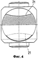
Фиг.4 представляет собой вид, половина которого является частичным разрезом по линии IV-IV на Фиг.3, а вторая половина - видом сбоку.Figure 4 is a view, half of which is a partial section along the line IV-IV in Figure 3, and the second half is a side view.
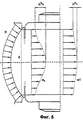
На Фиг.5 представлен вид части затвора шарового клапана по данному изобретению, показанного на Фиг.3, с иллюстрацией напряжений и деформации элементов.Figure 5 presents a view of a part of the shutter of the ball valve according to this invention, shown in Figure 3, with illustration of stresses and deformation of the elements.
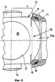
На Фиг.6 дан еще один неполный вид частично смонтированного затвора, показанного на Фиг.3.Figure 6 is another partial view of the partially mounted shutter shown in Figure 3.
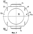
Фиг.7 представляет собой вид сбоку в уменьшенном масштабе затвора в соответствии со вторым вариантом осуществления изобретения.7 is a side view in a reduced scale of the shutter in accordance with the second embodiment of the invention.
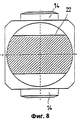
На Фиг.8 дан разрез по линии VIII-VIII на Фиг.7.On Fig given a section along the line VIII-VIII in Fig.7.
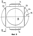
Фиг.9 представляет собой вид сбоку в уменьшенном масштабе затвора в соответствии с третьим вариантом осуществления изобретения.Fig.9 is a side view in a reduced scale of the shutter in accordance with a third embodiment of the invention.
На Фиг.10 дан разрез по линии Х-Х на Фиг.9.Figure 10 is a section along the line XX in Figure 9.
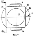
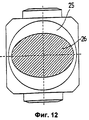
Фиг.11 представляет собой вид сбоку в уменьшенном масштабе затвора в соответствии с четвертым вариантом осуществления изобретения.11 is a side view on a reduced scale of the shutter in accordance with the fourth embodiment of the invention.
На Фиг.12 дан разрез по линии XI-XI на Фиг.11.On Fig given a section along the line XI-XI in Fig.11.
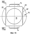
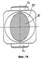
Фиг.13 представляет собой вид сбоку в уменьшенном масштабе затвора в соответствии с пятым вариантом осуществления изобретения.13 is a side view on a reduced scale of the shutter in accordance with the fifth embodiment of the invention.
На Фиг.14 дан разрез по линии XIV-XIV на Фиг.13.On Fig given a section along the line XIV-XIV in Fig.13.
ПОДРОБНОЕ ОПИСАНИЕ ЧЕРТЕЖЕЙDETAILED DESCRIPTION OF THE DRAWINGS
На Фиг.3-14 проиллюстрирован ряд примеров выполнения клапана с регулируемой деформацией шарика, различающихся конструкцией затвора.Figure 3-14 illustrates a number of examples of the execution of the valve with adjustable deformation of the ball, differing in the design of the shutter.
Как сказано выше, на Фиг.3-6 продемонстрирован первый вариант выполнения клапана с регулируемой деформацией шарика согласно изобретению, содержащего, главным образом, наружный защитный корпус 11, на противоположных сторонах которого размещены два кольцевых седла 12. Эти противолежащие кольцевые седла 12 обращены, по существу, соответственно в сторону патрубка впуска и патрубка выпуска текучей среды, которая поступает в клапан и/или отсекается с его помощью.As described above, Figs. 3-6 show a first embodiment of a ball deformable valve according to the invention, comprising mainly an outer
Кроме того, в состав клапана входит обозначенный общей позицией 13 затвор, установленный с возможностью вращения от не показанного здесь приводного вала, который может быть соединен с насадками 14, установленными перпендикулярно вышеупомянутым патрубкам.In addition, the valve includes a shutter, designated 13, mounted rotatably from a drive shaft not shown here, which can be connected to
Из чертежей видно, что использованный здесь затвор 13 имеет форму шарика, который может перемещаться между закрытым и открытым положениями шарового клапана. Если смотреть со стороны насадок 14, то можно видеть, что на противоположных сторонах боковой поверхности шарика могут быть образованы сферические участки 15, взаимодействующие с поверхностями 16 двух кольцевых седел 12. На других противолежащих участках, которые выполнены плоскими, выполнены окна 17, соединяющиеся с центральным отверстием 18 для циркуляции текучей среды.From the drawings it can be seen that the
Совершенно очевидно, что кольцевые седла 12 могут иметь, в зависимости от конкретного размещения, самую разнообразную форму, которая обеспечивала бы возможность установки не показанных здесь уплотняющих элементов.It is obvious that the
В соответствии с данным изобретением на противоположных сторонах как сверху, так и снизу между сферическими участками 15 и центральной зоной затвора выполнены канавки 19 и 20, образующие своего рода колпачки 15а и 15b. Канавки 19 и 20 заходят на некоторое изменяющееся расстояние L внутрь сферических участков в направлении, параллельном оси R вращения затвора. Они выполняются в зонах, находящихся вблизи насадок 14.According to the invention, on the opposite sides, both above and below, between the
Благодаря наличию канавок 19 и 20, образующих два колпачка 15а и 15b, обеспечивается достаточно равномерная деформация затвора клапана, в частности, по всей зоне контакта с кольцевыми седлами 12. Более четко это показано на Фиг.6.Due to the presence of
Разумеется, можно выбрать такую оптимальную конфигурацию канавок 19 и 20, при которой были бы сведены к минимуму различия в деформации затвора клапана по всей окружности.Of course, it is possible to choose such an optimal configuration of the
Фиг.5, представляющая собой половинный вид затвора 13 согласно первому варианту выполнения изобретения, иллюстрирует действие напряжений и деформации элементов, показанные в виде теоретических линий.Figure 5, which is a half view of the
Так, кривая (е0) на Фиг.5 демонстрирует характер осевой деформации теоретической окружности контакта между сферическим участком известного затвора и кольцевым седлом 12, обозначенной здесь позицией (d). На этой диаграмме максимальная разность осевых смещений, обусловленных напряжениями, обозначена символами Δh0.Thus, the curve (e 0 ) in FIG. 5 shows the nature of the axial deformation of the theoretical contact circle between the spherical portion of the known shutter and the
Кривая же (e1) иллюстрирует осевую деформацию окружности (d) в случае, когда конфигурация затвора на его участке в виде колпачка модифицирована в соответствии с данным изобретением благодаря канавкам 19 и 20.The curve (e 1 ) illustrates the axial deformation of the circle (d) in the case when the configuration of the shutter in its portion in the form of a cap is modified in accordance with this invention due to the
Можно заметить, что здесь максимальная разность осевого смещения теоретической окружности контакта (d) равна Δh1, что существенно меньше, чем Δh0.You can see that here the maximum difference in axial displacement of the theoretical contact circumference (d) is Δh 1 , which is significantly less than Δh 0 .
Таким образом, видно, каким образом можно обеспечить лучшую регулировку затвора, выполненного согласно данному изобретению.Thus, it is seen how it is possible to provide better adjustment of the shutter made according to this invention.
По существу, в соответствии с данным изобретением, конфигурация сферического участка затвора изменяется за счет повышения деформируемости в двух зонах, верхней и нижней, прилегающих к насадкам, или ступицам, 14. Такое решение в корне отличается от принятых в известных конструкциях, где наличие ступиц придает этим зонам большую жесткость по сравнению с центральными зонами.Essentially, in accordance with this invention, the configuration of the spherical section of the shutter changes due to increased deformability in two zones, the upper and lower, adjacent to the nozzles or hubs, 14. This solution is fundamentally different from that adopted in known constructions, where the presence of hubs gives these zones are more stiff than the central zones.
В примере, показанном на Фиг.3-6, канавки 19 и 20 имеют криволинейную форму основания 21.In the example shown in FIGS. 3-6, the
Однако можно использовать и другие самые разнообразные формы основания канавки либо выполнить ее по всей длине сферического участка 15.However, you can use the other most diverse forms of the base of the groove or run it along the entire length of the
Так, на Фиг.7 и 8 канавки 19 и 20 имеют основание 22 прямолинейной формы.So, in FIGS. 7 and 8, the
На Фиг.9 и 10 продемонстрирован третий вариант выполнения затвора согласно изобретению, в соответствии с которым противолежащие канавки объединены в сплошные кольцевые канавки 23. В результате, образуемые благодаря им сферические колпачки оказываются "сидящими" на круговом центральном участке меньшего диаметра 24 наподобие грибных шляпок.Figures 9 and 10 show a third embodiment of the shutter according to the invention, according to which the opposing grooves are combined into continuous
На Фиг.11 и 12 показан четвертый вариант выполнения затвора согласно изобретению, в соответствии с которым, как и в предыдущей конструкции, выполнена канавка 25 по всей длине сферического участка 15.11 and 12 show a fourth embodiment of a shutter according to the invention, according to which, as in the previous design, a
Глубина этой канавки 25 изменяется таким образом, что образуемые ею сферические колпачки "сидят" на центральном участке меньшего размера 26, имеющего форму, близкую к эллипсу, большая ось которого направлена перпендикулярно к оси вращения R затвора 13.The depth of this
Наконец, соображения, высказанные при рассмотрении Фиг.11 и 12, имеют силу и для конструкции согласно пятому варианту, изображенной на Фиг.13 и 14, которая отличается лишь тем, что такой же эллиптический центральный участок 26' повернут на 90° относительно рассмотренного выше.Finally, the considerations expressed when considering Figs. 11 and 12 are also valid for the design according to the fifth embodiment shown in Figs. 13 and 14, which differs only in that the same elliptical central portion 26 'is rotated 90 ° relative to the above .
Периферийную канавку также можно выполнить в соответствии с другим профилем так, чтобы получался центральный участок меньшего размера и с иной формой.The peripheral groove can also be made in accordance with a different profile so that a central portion of a smaller size and with a different shape is obtained.
Таким образом, благодаря предложенному шаровому клапану найдено эффективное решение технических проблем, возникающих при работе с известными затворами. Действительно, благодаря наличию канавок на сферических участках при приложении давления достигается выравнивание в этих зонах упругих деформаций при соприкосновении с соответствующими седлами.Thus, thanks to the proposed ball valve, an effective solution to the technical problems encountered when working with known valves has been found. Indeed, due to the presence of grooves in the spherical sections, when pressure is applied, alignment of elastic deformations in these zones when they contact the corresponding saddles is achieved.
Следует заметить, что показанные на Фиг.6 канавки должны быть выполнены за седлом 12 или за зоной действия давления, то есть в пределах участка, обозначенного буквой X.It should be noted that the grooves shown in FIG. 6 must be made behind the
Кроме того, как было показано выше, канавка, или зона снятия напряжений, может быть выполнена с различной конфигурацией в зависимости от размеров сферических участков, величины рабочего давления и других отдельных факторов.In addition, as shown above, the groove, or stress relief zone, can be made with a different configuration depending on the size of the spherical sections, the magnitude of the working pressure and other individual factors.
Таким образом, возможность выравнивания деформаций затвора на сферических участках позволяет улучшить работу шаровых клапанов, причем эти результаты достигаются при использовании как эластомерных или термопластичных вкладышей, так и металлических вкладышей, а также при любых давлениях - как низких, так и высоких.Thus, the possibility of equalizing the shutter deformations in spherical sections allows to improve the operation of ball valves, and these results are achieved using both elastomeric or thermoplastic liners and metal liners, as well as at any pressure - both low and high.
В результате технические решения, подобные предложенному, оказываются применимыми к шаровым клапанам любых типов.As a result, technical solutions like the one proposed turn out to be applicable to all types of ball valves.
Из изложенного выше следует, что техническое решение по данному изобретению дает возможность получить более равномерное деформирование шарика.From the above it follows that the technical solution according to this invention makes it possible to obtain a more uniform deformation of the ball.
Можно, следовательно, утверждать, что оно обеспечивает то же качество уплотнения, что и известные конструкции шаровых клапанов, но при работе с гораздо более высокими давлениями:It can therefore be argued that it provides the same seal quality as the well-known ball valve designs, but when working with much higher pressures:
![]()
![]()
Из этого следует, что для получения такого же качества герметизации можно прикладывать к седлу меньшее усилие. По сути дела, для того чтобы повторять деформации шарика, которые гораздо более сильно ограничены, седлу приходится испытывать меньшую деформацию. В результате становится возможным управлять работой клапанов или затворов, используя менее значительные моменты силы.It follows that to obtain the same sealing quality, less force can be applied to the seat. In fact, in order to repeat the ball deformations, which are much more severely limited, the saddle has to experience less deformation. As a result, it becomes possible to control the operation of the valves or closures using less significant moments of force.
Следует также заметить, что затвор с особой формой сферических участков можно выполнить либо из металла, используя литые, кованые, катаные или сварные детали, либо из любых подходящих пластмасс или композитных материалов.It should also be noted that the shutter with a special shape of spherical sections can be made either from metal using cast, forged, rolled or welded parts, or from any suitable plastics or composite materials.
Claims (5)
Applications Claiming Priority (2)
| Application Number | Priority Date | Filing Date | Title |
|---|---|---|---|
| IT1998MI002157A IT1302619B1 (en) | 1998-10-07 | 1998-10-07 | CONTROLLED DEFORMATION BALL VALVE |
| ITMI98A002157 | 1998-10-07 |
Publications (2)
| Publication Number | Publication Date |
|---|---|
| RU2000114630A RU2000114630A (en) | 2002-05-20 |
| RU2249744C2 true RU2249744C2 (en) | 2005-04-10 |
Family
ID=11380826
Family Applications (1)
| Application Number | Title | Priority Date | Filing Date |
|---|---|---|---|
| RU2000114630/06A RU2249744C2 (en) | 1998-10-07 | 1999-08-30 | Valve at adjustable deformation of ball |
Country Status (13)
| Country | Link |
|---|---|
| US (1) | US6695286B1 (en) |
| EP (1) | EP1034391B1 (en) |
| JP (1) | JP4441119B2 (en) |
| AR (1) | AR020663A1 (en) |
| AT (1) | ATE258286T1 (en) |
| BR (1) | BR9906851A (en) |
| CA (1) | CA2313207C (en) |
| DE (1) | DE69914301T2 (en) |
| IT (1) | IT1302619B1 (en) |
| RU (1) | RU2249744C2 (en) |
| SK (1) | SK286206B6 (en) |
| WO (1) | WO2000020783A1 (en) |
| ZA (1) | ZA200002706B (en) |
Cited By (1)
| Publication number | Priority date | Publication date | Assignee | Title |
|---|---|---|---|---|
| RU212771U1 (en) * | 2022-04-05 | 2022-08-08 | Федеральное Государственное Унитарное Предприятие "Всероссийский Научно-Исследовательский Институт Автоматики Им.Н.Л.Духова" (Фгуп "Внииа") | check valve |
Families Citing this family (14)
| Publication number | Priority date | Publication date | Assignee | Title |
|---|---|---|---|---|
| US20070069173A1 (en) * | 2005-09-29 | 2007-03-29 | Zachman James R | High pressure ball valve seal assembly |
| US8225871B2 (en) * | 2006-11-09 | 2012-07-24 | Baker Hughes Incorporated | Bidirectional sealing mechanically shifted ball valve for downhole use |
| US7810571B2 (en) * | 2006-11-09 | 2010-10-12 | Baker Hughes Incorporated | Downhole lubricator valve |
| US8113286B2 (en) * | 2006-11-09 | 2012-02-14 | Baker Hughes Incorporated | Downhole barrier valve |
| US7905292B2 (en) * | 2009-02-06 | 2011-03-15 | Baker Hughes Incorporated | Pressure equalization device for downhole tools |
| US8534361B2 (en) * | 2009-10-07 | 2013-09-17 | Baker Hughes Incorporated | Multi-stage pressure equalization valve assembly for subterranean valves |
| US8336628B2 (en) * | 2009-10-20 | 2012-12-25 | Baker Hughes Incorporated | Pressure equalizing a ball valve through an upper seal bypass |
| US9140153B2 (en) * | 2013-06-05 | 2015-09-22 | Ford Global Technologies, Llc | Engine system having a backflow valve and method for operation thereof |
| KR101579600B1 (en) * | 2014-05-08 | 2015-12-22 | 김충호 | Manufacturing method for metal seal valve and metal seal valve therof |
| KR101595260B1 (en) * | 2014-08-22 | 2016-02-18 | 대우조선해양 주식회사 | Seat Retainer for Ball Valve |
| KR101595264B1 (en) * | 2014-08-22 | 2016-02-18 | 대우조선해양 주식회사 | Ball Valve |
| KR101595268B1 (en) * | 2014-08-25 | 2016-02-18 | 대우조선해양 주식회사 | Oval Seat Retainer for Ball Valve |
| KR101825220B1 (en) * | 2017-08-07 | 2018-02-02 | (주)케이에스티플랜트 | Metal seat ball valve apparatus for use in a cryogenic environment and method for manufacturing thereof |
| CN107940016B (en) * | 2017-12-14 | 2023-11-10 | 台州艾迪西盛大暖通科技有限公司 | Sealing ball valve |
Family Cites Families (5)
| Publication number | Priority date | Publication date | Assignee | Title |
|---|---|---|---|---|
| US3130952A (en) | 1964-04-28 | Sealing means for high pressure valves | ||
| GB457279A (en) * | 1934-05-25 | 1936-11-24 | Jean Bugatti | Improvements in or relating to valves |
| NL128847C (en) * | 1964-03-13 | 1969-12-15 | ||
| US3348805A (en) * | 1964-09-08 | 1967-10-24 | Worcester Valve Co Inc | Ball valve |
| GB2156496B (en) * | 1981-04-15 | 1986-02-05 | Dereve | Fluid pressure governor |
-
1998
- 1998-10-07 IT IT1998MI002157A patent/IT1302619B1/en active IP Right Grant
-
1999
- 1999-08-30 CA CA002313207A patent/CA2313207C/en not_active Expired - Fee Related
- 1999-08-30 BR BR9906851-6A patent/BR9906851A/en not_active IP Right Cessation
- 1999-08-30 EP EP99939562A patent/EP1034391B1/en not_active Expired - Lifetime
- 1999-08-30 DE DE69914301T patent/DE69914301T2/en not_active Expired - Lifetime
- 1999-08-30 US US09/555,910 patent/US6695286B1/en not_active Expired - Fee Related
- 1999-08-30 AT AT99939562T patent/ATE258286T1/en not_active IP Right Cessation
- 1999-08-30 RU RU2000114630/06A patent/RU2249744C2/en not_active IP Right Cessation
- 1999-08-30 JP JP2000574858A patent/JP4441119B2/en not_active Expired - Fee Related
- 1999-08-30 SK SK833-2000A patent/SK286206B6/en not_active IP Right Cessation
- 1999-08-30 WO PCT/IB1999/001490 patent/WO2000020783A1/en active IP Right Grant
- 1999-09-27 AR ARP990104868A patent/AR020663A1/en active IP Right Grant
-
2000
- 2000-05-30 ZA ZA200002706A patent/ZA200002706B/en unknown
Cited By (1)
| Publication number | Priority date | Publication date | Assignee | Title |
|---|---|---|---|---|
| RU212771U1 (en) * | 2022-04-05 | 2022-08-08 | Федеральное Государственное Унитарное Предприятие "Всероссийский Научно-Исследовательский Институт Автоматики Им.Н.Л.Духова" (Фгуп "Внииа") | check valve |
Also Published As
| Publication number | Publication date |
|---|---|
| CA2313207A1 (en) | 2000-04-13 |
| BR9906851A (en) | 2000-10-10 |
| EP1034391B1 (en) | 2004-01-21 |
| ZA200002706B (en) | 2002-02-28 |
| SK286206B6 (en) | 2008-05-06 |
| IT1302619B1 (en) | 2000-09-29 |
| DE69914301T2 (en) | 2004-11-25 |
| US6695286B1 (en) | 2004-02-24 |
| ATE258286T1 (en) | 2004-02-15 |
| JP4441119B2 (en) | 2010-03-31 |
| JP2002526734A (en) | 2002-08-20 |
| SK8332000A3 (en) | 2001-07-10 |
| AR020663A1 (en) | 2002-05-22 |
| DE69914301D1 (en) | 2004-02-26 |
| WO2000020783A1 (en) | 2000-04-13 |
| ITMI982157A1 (en) | 2000-04-07 |
| CA2313207C (en) | 2007-03-27 |
| EP1034391A1 (en) | 2000-09-13 |
Similar Documents
| Publication | Publication Date | Title |
|---|---|---|
| RU2249744C2 (en) | Valve at adjustable deformation of ball | |
| CN104989839B (en) | Ball valve | |
| US9175778B2 (en) | Sealing microsawtooth ring joint of two opposing surfaces | |
| EP3058256B1 (en) | Floating ball valve seal | |
| WO2016115076A1 (en) | Extreme service plug valve | |
| EP1769177A1 (en) | Fluid valve control members having contoured sealing surfaces | |
| TWI794389B (en) | butterfly valve | |
| JPH07269719A (en) | Valve with seal ring with periphery-welded laminate | |
| AU6938198A (en) | Ball valve with improved valve seat and bonnet assembly | |
| US11143312B2 (en) | Eccentric rotary valve | |
| US20220163128A1 (en) | Butterfly valve seat and valve seat cavity | |
| AU698571B2 (en) | Hemispherical ball valve | |
| US3874631A (en) | Adjustable, corrosion-resistant, butterfly valve | |
| AU776740B2 (en) | Valve with ball of controlled deformation | |
| CN210014046U (en) | Valve core and coal slurry backflow control valve | |
| RU2434170C1 (en) | Valve head | |
| RU2279006C2 (en) | Rotary gate valve | |
| EP1540213B1 (en) | Ball valve | |
| RU178568U1 (en) | VALVE LATTER SHUTTER | |
| JPH0138376Y2 (en) | ||
| KR200298637Y1 (en) | Ball valve sealing device | |
| RU2273782C1 (en) | Ball cock | |
| CN1179819A (en) | Angle entry rotary valve | |
| JPH06213338A (en) | Top entry type ball valve and method for its assembly | |
| KR20040000897A (en) | Butterfly valve |
Legal Events
| Date | Code | Title | Description |
|---|---|---|---|
| MM4A | The patent is invalid due to non-payment of fees |
Effective date: 20140831 |