RU2243847C2 - Blow - through plug - Google Patents
Blow - through plug Download PDFInfo
- Publication number
- RU2243847C2 RU2243847C2 RU2002105480/02A RU2002105480A RU2243847C2 RU 2243847 C2 RU2243847 C2 RU 2243847C2 RU 2002105480/02 A RU2002105480/02 A RU 2002105480/02A RU 2002105480 A RU2002105480 A RU 2002105480A RU 2243847 C2 RU2243847 C2 RU 2243847C2
- Authority
- RU
- Russia
- Prior art keywords
- gap
- housing
- purge plug
- melt
- bottom element
- Prior art date
Links
Images

Classifications
-
- B—PERFORMING OPERATIONS; TRANSPORTING
- B22—CASTING; POWDER METALLURGY
- B22D—CASTING OF METALS; CASTING OF OTHER SUBSTANCES BY THE SAME PROCESSES OR DEVICES
- B22D1/00—Treatment of fused masses in the ladle or the supply runners before casting
-
- B—PERFORMING OPERATIONS; TRANSPORTING
- B22—CASTING; POWDER METALLURGY
- B22D—CASTING OF METALS; CASTING OF OTHER SUBSTANCES BY THE SAME PROCESSES OR DEVICES
- B22D1/00—Treatment of fused masses in the ladle or the supply runners before casting
- B22D1/002—Treatment with gases
- B22D1/005—Injection assemblies therefor
-
- C—CHEMISTRY; METALLURGY
- C21—METALLURGY OF IRON
- C21C—PROCESSING OF PIG-IRON, e.g. REFINING, MANUFACTURE OF WROUGHT-IRON OR STEEL; TREATMENT IN MOLTEN STATE OF FERROUS ALLOYS
- C21C5/00—Manufacture of carbon-steel, e.g. plain mild steel, medium carbon steel or cast steel or stainless steel
- C21C5/28—Manufacture of steel in the converter
- C21C5/42—Constructional features of converters
- C21C5/46—Details or accessories
- C21C5/48—Bottoms or tuyéres of converters
Landscapes
- Engineering & Computer Science (AREA)
- Chemical & Material Sciences (AREA)
- Mechanical Engineering (AREA)
- Materials Engineering (AREA)
- Metallurgy (AREA)
- Organic Chemistry (AREA)
- Manufacturing & Machinery (AREA)
- Treatment Of Steel In Its Molten State (AREA)
- Carbon Steel Or Casting Steel Manufacturing (AREA)
- Casting Support Devices, Ladles, And Melt Control Thereby (AREA)
- Furnace Details (AREA)
- Manufacture And Refinement Of Metals (AREA)
- Taps Or Cocks (AREA)
- Lift Valve (AREA)
- Valve Housings (AREA)
Abstract
Description
Изобретение относится к продувочной пробке, устанавливаемой с возможностью замены в дно литейного ковша для продувки газа через расплав в литейном ковше, причем продувочная пробка содержит керамический корпус, имеющий по меньшей мере один сквозной зазор, проходящий между торцевыми поверхностями корпуса, и оболочку, которая охватывает корпус, при этом газ подают к наружной торцевой поверхности корпуса для его прохождения при заданном давлении через зазор к внутренней торцевой поверхности корпуса и в расплав.The invention relates to a purge plug installed with the possibility of replacing the bottom of the casting ladle to purge gas through the melt in the casting ladle, the purge plug comprising a ceramic body having at least one through gap extending between the end surfaces of the body and a shell that covers the body , while the gas is supplied to the outer end surface of the housing for its passage at a given pressure through the gap to the inner end surface of the housing and to the melt.
Продувочные пробки обычно используют для перемешивания расплава в литейном ковше и, когда это необходимо, также для модифицирования расплава и для пропускания газа под высоким давлением, например, составляющим 6-10 бар, в литейный ковш. Известная продувочная пробка состоит из газопроницаемого керамического конуса, имеющего конфигурацию усеченного конуса весом около 10 кг, который заключен в оболочку из листового металла. Продувочную пробку обычно поставляют в составе так называемых комплектов, то есть конуса, установленного в полый блок, который весит около 50 кг.Purge plugs are typically used to mix the melt in the casting ladle and, when necessary, also to modify the melt and to pass gas under high pressure, for example, 6-10 bar, into the casting ladle. The known purge plug consists of a gas-permeable ceramic cone having a truncated cone configuration weighing about 10 kg, which is enclosed in a sheet metal sheath. The purge plug is usually supplied as part of the so-called kits, that is, a cone mounted in a hollow block that weighs about 50 kg.
Продувочная пробка играет ключевую роль при производстве чистой стали, и ее используют практически на всех сталеплавильных заводах мира. Одну или более продувочных пробок устанавливают с возможностью замены в дно устройства, которое можно встретить на всех сталеплавильных заводах и которое называется литейным ковшом, то есть контейнера, облицованного огнеупорным материалом и предназначенного для приема расплавленной стали. В литейном ковше осуществляются различные высокотемпературные химические процессы, в ходе которых продувочная пробка играет важную роль. Обычно через продувочную пробку продувают такой газ, как аргон. Продувочная пробка в ходе процесса сильно изнашивается в своей верхней части, которая обращена к расплаву, и ее необходимо регулярно заменять новой продувочной пробкой, когда высота пробки уменьшается до минимального допустимого уровня.Blow-off plug plays a key role in the production of pure steel, and it is used in almost all steel plants in the world. One or more purge plugs is installed with the possibility of replacement at the bottom of the device, which can be found in all steel mills and which is called the casting ladle, that is, a container lined with refractory material and designed to receive molten steel. Various high-temperature chemical processes are carried out in the casting ladle, during which the purge plug plays an important role. Typically, a gas such as argon is purged through a purge plug. The purge plug during the process wears out strongly in its upper part, which faces the melt, and must be regularly replaced with a new purge plug when the height of the plug is reduced to the minimum acceptable level.
Первые продувочные пробки были пористыми, то есть они были газопроницаемыми, но не позволяли стали протекать через них. Недостатком таких продувочных пробок было то, что для получения достаточного потока газа требовалось использование газа под высоким давлением и вследствие их пористости возникал значительный износ.The first purge plugs were porous, that is, they were gas permeable, but did not allow them to flow through them. The disadvantage of such purge plugs was that in order to obtain a sufficient gas flow, the use of gas under high pressure was required and considerable wear occurred due to their porosity.
Следующим этапом усовершенствования продувочных пробок было использование так называемой направленной пористости, то есть посредством отливки формировалось множество каналов диаметром около 0,5 мм, и газ продували через эти каналы. Преимущество этой продувочной пробки заключается в том, что через нее легко проходит поток газа и то, что пробка получается компактной, что означает меньший износ. Недостатком является больший риск просачивания стали в каналы, что приводит к закупориванию продувочной пробки.The next step in improving purge plugs was the use of so-called directional porosity, i.e., many channels with a diameter of about 0.5 mm were formed by casting, and gas was purged through these channels. The advantage of this purge plug is that a gas stream easily passes through it and that the plug is compact, which means less wear. The disadvantage is a greater risk of steel leaking into the channels, which leads to clogging of the purge plug.
Третьим этапом в усовершенствовании продувочных пробок было формирование в продувочной пробке при отливке не каналов, а пазов или выемок, имеющих ширину около 0,2 мм и длину около 20 мм. Благодаря этому можно увеличить расход газа без просачивания стали в пазы. Однако риск просачивания стали всегда оставался, поскольку в продувочной пробке все же были открытые отверстия.The third step in improving the purge plugs was the formation in the purge plug when casting not channels, but grooves or recesses having a width of about 0.2 mm and a length of about 20 mm. Due to this, it is possible to increase gas consumption without leaking steel into the grooves. However, the risk of steel seepage always remained, since there were still open holes in the purge plug.
Продувочная пробка должна отвечать трем требованиям: долгий срок службы, удовлетворительная проницаемость для газа и исключение просачивания стали в отверстия продувочной пробки.The purge plug must meet three requirements: a long service life, satisfactory gas permeability, and the exclusion of steel from seeping into the vent plug holes.
Удовлетворительный срок службы обеспечивается за счет выполнения продувочной пробки из высококачественного, компактного огнеупорного материала.Satisfactory service life is ensured by blowing plugs made of high quality, compact refractory material.
Высокая степень проницаемости для газа достигается применением отверстий, имеющих достаточную площадь поперечного сечения.A high degree of gas permeability is achieved by using openings having a sufficient cross-sectional area.
Минимальное просачивание достигается применением достаточно узких отверстий.Minimum leakage is achieved by using sufficiently narrow holes.
Эти три требования противоречат друг другу, и продувочная пробка является компромиссом между этими тремя характеристиками.These three requirements contradict each other, and the purge plug is a compromise between these three characteristics.
В патенте ФРГ DE 19610578 описывается продувочная пробка, которая содержит наружный корпус, имеющий выемку в форме усеченного конуса в его верхней части, цилиндрическую увеличенную выемку в промежуточной части и цилиндрический канал в его нижней части. Выемки сообщаются друг с другом, позволяя газу под определенным давлением протекать от одной торцевой поверхности к другой. В выемках в указанном выше порядке с возможностью перемещения как единый узел расположены усеченный конус, поршень и трубчатый шток поршня, снабженный отверстиями. Конус предварительно поджат в направлении закрытого положения наружной нажимной пружиной, которая воздействует на свободный конец штока поршня, выступающий из продувочной пробки. Когда газ под достаточным давлением (для противодействия силе пружины и металлургическому давлению) подают по трубопроводу и через шток поршня в увеличенную выемку, поршень поднимает конус и открывается зазор между выемкой в форме конуса и конусом. В таком случае газ может протекать вокруг поршня и через зазор в расплав.In the German patent DE 19610578, a purge plug is described which comprises an outer casing having a recess in the form of a truncated cone in its upper part, a cylindrical enlarged recess in the intermediate part and a cylindrical channel in its lower part. The recesses communicate with each other, allowing gas to flow under a certain pressure from one end surface to another. A truncated cone, a piston and a tubular piston rod provided with holes are located in the recesses in the above order with the possibility of moving as a single unit. The cone is pre-pressed in the closed position by an external pressure spring, which acts on the free end of the piston rod protruding from the purge plug. When gas under sufficient pressure (to counteract the force of the spring and metallurgical pressure) is supplied through the pipeline and through the piston rod to the enlarged recess, the piston raises the cone and a gap opens between the recess in the form of a cone and the cone. In this case, gas can flow around the piston and through the gap into the melt.
Недостатками этой конструкции являются следующие.The disadvantages of this design are as follows.
- Конструкция очень сложна в изготовлении, поскольку продувочные пробки обычно отливают из огнеупорного материала. Трудно технически выполнить промежуточную увеличенную выемку (16) посредством литья, поскольку очень трудно извлечь шаблон, используемый для литья.- The design is very difficult to manufacture, since purge plugs are usually cast from refractory material. It is technically difficult to make the intermediate enlarged recess (16) by casting, since it is very difficult to remove the mold used for casting.
- Конструкция имеет сложные выступающие детали (подвеска пружины под продувочной пробкой), которые неудобны в условиях сталелитейного производства, поскольку они могут легко повреждаться под воздействием ударов или грубого обращения.- The design has complex protruding parts (spring suspension under the purge plug), which are inconvenient in steelmaking, as they can easily be damaged by impact or rough handling.
- Подвеска пружины дорога в изготовлении.- Suspension spring road to manufacture.
- Продувочная пробка постепенно изнашивается. Когда она износится до увеличенной выемки (16), может произойти прорыв сквозь пробку и сталь может вытекать из дна литейного ковша с катастрофическими результатами. Таким образом, очень важно, чтобы пробка не изнашивалась до этого уровня. Для определения изношенности продувочной пробки требуется дополнительное оборудование.- The purge plug gradually wears out. When it wears out to an enlarged recess (16), a break through the cork may occur and steel may leak from the bottom of the casting ladle with catastrophic results. Therefore, it is very important that the cork does not wear out to this level. Additional equipment is required to determine the deterioration of the purge plug.
Кроме того, известна продувочная пробка, снабженная подвижным элементом и неподвижным элементом и кольцевым зазором, через который протекает газ (патент США US-A 4470582).In addition, a purge plug is known, provided with a movable element and a fixed element and an annular gap through which gas flows (US Pat. No. 4,470,582).
Эта конструкция отличается от указанной выше конструкции по патенту ФРГ главным образом тем, что пружина для прижима заменена рычажным механизмом, который предварительно нагружен гидравлическим цилиндром.This design differs from the above design according to the Federal Republic of Germany patent mainly in that the spring for the clamp is replaced by a lever mechanism that is preloaded with a hydraulic cylinder.
Недостатками этой конструкции являются следующие.The disadvantages of this design are as follows.
- Из-за сложной конфигурации она очень дорога в изготовлении.- Due to the complex configuration, it is very expensive to manufacture.
- Расход газа регулируется внешним клапаном, который открывает и закрывает кольцевой зазор посредством направления подвижного элемента вверх и вниз соответственно. Недостаток состоит в том, что требуется внешнее управляющее устройство, которое занимает много места и является неудобным в условиях сталелитейного производства. Оно может быть легко повреждено воздействием внешних сил.- The gas flow is regulated by an external valve, which opens and closes the annular gap by moving the movable element up and down, respectively. The disadvantage is that an external control device is required, which takes up a lot of space and is inconvenient in the conditions of steel production. It can be easily damaged by external forces.
Продувочная пробка по патенту США так же, как и по патенту ФРГ, изнашивается с теми же недостатками, которые отмечены выше.The purge plug according to the US patent as well as according to the patent of Germany, wears out with the same drawbacks as noted above.
Цель настоящего изобретения заключается в создании продувочной пробки, имеющей зазор, ширина которого является функцией давления используемого газа, и которая проста и недорога при изготовлении.An object of the present invention is to provide a purge plug having a gap, the width of which is a function of the pressure of the gas used, and which is simple and inexpensive to manufacture.
Другой целью изобретения является создание продувочной пробки с регулируемым зазором, которая не требует сложных механизмов и не имеет каких-либо выступающих элементов.Another objective of the invention is to provide a purge plug with an adjustable gap that does not require complex mechanisms and does not have any protruding elements.
Еще одной целью является создание надежной продувочной пробки, которая может изнашиваться более или менее полностью до того, как происходит прорыв.Another goal is to create a reliable purge plug that can wear out more or less completely before a breakthrough occurs.
Согласно изобретению эти цели достигаются созданием продувочной пробки вышеуказанного типа, которая отличается тем, что керамический корпус содержит наружную часть преимущественно в форме гильзы и внутреннюю часть в форме усеченного конуса, между которыми образуется зазор, причем внутренняя часть корпуса имеет возможность перемещения относительно наружной части корпуса и предварительно нагружена упругим средством в направлении расплава для закрывания зазора, а труба для подачи газа соединена с пространством под наружной торцевой поверхностью для открывания зазора.According to the invention, these goals are achieved by creating a purge plug of the aforementioned type, which is characterized in that the ceramic body comprises an outer part predominantly in the form of a sleeve and an inner part in the form of a truncated cone, between which a gap is formed, and the inner part of the housing can move relative to the outer part of the housing preloaded with elastic means in the melt direction to close the gap, and the gas supply pipe is connected to the space under the outer end face a surface for opening the gap.
Другие преимущества изобретения очевидны из признаков, включенных в зависимые пункты формулы изобретения.Other advantages of the invention are apparent from the features included in the dependent claims.
Ниже изобретение поясняется более подробно на примере его выполнения, показанном на прилагаемых чертежах на которых:Below the invention is explained in more detail on the example of its implementation, shown in the accompanying drawings in which:
на фиг.1 изображен схематический вид в вертикальном разрезе нижней части литейного ковша с продувочными пробками,figure 1 shows a schematic view in vertical section of the lower part of the casting bucket with purge plugs,
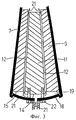
фиг.2 - продувочная пробка, согласно изобретению, в разрезе с закрытым зазором для потока газа,figure 2 - purge plug, according to the invention, in section with a closed gap for gas flow,
фиг.3 - продувочная пробка, аналогичная показанной на фиг.2, с открытым зазором для потока газа,figure 3 - purge plug, similar to that shown in figure 2, with an open gap for gas flow,
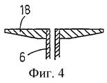
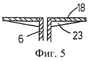
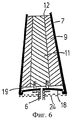
фиг.4, фиг.5 и фиг.6 - различные варианты выполнения нижней пластины продувочной пробки,4, 5 and 6 are various embodiments of the bottom plate of the purge plug,
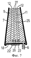
фиг.7 - альтернативный вариант выполнения продувочной пробки, согласно изобретению.7 is an alternative embodiment of a purge plug according to the invention.
На фиг.1 схематически показана нижняя часть литейного ковша 1 для расплава 2, обычно расплава металла, например стали. Ряд сменных продувочных пробок 4 известным способом с возможностью их отсоединения установлен в дно 3 литейного ковша при помощи известных крепежных средств, обозначенных позицией 5. С каждой продувочной пробкой 4 соединена труба 6 для подачи газа. Все это относится к известному уровню техники и, таким образом, не требует дополнительных разъяснений.Figure 1 schematically shows the lower part of the casting ladle 1 for melt 2, usually a molten metal, such as steel. A number of interchangeable purge plugs 4 in a known manner with the possibility of detaching them are installed in the bottom 3 of the casting ladle using known fastening means, indicated by 5. The
На фиг.2 и 3 показаны конструкция и работа продувочной пробки согласно изобретению. Продувочная пробка 4 содержит оболочку 7. Поскольку продувочная пробка 4 должна использоваться с расплавом 2 из стали, оболочку предпочтительно выполняют тоже из стали. Оболочка выполнена в форме усеченного конуса, суженный конец которого входит в контакт с расплавом (см. фиг.1), но она также может быть перевернутой или цилиндрической (не показано). В оболочку 7 заключен керамический корпус 8 и предпочтительно прикреплен к ней по всей его длине. Предпочтительно корпус 8 отлит непосредственно внутри оболочки.Figure 2 and 3 shows the design and operation of the purge plugs according to the invention. The purge plug 4 comprises a
Корпус 8 в свою очередь разделен на наружную концентрическую, имеющую преимущественно форму гильзы часть 9 с внутренней выемкой в форме усеченного конуса, и внутреннюю часть 11 в форме усеченного конуса, которая полностью занимает выемку. Внутренняя часть 11 корпуса подвижна, то есть может перемещаться в продольном направлении относительно наружной части 9 корпуса, при этом между ними образуется зазор 12. При изготовлении частей 9 и 11 корпуса внутренняя часть 11 может легко формироваться и подгоняться к наружной части 9 посредством помещения предварительно сформированной в конфигурации усеченного конуса формы из пластмассовой пленки или пластмассового листа концентрически в оболочку 7 при отливке и затем извлечения ее, когда огнеупорный материал (керамический состав) затвердеет. Кроме того, при отливке в большей торцевой поверхности 14 внутренней части 11 корпуса могут формироваться резьбовые глухие отверстия 13 или могут заливаться резьбовые вставки.The
Предпочтительно, но не обязательно, большая торцевая поверхность 15 наружной части 9 корпуса находится на одном уровне с указанной выше торцевой поверхностью 14. Это также относится и к меньшим торцевым поверхностям 16 и 17 соответственно частей 9 и 11 корпуса.Preferably, but not necessarily, the
Внутренняя часть 11 корпуса может перемещаться вниз относительно неподвижной наружной части 9 корпуса (см. фиг.2) и предварительно поджимается вверх для закрывания зазора 12 упругим или эластичным средством, которое воздействует на торцевую поверхность 14.The
В предпочтительном варианте выполнения изобретения к оболочке 7 герметично прикреплена упругая донная пластина 18 на некотором расстоянии от наружной торцевой поверхности корпуса 8, в данном случае - торцевых поверхностей 14 и 15, и между ними образована полость или камера 19, в которой может повышаться давление. Это расстояние может быть небольшим и даже отсутствовать в ограниченных участках торцевых поверхностей 14 и 15 с единственным условием, что камера 19 формируется при подаче сжатой текучей среды (продувочного газа). Труба 6 для подачи газа соединяется с донной пластиной 18 и сообщается с камерой 19 для повышения в ней давления продувочным газом 21. Внутренняя часть 11 корпуса неподвижно прикреплена к донной пластине 18, например, при помощи болтов 22 или какого-либо другого крепежного средства. Зазор 12 выбирается при поджиме внутренней части 11 корпуса вверх, как показано на фиг.2, в положение примыкания к внутренней периферийной поверхности наружной части 9 корпуса благодаря предварительному нагружению донной пластины 18 и/или давлению продувочного газа.In a preferred embodiment of the invention, an
Когда необходимо продувать газ через расплав в литейном ковше, газ подают под высоким давлением в полость 19. Поскольку нижняя поверхность или торцевая поверхность 15 наружной части 9 корпуса больше нижней поверхности или торцевой поверхности 14 внутренней части 11 корпуса, донная пластина 18 изгибается наружу (см. фиг.3) и оттягивает внутреннюю часть 11 корпуса, посредством чего открывается кольцевой зазор 12, и газ может протекать в расплав. Чем большее давление прилагают, тем больший образуется зазор. Когда поток газа прекращается или давление газа понижается, донная пластина 18 за счет упругости возвращается обратно и толкает внутреннюю часть 11 корпуса назад и полностью закрывает зазор. Это предотвращает просачивание расплава в зазор 12. Конструкция этой новой продувочной пробки показывает, что можно получить почти неограниченный расход газа без какого-либо просачивания стали в зазор продувочной пробки. Это достигается тем, что размер зазора изменяется с изменением прилагаемого давления.When it is necessary to blow gas through the melt in the casting ladle, gas is supplied under high pressure into the
На фиг.2 и 3 показана донная пластина 18, имеющая постоянную толщину. Однако, конечно, можно регулировать влияние давления газа на ширину зазора посредством использования донных пластин 18 с определенными характеристиками упругости. Кроме использования с этой целью донных пластин различной толщины можно получать необходимые характеристики упругости посредством придания донной пластине неравномерной толщины, то есть когда ее толщина изменяется от ее окружности к ее центру. Пример этого показан на фиг.4. Как показано на фиг.5, можно также получить требуемые характеристики упругости посредством снабжения донной пластины с равномерной толщиной фланцами или ребрами 23 жесткости, которые расположены перпендикулярно донной пластине, предпочтительно ориентированы в радиальном направлении на донной пластине и имеют непостоянную высоту или толщину. Естественно, указанные выше признаки могут также комбинироваться для достижения необходимого действия, то есть получения необходимой ширины зазора 12 при разном удельном давлении газа.2 and 3, a
Другим способом получения необходимых характеристик упругости донной пластины, который также совместим с указанными выше, является выполнение изогнутой донной пластины 18, например внутрь, как показано на фиг.6. Для этой цели также можно формировать волнистую донную пластину (не показана).Another way to obtain the necessary characteristics of the elasticity of the bottom plate, which is also compatible with the above, is the implementation of a
Для ограничения изгибания донной пластины, например, при очень высоком давлении газа или когда зазор не должен превышать определенного значения, например 0,5 мм, можно снабжать продувочную пробку средством для ограничения изгибания, например, одним или более балочных элементов 24, обозначенных прерывистыми линиями на фиг.6. Каждый балочный элемент 24 неподвижно прикреплен к оболочке 7 (см. фиг.6) и/или прикреплен к наружной части 9 корпуса (не показано). Указанное выше средство, конечно, может быть также толстой, по существу жесткой пластиной (сравни с донной пластиной известной продувочной пробки). При необходимости, между наружной частью оболочки и концами средства для ограничения изгибания могут использоваться соединительные элементы (не показаны). Когда используется описанное выше средство для ограничения изгибания, в некоторых случаях между средством 24 и донной пластиной 18 можно расположить еще одно упругое средство (на чертеже не показано).To limit the bending of the bottom plate, for example, at very high gas pressure or when the gap should not exceed a certain value, for example 0.5 mm, a purge plug may be provided with means for restricting bending, for example, one or more beam elements 24, indicated by broken lines on Fig.6. Each beam element 24 is fixedly attached to the shell 7 (see Fig.6) and / or attached to the
Окружная поверхность внутренней части 11 корпуса и внутренняя окружная поверхность наружной части 9 корпуса определяют, как отмечалось выше, конфигурацию зазора 12. Обычно бывает предпочтительно, чтобы профиль сечения зазора, который является конфигурацией зазора в плоскости, перпендикулярной продольной оси продувочной пробки (плоскости, которая параллельна донной пластине), был круглым или овальным. Однако профиль сечения зазора полностью произволен и может быть треугольным, квадратным, или многоугольным, или в форме звезды, поскольку две части 9 и 11 корпуса могут отливаться одновременно с размещением между ними разделяющего элемента из пластмассовой пленки или пластмассового листа с определенным профилем поперечного сечения, который после отверждения состава легко извлекается.The circumference of the
Для получения особых характеристик потока газа, например для быстрых изменений расхода газа через продувочную пробку, можно, кроме того, формировать внутреннюю часть 11 корпуса с выемкой в форме усеченного конуса, в которой с возможностью перемещения располагается соответственно сформированная в конфигурации усеченного конуса самая внутренняя часть 25 корпуса (см. фиг.7). Эта самая внутренняя часть 25 корпуса работает так же, как описано в связи с внутренней частью 11 корпуса, поскольку она также жестко прикреплена к донной пластине 18, например, болтом 26. Характеристики упругости донной пластины соответственно регулируют посредством модификаций, описанных выше в связи с фиг.4 и 5. Зазору 27 между самой внутренней частью 25 и внутренней частью 11 корпуса может придаваться произвольная конфигурация в соответствии с описанным выше и предпочтительно зазор 27 формируют так же, как зазор 12, то есть при помощи еще одного формовочного элемента, располагаемого концентрически относительно описанного выше формовочного элемента, располагаемого в оболочке 7.To obtain special characteristics of the gas flow, for example, for rapid changes in the gas flow through the purge plug, it is also possible to form the
Следует отметить, что каждая подвижная часть 11, 25 корпуса сужается вверх, то есть от наружной торцевой поверхности 14, 15 к внутренней торцевой поверхности 16, 17, примыкающей к расплаву в показанных вариантах выполнения продувочной пробки, соответствующей изобретению.It should be noted that each
Благодаря выполнению продувочной пробки в соответствии с изобретением, получены следующие характеристики.By performing a purge plug in accordance with the invention, the following characteristics are obtained.
- Она является простой в изготовлении (такой же недорогой, как продувочные пробки, имеющиеся на рынке в настоящее время).“It is easy to manufacture (as inexpensive as the purge plugs currently on the market).”
- Полностью исключено просачивание.- Completely eliminated leakage.
- Соотношение давление/расход газа может приспосабливаться к требованиям соответствующих пользователей.- The pressure / gas ratio can be adapted to the requirements of the respective users.
- Может быть получен неограниченный расход газа.- Unlimited gas flow can be obtained.
Изобретение не ограничено описанными выше или показанными на чертежах вариантами, и в них могут вноситься изменения в пределах объема прилагаемой формулы изобретения.The invention is not limited to the options described above or shown in the drawings, and they may be modified within the scope of the attached claims.
Claims (10)
Applications Claiming Priority (2)
| Application Number | Priority Date | Filing Date | Title |
|---|---|---|---|
| SE9902830A SE514748C2 (en) | 1999-08-03 | 1999-08-03 | A purge plug |
| SE9902830-0 | 1999-08-03 |
Publications (2)
| Publication Number | Publication Date |
|---|---|
| RU2002105480A RU2002105480A (en) | 2003-09-27 |
| RU2243847C2 true RU2243847C2 (en) | 2005-01-10 |
Family
ID=20416610
Family Applications (1)
| Application Number | Title | Priority Date | Filing Date |
|---|---|---|---|
| RU2002105480/02A RU2243847C2 (en) | 1999-08-03 | 2000-07-20 | Blow - through plug |
Country Status (12)
| Country | Link |
|---|---|
| US (1) | US6669896B1 (en) |
| EP (1) | EP1214162B1 (en) |
| JP (1) | JP4884625B2 (en) |
| KR (1) | KR100661145B1 (en) |
| CN (1) | CN1123410C (en) |
| AT (1) | ATE283131T1 (en) |
| AU (1) | AU6331100A (en) |
| DE (1) | DE60016254T2 (en) |
| ES (1) | ES2233414T3 (en) |
| RU (1) | RU2243847C2 (en) |
| SE (1) | SE514748C2 (en) |
| WO (1) | WO2001008834A1 (en) |
Families Citing this family (7)
| Publication number | Priority date | Publication date | Assignee | Title |
|---|---|---|---|---|
| US7781464B2 (en) * | 2003-01-17 | 2010-08-24 | Bexel Pharmaceuticals, Inc. | Heterocyclic diphenyl ethers |
| US7087576B2 (en) * | 2003-10-07 | 2006-08-08 | Bexel Pharmaceuticals, Inc. | Dipeptide phenyl ethers |
| DE102004022129A1 (en) * | 2004-05-05 | 2005-12-01 | Stefan Munding | gas purge |
| CN203265622U (en) | 2011-11-03 | 2013-11-06 | 维苏维尤斯·克鲁斯布公司 | Apparatus blowing air into metallurgy container and same |
| EP2942406B1 (en) * | 2014-05-05 | 2016-04-13 | Refractory Intellectual Property GmbH & Co. KG | Fire resistant ceramic gas flushing element |
| CA2982968C (en) * | 2017-10-19 | 2020-09-22 | Refractory Intellectual Property Gmbh & Co. Kg | Refractory ceramic gas purging element |
| JP7323803B2 (en) * | 2019-11-28 | 2023-08-09 | 日本製鉄株式会社 | Ladle refining method for molten steel |
Family Cites Families (12)
| Publication number | Priority date | Publication date | Assignee | Title |
|---|---|---|---|---|
| CH595130A5 (en) * | 1975-04-24 | 1978-01-31 | Alusuisse | |
| JPS5845357U (en) * | 1981-09-21 | 1983-03-26 | 播磨耐火煉瓦株式会社 | Gas blowing device into molten metal |
| US4470582A (en) * | 1982-02-15 | 1984-09-11 | Zirconal Processes Limited | Introduction of substances into molten metal |
| ZA83976B (en) * | 1982-02-15 | 1983-11-30 | Zirconal Processes Ltd | Improvements in the introduction of substances into molten metal |
| JPS60110810A (en) * | 1983-11-21 | 1985-06-17 | Kawasaki Heavy Ind Ltd | Tuyere for bottom blowing |
| DE3907887A1 (en) | 1988-03-23 | 1989-10-26 | Radex Heraklith | Bubble brick |
| JPH08143942A (en) * | 1994-11-18 | 1996-06-04 | Toshiba Ceramics Co Ltd | Plug for gas blowing and its manufacture |
| JPH08199223A (en) * | 1995-01-20 | 1996-08-06 | Nippon Steel Corp | Gas blowing tuyere |
| US5478053A (en) * | 1995-04-10 | 1995-12-26 | North American Refractories Co. Inc. | Refractory gas purging device |
| DE19610578C1 (en) * | 1996-03-18 | 1997-04-24 | Veitsch Radex Ag | Ceramic gas flushing device for metallurgical vessels |
| SE515794C2 (en) * | 2000-05-02 | 2001-10-08 | Sahlin Gjutteknik Ab | A purge plug |
| SE0001592L (en) * | 2000-05-02 | 2001-10-08 | Sahlin Gjutteknik Ab | A purge plug |
-
1999
- 1999-08-03 SE SE9902830A patent/SE514748C2/en not_active IP Right Cessation
-
2000
- 2000-07-20 RU RU2002105480/02A patent/RU2243847C2/en not_active IP Right Cessation
- 2000-07-20 CN CN00810993A patent/CN1123410C/en not_active Expired - Fee Related
- 2000-07-20 AU AU63311/00A patent/AU6331100A/en not_active Abandoned
- 2000-07-20 DE DE60016254T patent/DE60016254T2/en not_active Expired - Lifetime
- 2000-07-20 US US10/048,247 patent/US6669896B1/en not_active Expired - Fee Related
- 2000-07-20 WO PCT/SE2000/001508 patent/WO2001008834A1/en active IP Right Grant
- 2000-07-20 KR KR1020027001357A patent/KR100661145B1/en not_active IP Right Cessation
- 2000-07-20 JP JP2001513543A patent/JP4884625B2/en not_active Expired - Fee Related
- 2000-07-20 EP EP00950175A patent/EP1214162B1/en not_active Expired - Lifetime
- 2000-07-20 ES ES00950175T patent/ES2233414T3/en not_active Expired - Lifetime
- 2000-07-20 AT AT00950175T patent/ATE283131T1/en active
Also Published As
| Publication number | Publication date |
|---|---|
| AU6331100A (en) | 2001-02-19 |
| KR20020063840A (en) | 2002-08-05 |
| DE60016254T2 (en) | 2005-12-08 |
| CN1123410C (en) | 2003-10-08 |
| ES2233414T3 (en) | 2005-06-16 |
| JP4884625B2 (en) | 2012-02-29 |
| SE9902830L (en) | 2001-02-04 |
| EP1214162B1 (en) | 2004-11-24 |
| JP2003505600A (en) | 2003-02-12 |
| WO2001008834A1 (en) | 2001-02-08 |
| KR100661145B1 (en) | 2006-12-26 |
| US6669896B1 (en) | 2003-12-30 |
| ATE283131T1 (en) | 2004-12-15 |
| EP1214162A1 (en) | 2002-06-19 |
| DE60016254D1 (en) | 2004-12-30 |
| SE9902830D0 (en) | 1999-08-03 |
| CN1365307A (en) | 2002-08-21 |
| SE514748C2 (en) | 2001-04-09 |
Similar Documents
| Publication | Publication Date | Title |
|---|---|---|
| RU2243847C2 (en) | Blow - through plug | |
| CA1126473A (en) | Sliding gate nozzle valve | |
| US4899992A (en) | Devices and apparatus for injecting gas into high temperature liquids, e.g. molten metals | |
| US4978108A (en) | Gas washing sink without integral closure member | |
| CA1283288C (en) | Metallurgical discharge sleeves | |
| US5429283A (en) | Immersion nozzle formed of separate members | |
| FI61419C (en) | SKJUTPORT FOER EN GJUTOEPPNING FOER SMAELT METALL | |
| US4314659A (en) | Rotary valve | |
| US4583721A (en) | Molten metal discharging device | |
| EP0370095A1 (en) | Ladle shroud with co-pressed gas permeable ring. | |
| US4840356A (en) | Externally replaceable stirring plug for molten metal vessels | |
| CA1340540C (en) | Refractory plate set of three-plate sliding gate valves | |
| CA1126472A (en) | Rotary valve | |
| CA2259998A1 (en) | Stopper rod | |
| US7143810B1 (en) | Equipment for continuous horizontal casting of metal | |
| US5855843A (en) | Gas sink in the form of an interstitial flushing device | |
| US5085344A (en) | Apparatus for closing and/or regulating the discharge or tapping of molten metal | |
| CA2242078C (en) | Pouring tube structure and assembly | |
| RU2372165C2 (en) | Gas feed device | |
| US3880222A (en) | Low-pressure casting devices | |
| AU638369B2 (en) | Valve plates | |
| KR20160016882A (en) | Lead retaining purge plug | |
| US5676193A (en) | Cast abrasion resistant hollow balls | |
| KR910007606A (en) | Valve for discharging molten metal from metallurgy vessel | |
| CA1311920C (en) | Externally replaceable stirring plug for molten metal vessels |
Legal Events
| Date | Code | Title | Description |
|---|---|---|---|
| MM4A | The patent is invalid due to non-payment of fees |
Effective date: 20150721 |