RU2236070C1 - Flexible waveguide - Google Patents
Flexible waveguide Download PDFInfo
- Publication number
- RU2236070C1 RU2236070C1 RU2003123731/09A RU2003123731A RU2236070C1 RU 2236070 C1 RU2236070 C1 RU 2236070C1 RU 2003123731/09 A RU2003123731/09 A RU 2003123731/09A RU 2003123731 A RU2003123731 A RU 2003123731A RU 2236070 C1 RU2236070 C1 RU 2236070C1
- Authority
- RU
- Russia
- Prior art keywords
- waveguide
- flexible
- links
- sections
- springs
- Prior art date
Links
- 238000002955 isolation Methods 0.000 abstract description 2
- 230000008878 coupling Effects 0.000 abstract 2
- 238000010168 coupling process Methods 0.000 abstract 2
- 238000005859 coupling reaction Methods 0.000 abstract 2
- 230000000694 effects Effects 0.000 abstract 1
- 238000009428 plumbing Methods 0.000 abstract 1
- 239000000126 substance Substances 0.000 abstract 1
- 238000005452 bending Methods 0.000 description 2
- 238000006073 displacement reaction Methods 0.000 description 2
- 230000006835 compression Effects 0.000 description 1
- 238000007906 compression Methods 0.000 description 1
- 230000007423 decrease Effects 0.000 description 1
- 239000013013 elastic material Substances 0.000 description 1
- 238000005516 engineering process Methods 0.000 description 1
- 229920002313 fluoropolymer Polymers 0.000 description 1
- 239000002184 metal Substances 0.000 description 1
- 238000000034 method Methods 0.000 description 1
- 238000004321 preservation Methods 0.000 description 1
- 230000001681 protective effect Effects 0.000 description 1
- 230000000087 stabilizing effect Effects 0.000 description 1
- 238000009827 uniform distribution Methods 0.000 description 1
Images


Landscapes
- Waveguide Connection Structure (AREA)
- Waveguides (AREA)
- Control Of Motors That Do Not Use Commutators (AREA)
Abstract
Description
Изобретение относится к радиотехнике СВЧ, а именно - к конструкции гибкого волновода, используемого для механической развязки отдельных функциональных устройств волноводного тракта.The invention relates to microwave radio technology, namely, to the design of a flexible waveguide used for mechanical isolation of individual functional devices of the waveguide path.
Используемые на СВЧ гибкие гофрированные волноводы прямоугольного сечения (Гибкие волноводы в технике СВЧ. Под ред. Э.А.Альховского, М.: Радио и связь, 1986) характеризуются ограниченными возможностями к некоторым видам механических деформаций, причем допустимая амплитуда деформаций уменьшается с увеличением их продолжительности. Эти ограничения для гофрированных волноводов обусловлены недостаточной упругостью тонкостенной гофры, ее усталостью, несмотря на защитную оболочку из эластичного материала. Для улучшения механических свойств гофрированных волноводов известны различные технические решения:Rectangular-shaped flexible corrugated waveguides used on microwave (Flexible waveguides in the microwave technique. Edited by E.A. Alkhovsky, M .: Radio and Communications, 1986) are characterized by limited capabilities for certain types of mechanical deformations, and the allowable strain amplitude decreases with increasing duration. These limitations for corrugated waveguides are due to the insufficient elasticity of the thin-walled corrugation, its fatigue, despite the protective shell of elastic material. To improve the mechanical properties of corrugated waveguides, various technical solutions are known:
- применение тонкостенных газонаполненных волноводов, армированных с внешней стороны прямоугольными рамками, обеспечивающими сохранение поперечных размеров волновода (заявка Японии 01-187692, 1989 г.);- the use of thin-walled gas-filled waveguides, reinforced with rectangular frames on the outside, ensuring the preservation of the transverse dimensions of the waveguide (Japanese application 01-187692, 1989);
- введение во внутреннюю полость гофрированного волновода, эластичного диэлектрического стержня, равномерно распределяющего деформации по длине волновода (патент США №5528208, 1996 г.);- the introduction into the internal cavity of the corrugated waveguide, an elastic dielectric rod that evenly distributes the deformation along the length of the waveguide (US patent No. 5528208, 1996);
- применение прямоугольных рамок, нанизанных на гибкие металлические стержни, шарнирно закрепленных на фланцах гибкого волновода (патент РФ №1809719, 1997 г.).- the use of rectangular frames strung on flexible metal rods pivotally mounted on the flanges of a flexible waveguide (RF patent No. 1809719, 1997).
Принципиально отличающимся от перечисленных решений является гибкий волновод позвонкового типа (заявка Японии №61-255101, 1986 г.), образованный из звеньев четвертьволновой длины, соприкасающихся друг с другом по сферическим поверхностям, причем подвижность соединения звеньев обеспечивается посредством сложной системы рычагов и шарниров. Несмотря на сложность конструкции, такой волновод пригоден только для отработки изгибов и скрутки.A fundamentally different from these solutions is a flexible vertebral waveguide (Japanese application No. 61-255101, 1986), formed from quarter-wavelength links that are in contact with each other on spherical surfaces, and the mobility of the links is ensured through a complex system of levers and hinges. Despite the complexity of the design, such a waveguide is suitable only for testing bends and twisting.
Целью данного изобретения является создание сравнительно простой, но надежной конструкции гибкого волновода, допускающей всевозможные виды деформаций: растяжение - сжатие, изгибы в любой плоскости, скрутку и параллельное смещение фланцев, в том числе и одновременное их воздействие. Сущность предлагаемого изобретения заключается в использовании в качестве гибких связей для подвижных звеньев волновода цилиндрических пружин, размещаемых в продольных пазах на общей внешней цилиндрической поверхности, которые в средней части каждого звена обжаты проволочными кольцами-хомутиками, утопленными заподлицо с цилиндрической поверхностью в кольцевых проточках. Кроме того, подвижность звеньев относительно друг друга при скручивании обеспечивается наличием цилиндрических заглублений в точках пересечения пружин с линиями раздела звеньев. Для обеспечения герметичности гибкого волновода применен эластичный гофрированный кожухThe aim of this invention is to create a relatively simple but reliable design of a flexible waveguide that allows all kinds of deformations: tension - compression, bends in any plane, twisting and parallel displacement of the flanges, including their simultaneous impact. The essence of the invention consists in the use of cylindrical springs as flexible links for the moving parts of the waveguide, placed in longitudinal grooves on a common external cylindrical surface, which are crimped in the middle part of each link by wire collar rings flush with the cylindrical surface in the annular grooves. In addition, the mobility of the links relative to each other during twisting is provided by the presence of cylindrical recesses at the points of intersection of the springs with the dividing lines of the links. To ensure the tightness of the flexible waveguide, an elastic corrugated casing is used
Важным свойством предлагаемой конструкции гибкого волновода является его способность после снятия деформирующих факторов приходить в исходное недеформируемое состояние под воздействием сил упругости пружин. Система пружин, обеспечивающая равномерное распределение деформаций между двумя соседними звеньями, имеющими четвертьволновую длину волноводного канала, является основным фактором стабилизации электрических параметров гибкого волновода при всевозможных видах деформации.An important property of the proposed design of a flexible waveguide is its ability, after removal of deforming factors, to return to its original non-deformable state under the influence of spring elastic forces. A system of springs, which provides a uniform distribution of deformations between two adjacent links having a quarter-wavelength waveguide channel, is the main factor in stabilizing the electrical parameters of a flexible waveguide for all kinds of deformations.
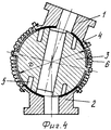
На фиг.1-3 приведена конструкция гибкого волновода, состоящего из двух звеньев-фланцев и нескольких промежуточных звеньев; на фиг.4 - вариант конструкции гибкого волновода, состоящего из двух фланцев с промежуточным звеном шарообразной формы.Figure 1-3 shows the design of a flexible waveguide, consisting of two links-flanges and several intermediate links; figure 4 is a design variant of a flexible waveguide, consisting of two flanges with an intermediate spherical shape.
Гибкий волновод позвонкового типа (фиг.1-3) состоит из двух крайних звеньев-фланцев 1 и 2, между которыми размещена цепочка из нескольких одинаковых промежуточных звеньев 3 четвертьволновой длины, которые соприкасаются друг с другом и крайними звеньями по сферическим поверхностям 4. Дроссельные зазоры Δ между подвижными звеньями обеспечивается фторопластовыми кольцами 5, установленными в дроссельных канавках. Помимо фиксации зазора Δ, они служат и для уменьшения трения между подвижными звеньями. Подвижная механическая связь звеньев обеспечивается системой цилиндрических пружин 6, размещенных в продольных пазах на общей внешней цилиндрической поверхности. Концы пружин закреплены винтами 14 на крайних звеньях 1, 2. В средней части каждого промежуточного звена пружины обжаты проволочными кольцами-хомутиками 7, которые утоплены в кольцевых проточках заподлицо с внешней цилиндрической поверхностью волновода. В точках пересечения пружин с линиями раздела звеньев сделаны цилиндрические заглубления 8 для обеспечения возможности скручивания. Эластичный гофрированный кожух 9 герметично закреплен только на крайних звеньях-фланцах 1 и 2, чтобы не ограничивать подвижность промежуточных звеньев. Сечение волноводного канала 11 средних звеньев выполнено овальным для стабилизации электрических параметров волновода при воздействии на него деформирующих факторов. Согласование со стандартным волноводом 12 на входе и выходе обеспечивается четвертьволновым трансформатором 13.A flexible waveguide of the vertebral type (Figs. 1-3) consists of two extreme links-
На фиг.4 приведен вариант малогабаритного подвижного сочленения, обладающего всеми свойствами гибкого волновода. Подвижное сочленение состоит из двух фланцев 1 и 2 и промежуточной секции 3, выполненной в виде сферы с волноводным каналом длиной в три четверти длины волны. Как и в случае гибкого волновода, подвижность сочленения обеспечивается с помощью цилиндрических пружин 6, концы которых закреплены на фланцах 1 и 2, а средняя часть - с гребнем, проходящим по “экватору” сферы. Вогнутые сферические поверхности фланцев скользят по гладкой поверхности сферы. Для улучшения электрического контакта в сфере предусмотрены дроссельные канавки 5, заполненные диэлектриком.Figure 4 shows a variant of a compact movable joint with all the properties of a flexible waveguide. The movable joint consists of two
Экспериментальные исследования макета гибкого волновода с семью промежуточными звеньями, выполненного на волноводе сечением 28,5×12,6 мм (суммарная длина 150 мм), показали, что в 15%-ной полосе частот устройство сохраняет коэффициент стоячей волны по напряжению (КСВН) входа на уровне не выше 1,25 и потери на уровне не выше 0,2 дБ при следующих деформациях:Experimental studies of a model of a flexible waveguide with seven intermediate links, performed on a waveguide with a cross section of 28.5 × 12.6 mm (total length 150 mm), showed that in a 15% frequency band the device retains the standing wave voltage coefficient (VSWR) of the input at a level not higher than 1.25 and losses at a level not higher than 0.2 dB with the following deformations:
- растяжение - до 10 мм;- stretching - up to 10 mm;
- изгиб в Н-плоскости - до 60°;- bending in the H-plane - up to 60 °;
- изгиб в Е-плоскости - до 30°;- bending in the E-plane - up to 30 °;
- скрутка - до 90°;- twist - up to 90 °;
- параллельные смещения фланцев - до 10 мм.- parallel displacements of flanges - up to 10 mm.
Claims (2)
Priority Applications (1)
| Application Number | Priority Date | Filing Date | Title |
|---|---|---|---|
| RU2003123731/09A RU2236070C1 (en) | 2003-07-31 | 2003-07-31 | Flexible waveguide |
Applications Claiming Priority (1)
| Application Number | Priority Date | Filing Date | Title |
|---|---|---|---|
| RU2003123731/09A RU2236070C1 (en) | 2003-07-31 | 2003-07-31 | Flexible waveguide |
Publications (2)
| Publication Number | Publication Date |
|---|---|
| RU2236070C1 true RU2236070C1 (en) | 2004-09-10 |
| RU2003123731A RU2003123731A (en) | 2005-02-10 |
Family
ID=33434091
Family Applications (1)
| Application Number | Title | Priority Date | Filing Date |
|---|---|---|---|
| RU2003123731/09A RU2236070C1 (en) | 2003-07-31 | 2003-07-31 | Flexible waveguide |
Country Status (1)
| Country | Link |
|---|---|
| RU (1) | RU2236070C1 (en) |
Cited By (5)
| Publication number | Priority date | Publication date | Assignee | Title |
|---|---|---|---|---|
| RU2333577C2 (en) * | 2006-09-06 | 2008-09-10 | Федеральное государственное унитарное предприятие "Государственный московский завод "Салют" | Waveguide rotator |
| RU2498465C1 (en) * | 2012-05-12 | 2013-11-10 | Открытое акционерное общество "Концерн радиостроения "Вега" | Articulated waveguide connection |
| RU2584509C2 (en) * | 2010-03-03 | 2016-05-20 | Астриум Лимитед | Waveguide |
| RU2667321C1 (en) * | 2016-12-27 | 2018-09-18 | федеральное государственное бюджетное образовательное учреждение высшего образования "Национальный исследовательский университет "МЭИ" (ФГБОУ ВО "НИУ "МЭИ") | Connector for flanges of microwave waveguides |
| RU2668627C1 (en) * | 2016-12-28 | 2018-10-02 | федеральное государственное бюджетное образовательное учреждение высшего образования "Национальный исследовательский университет "МЭИ" (ФГБОУ ВО "НИУ "МЭИ") | Connector for flanges of microwave waveguides |
Citations (4)
| Publication number | Priority date | Publication date | Assignee | Title |
|---|---|---|---|---|
| US3890583A (en) * | 1973-02-26 | 1975-06-17 | Cables De Lyon Geoffroy Delore | Flexible circular waveguide utilizing helical windings |
| US5528208A (en) * | 1993-05-12 | 1996-06-18 | Nec Corporation | Flexible waveguide tube having a dielectric body thereon |
| SU1809719A1 (en) * | 1990-06-27 | 1996-12-27 | Научно-производственное объединение прикладной механики | Flexible waveguide |
| RU2092938C1 (en) * | 1992-12-21 | 1997-10-10 | Институт физики высоких энергий | Flexible rectangular waveguide |
-
2003
- 2003-07-31 RU RU2003123731/09A patent/RU2236070C1/en not_active IP Right Cessation
Patent Citations (4)
| Publication number | Priority date | Publication date | Assignee | Title |
|---|---|---|---|---|
| US3890583A (en) * | 1973-02-26 | 1975-06-17 | Cables De Lyon Geoffroy Delore | Flexible circular waveguide utilizing helical windings |
| SU1809719A1 (en) * | 1990-06-27 | 1996-12-27 | Научно-производственное объединение прикладной механики | Flexible waveguide |
| RU2092938C1 (en) * | 1992-12-21 | 1997-10-10 | Институт физики высоких энергий | Flexible rectangular waveguide |
| US5528208A (en) * | 1993-05-12 | 1996-06-18 | Nec Corporation | Flexible waveguide tube having a dielectric body thereon |
Cited By (5)
| Publication number | Priority date | Publication date | Assignee | Title |
|---|---|---|---|---|
| RU2333577C2 (en) * | 2006-09-06 | 2008-09-10 | Федеральное государственное унитарное предприятие "Государственный московский завод "Салют" | Waveguide rotator |
| RU2584509C2 (en) * | 2010-03-03 | 2016-05-20 | Астриум Лимитед | Waveguide |
| RU2498465C1 (en) * | 2012-05-12 | 2013-11-10 | Открытое акционерное общество "Концерн радиостроения "Вега" | Articulated waveguide connection |
| RU2667321C1 (en) * | 2016-12-27 | 2018-09-18 | федеральное государственное бюджетное образовательное учреждение высшего образования "Национальный исследовательский университет "МЭИ" (ФГБОУ ВО "НИУ "МЭИ") | Connector for flanges of microwave waveguides |
| RU2668627C1 (en) * | 2016-12-28 | 2018-10-02 | федеральное государственное бюджетное образовательное учреждение высшего образования "Национальный исследовательский университет "МЭИ" (ФГБОУ ВО "НИУ "МЭИ") | Connector for flanges of microwave waveguides |
Also Published As
| Publication number | Publication date |
|---|---|
| RU2003123731A (en) | 2005-02-10 |
Similar Documents
| Publication | Publication Date | Title |
|---|---|---|
| CN108666717B (en) | A non-contact low passive intermodulation waveguide connection structure and design method | |
| RU2236070C1 (en) | Flexible waveguide | |
| Bojanic et al. | Enhanced modelling of split-ring resonators couplings in printed circuits | |
| KR102134332B1 (en) | Adapter connecting waveguide and coaxial cable with open type combination structure | |
| TW202019011A (en) | Branch-line coupler | |
| CN108649306A (en) | A kind of low passive intermodulation waveguide flange and design method | |
| CA2118901C (en) | Planar variable power divider | |
| Dahlberg et al. | Propagation characteristics of periodic structures possessing twist and polar glide symmetries | |
| FI99217C (en) | A method of tuning the buzzer network into a base station, a switching means and a bandpass filter | |
| KR101636880B1 (en) | 4 PORTS 2 SECTIONS 3-dB HYBRID COUPLER WITH ASYMMETRICAL TRANSMISSION LINES | |
| JP7129263B2 (en) | converter | |
| US3906407A (en) | Rotary wave-guide structure including polarization converters | |
| Shen et al. | Waveguide branch couplers for tight couplings | |
| US4679008A (en) | Sharp mode-transducer bend for overmoded waveguide | |
| Zhao et al. | A wideband symmetrical crossover model with analytic analysis and its millimeter-wave application | |
| Dehghani et al. | Realization of an absorptive bandpass filter based on groove gap waveguide technology | |
| US3846720A (en) | Compact microwave termination and uses thereof | |
| Marini et al. | Practical design of filters using EBG waveguides periodically loaded with metal ridges | |
| Upadhyay et al. | Development of narrowband microwave bandpass filter for Ku band | |
| JP7549057B2 (en) | Waveguide connection structure and waveguide switch using the same | |
| Jin et al. | Stub‐loaded square loop bandpass filter with equiripple response in both delay and magnitude | |
| Hussein et al. | Electromagnetic scattering by a lossy dielectric elliptic cylinder | |
| Sato et al. | Basic study for wireless power transfer to a pipeline inspection robot | |
| Collier et al. | Comparison of junctions in both dielectric guides and metallic guides above 75 GHz | |
| CN119087698B (en) | A fully polarized Fabry-Perot resonant material |
Legal Events
| Date | Code | Title | Description |
|---|---|---|---|
| PC43 | Official registration of the transfer of the exclusive right without contract for inventions |
Effective date: 20100713 |
|
| MM4A | The patent is invalid due to non-payment of fees |
Effective date: 20190801 |