RU2229373C2 - Assembling attachment for mounting elastic sealings onto basic part - Google Patents
Assembling attachment for mounting elastic sealings onto basic part Download PDFInfo
- Publication number
- RU2229373C2 RU2229373C2 RU2002112496/11A RU2002112496A RU2229373C2 RU 2229373 C2 RU2229373 C2 RU 2229373C2 RU 2002112496/11 A RU2002112496/11 A RU 2002112496/11A RU 2002112496 A RU2002112496 A RU 2002112496A RU 2229373 C2 RU2229373 C2 RU 2229373C2
- Authority
- RU
- Russia
- Prior art keywords
- petals
- housing
- pusher
- cam
- axis
- Prior art date
Links
- 238000007789 sealing Methods 0.000 title abstract description 7
- 210000000056 organ Anatomy 0.000 claims abstract description 15
- 238000000926 separation method Methods 0.000 claims abstract description 7
- 238000005096 rolling process Methods 0.000 claims description 9
- 238000000034 method Methods 0.000 abstract 1
- 239000000126 substance Substances 0.000 abstract 1
- 238000006073 displacement reaction Methods 0.000 description 1
- 230000003993 interaction Effects 0.000 description 1
Images
Landscapes
- Sealing Devices (AREA)
- Clamps And Clips (AREA)
Abstract
Description
Изобретение относится к автомобильной промышленности и может быть использовано для расширения эластичных уплотнений при надевании их на жгуты проводов.The invention relates to the automotive industry and can be used to expand elastic seals when putting them on wire harnesses.
Известны устройства для установки эластичных колец на базовые детали, содержащие деформирующий орган и привод деформирующего органа, в которых диаметр уплотнительного кольца увеличивают до размера, равного или большего диаметра уплотняемой поверхности (Патенты РФ N 904973, 973289, 1237360, кл. МПК В 23 Р 19/08).Known devices for installing elastic rings on base parts containing a deforming organ and a drive of the deforming organ, in which the diameter of the sealing ring is increased to a size equal to or greater than the diameter of the sealing surface (RF Patents N 904973, 973289, 1237360, class IPC 23 R 19 / 08).
Эти устройства сложны по конструкции и не могут быть использованы для установки эластичных уплотнений на пучок проводов.These devices are complex in design and cannot be used to install elastic seals on a bundle of wires.
Наиболее близким по конструкции к заявляемому техническому решению является сборочное приспособление для надевания эластичных деталей на жесткую деталь, содержащее корпус, деформирующий орган с лепестками, механизм развода лепестков, включающий толкатель с установленными с возможностью возвратно-поступательного перемещения в корпусе скалками, и фигурный кулачок (Патент РФ N 1625681, кл. МПК В 25 В 27/10, 27/12, 1989г.). Это приспособление принято нами за ближайший аналог.The closest in design to the claimed technical solution is an assembly device for putting on elastic parts on a rigid part containing a housing, a deforming organ with petals, a petal separation mechanism, including a pusher with rolling pins installed with the possibility of reciprocating movement in the housing, and a figured cam (Patent RF N 1625681, class IPC В 25 В 27/10, 27/12, 1989). This device is taken by us as the closest analogue.
Недостатком устройства по ближайшему аналогу является сложность конструкции и невозможность применения его для установки эластичных уплотнений на пучок проводов.The disadvantage of the device according to the closest analogue is the complexity of the design and the inability to use it to install elastic seals on a bundle of wires.
Техническое решение направлено на упрощение конструкции устройства и повышение производительности труда при сборке жгутов проводов.The technical solution is aimed at simplifying the design of the device and increasing labor productivity during the assembly of wire harnesses.
Для решения этой задачи в устройстве для установки эластичных уплотнений на базовую деталь, содержащем корпус, деформирующий орган выполненный в виде лепестков, механизм развода лепестков, включающий толкатель с закрепленными на нем скалками, установленными с возможностью возвратно-поступательного перемещения в корпусе устройства, и фигурный кулачок, согласно заявляемому техническому решению деформирующий орган выполнен в виде двух лепестков, один из которых консольно закреплен на корпусе, а другой - на съемной планке, взаимосвязанной с механизмом развода лепестков, а скалки размещены в сквозных направляющих отверстиях корпуса, и в глухих отверстиях съемной планки с возможностью перемещения в плоскости, перпендикулярной оси деформирующего органа, а толкатель взаимосвязан с приводом перемещения через фигурный кулачок, выполненный в виде прямоугольника, на двух смежных сторонах которого, предназначенных для взаимодействия с толкателем, выполнено радиусное закругление, а две другие стороны снабжены выступами-упорами, при этом фигурный кулачок закреплен на валу, ось которого равноудалена от плоскости, содержащих упорные поверхности выступов-упоров кулачка, а от рабочих сторон кулачка - на расстояния L и М, где (M-L) - расстояние, на которое разводятся лепестки, причем механизм развода лепестков размещен в полости корпуса, а вал приводится во вращение через отверстие в корпусе.To solve this problem, in a device for installing elastic seals on a base part containing a body, a deforming body made in the form of petals, a petal separation mechanism, including a pusher with rolling pins fixed on it, mounted with the possibility of reciprocating movement in the device body, and a figured cam , according to the claimed technical solution, the deforming body is made in the form of two petals, one of which is cantilever mounted on the housing, and the other on a removable bar, interconnected th with a petal separation mechanism, and rolling pins are placed in the through guide holes of the housing, and in the blind holes of the removable bar with the possibility of movement in a plane perpendicular to the axis of the deforming organ, and the pusher is interconnected with the drive of movement through a figured cam made in the form of a rectangle on two adjacent the sides of which are intended to interact with the pusher, a radial rounding is made, and the other two sides are equipped with protrusions-stops, while the figured cam is mounted on the shaft, the axis which is equidistant from the plane containing the abutment surfaces of the cam protrusions, and from the working sides of the cam - at distances L and M, where (ML) is the distance at which the petals are parted, and the mechanism for separating the petals is placed in the housing cavity, and the shaft is driven rotation through an opening in the housing.
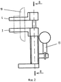
На фиг.1 показано сборочное приспособление в исходном положении (разрез по вертикальной оси).Figure 1 shows the assembly fixture in the initial position (section along the vertical axis).
На фиг.2 - сборочное приспособление, лепестки деформирующего органа на максимальном расстоянии друг от друга.Figure 2 - assembly device, the petals of the deforming organ at a maximum distance from each other.
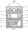
На фиг.3 - сечение А-А на фиг.1.Figure 3 is a section aa in figure 1.
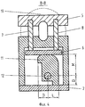
На фиг.4 - сечение В-В на фиг.2.Figure 4 - section bb in figure 2.
Устройство содержит корпус 1, основание 2, деформирующий орган, выполненный в виде двух лепестков 3 и 4, один из которых, например лепесток 3, консольно закреплен на корпусе 1, а другой - на съемной планке 5, взаимосвязанной с механизмом развода лепестков, включающим толкатель 6 закрепленными на нем скалками 7 и 8, размещенными в сквозных направляющих отверстиях 9 и 10 корпуса 1 и в глухих отверстиях съемной планки с возможностью возвратно-поступательного перемещения в плоскости, перпендикулярной оси 1 деформирующего органа. Толкатель 6 взаимосвязан с приводом перемещения через фигурный кулачок 11, закрепленный на валу 12, который через отверстие в корпусе 1 с помощью рукоятки 13 приводится во вращение. При этом механизм развода лепестков размещен в полости 14, выполненной в корпусе 1. Фигурный кулачок 11 выполнен в форме прямоугольника, две смежные стороны которого снабжены выступами-упорами 15 и 16, а на двух других сторонах, предназначенных для взаимодействия с толкателем 6, выполнено радиусное закругление 17. Ось 1 вала 12, на котором закреплен фигурный кулачок 11, удалена на расстояние D от плоскостей (на чертежах не показаны), содержащих упорные поверхности выступов-упоров 15 и 16 кулачка 11, от рабочих сторон 18 кулачка 11 - на расстояния L и М, где (M-L) - расстояние, на которое разводятся лепестки 3 и 4 деформирующего органа. Основание 2 приспособления закреплено на столе для сборки деталей (на чертежах не показан).The device comprises a
Приспособление работает следующим образом.The device works as follows.
В исходном положении лепестки 3 и 4 деформирующего органа сдвинуты вместе (см. фиг.1 и 3 прилагаемых чертежей). На лепестки 3 и 4 надевается уплотнительное кольцо 19, которое необходимо расширить для надевания на пучок проводов. При повороте рукоятки 13 по часовой стрелке на 90 градусов (до упора) рабочая поверхность 18 кулачка 11 взаимодействует с нижней поверхностью (на чертежах 3 и 4) толкателя 6. При этом вращательное движение кулачка 11 преобразуется в возвратно-поступательное перемещение толкателя 6, скалок 7 и 8 и лепестков 3 и 4. Лепестки 3 и 4 при этом расходятся, расширяя эластичное уплотнительное кольцо 19. Форма выполнения кулачка 11 позволяет фиксировать положение лепестков на максимальном расстоянии M-L друг от друга на все время сборки. Затем концы проводов, предварительно собранных в пучок и обжатых наконечниками (на чертежах не показаны), вставляются в отверстие между лепестками деформирующего органа, на которые надето уплотнительное кольцо. Поворотом рукоятки 13 на 90 градусов против часовой стрелки лепестки 3 и 4 деформирующего органа сдвигаются друг к другу. Затем уплотнительное кольцо снимается с лепестков 3 и 4 деформирующего органа и надевается на пучок проводов. Для съема собранного узла с приспособления необходимо снять съемную планку 5 со скалок 7 и 8, собранный узел снять с приспособления и надеть съемную планку 5 на скалки 7 и 8.In the initial position, the
Claims (1)
Priority Applications (1)
| Application Number | Priority Date | Filing Date | Title |
|---|---|---|---|
| RU2002112496/11A RU2229373C2 (en) | 2002-05-13 | 2002-05-13 | Assembling attachment for mounting elastic sealings onto basic part |
Applications Claiming Priority (1)
| Application Number | Priority Date | Filing Date | Title |
|---|---|---|---|
| RU2002112496/11A RU2229373C2 (en) | 2002-05-13 | 2002-05-13 | Assembling attachment for mounting elastic sealings onto basic part |
Publications (2)
| Publication Number | Publication Date |
|---|---|
| RU2002112496A RU2002112496A (en) | 2004-01-27 |
| RU2229373C2 true RU2229373C2 (en) | 2004-05-27 |
Family
ID=32678511
Family Applications (1)
| Application Number | Title | Priority Date | Filing Date |
|---|---|---|---|
| RU2002112496/11A RU2229373C2 (en) | 2002-05-13 | 2002-05-13 | Assembling attachment for mounting elastic sealings onto basic part |
Country Status (1)
| Country | Link |
|---|---|
| RU (1) | RU2229373C2 (en) |
Cited By (2)
| Publication number | Priority date | Publication date | Assignee | Title |
|---|---|---|---|---|
| CN104128908A (en) * | 2014-07-25 | 2014-11-05 | 中意凯盛(蚌埠)玻璃冷端机械有限公司 | Rubber wheel assembly device |
| RU202004U1 (en) * | 2020-03-13 | 2021-01-27 | Цзянсуская корпорация по ядерной энергетике | Mechanical seal assembly device |
Citations (3)
| Publication number | Priority date | Publication date | Assignee | Title |
|---|---|---|---|---|
| SU1237360A1 (en) * | 1980-02-05 | 1986-06-15 | Севастопольский Приборостроительный Институт | Method of assembling sealed joints |
| SU1625681A1 (en) * | 1989-01-03 | 1991-02-07 | Производственное объединение "Сибэнергомаш" | Assembly arrangement |
| SU1710329A1 (en) * | 1990-01-08 | 1992-02-07 | Научно-производственное объединение "АНИ" | Device for mounting elastic ring |
-
2002
- 2002-05-13 RU RU2002112496/11A patent/RU2229373C2/en active
Patent Citations (3)
| Publication number | Priority date | Publication date | Assignee | Title |
|---|---|---|---|---|
| SU1237360A1 (en) * | 1980-02-05 | 1986-06-15 | Севастопольский Приборостроительный Институт | Method of assembling sealed joints |
| SU1625681A1 (en) * | 1989-01-03 | 1991-02-07 | Производственное объединение "Сибэнергомаш" | Assembly arrangement |
| SU1710329A1 (en) * | 1990-01-08 | 1992-02-07 | Научно-производственное объединение "АНИ" | Device for mounting elastic ring |
Cited By (2)
| Publication number | Priority date | Publication date | Assignee | Title |
|---|---|---|---|---|
| CN104128908A (en) * | 2014-07-25 | 2014-11-05 | 中意凯盛(蚌埠)玻璃冷端机械有限公司 | Rubber wheel assembly device |
| RU202004U1 (en) * | 2020-03-13 | 2021-01-27 | Цзянсуская корпорация по ядерной энергетике | Mechanical seal assembly device |
Also Published As
| Publication number | Publication date |
|---|---|
| RU2002112496A (en) | 2004-01-27 |
Similar Documents
| Publication | Publication Date | Title |
|---|---|---|
| CN102068088B (en) | Portable object with an interchangeable bracelet or strap | |
| JPH0654125B2 (en) | Piston / cylinder assembly | |
| JP3141851U (en) | Chain coupling link and removal tool for coupling link | |
| CN1137877A (en) | Mechamism for connecting ornamental parts of wrist watch | |
| JPH01310182A (en) | Reciprocating piston type compressor and assembling method thereof | |
| RU2229373C2 (en) | Assembling attachment for mounting elastic sealings onto basic part | |
| JP6313898B1 (en) | Link mechanism and hose clip mounting jig | |
| JP3262797B2 (en) | Two-piece connecting rod for reciprocating hermetic compressor | |
| JP6854315B2 (en) | Electric tightening device | |
| JPH05196018A (en) | Device for assembling and overhauling two part | |
| KR20040035745A (en) | Boot slider | |
| CN113878524A (en) | Piston ring clamping device | |
| CN113366227B (en) | Brake for vehicle | |
| CN114484384B (en) | Detachable automatic locking structure and lighting fixture | |
| SU706588A1 (en) | Quickly detatchable connection device | |
| EP0620382A1 (en) | A quick assemblable chain link for a cable-holding chain | |
| CN209078650U (en) | For dismantling the workbench of sealing ring | |
| KR200240278Y1 (en) | Split piston pin | |
| US4863203A (en) | Seal attachment for tubing | |
| CN214643326U (en) | Sealing washer assembly fixture | |
| SU1088926A1 (en) | Apparatus for setting a set of piston rings into engine piston grooves | |
| CN222370215U (en) | Bending device | |
| KR100405246B1 (en) | Clamp apparatus | |
| CN213727205U (en) | a water outlet | |
| CN220769183U (en) | Hinge assembly and refrigerator |