RU2226652C2 - Gas-turbine engine combustion chamber - Google Patents
Gas-turbine engine combustion chamberInfo
- Publication number
- RU2226652C2 RU2226652C2 RU2002113991/06A RU2002113991A RU2226652C2 RU 2226652 C2 RU2226652 C2 RU 2226652C2 RU 2002113991/06 A RU2002113991/06 A RU 2002113991/06A RU 2002113991 A RU2002113991 A RU 2002113991A RU 2226652 C2 RU2226652 C2 RU 2226652C2
- Authority
- RU
- Russia
- Prior art keywords
- burner
- centers
- modules
- burner modules
- inner row
- Prior art date
Links
Images
Abstract
Description
Изобретение относится к газотурбинным двигателям, в частности к конструкциям кольцевых камер сгорания.The invention relates to gas turbine engines, in particular to designs of annular combustion chambers.
Известна камера сгорания, содержащая две отстоящие друг от друга кольцевые стенки, соединенные между собой в передней по потоку части этой камеры дном и ограничивающие с этим дном собственно камеру сгорания, имеющую ось симметрии, также являющуюся осью симметрии для упомянутых кольцевых стенок. Топливные форсунки, распределенные в два ряда, являющиеся концентрическими по отношению к общей оси симметрии и расположенные в отверстиях, выполненных в дне камеры сгорания, причем два ряда топливных форсунок содержат одинаковое число этих форсунок, равномерно распределенных вокруг оси симметрии, топливные форсунки внешнего ряда расположены в тех же продольных плоскостях, проходящих через ось симметрии, что и топливные форсунки внутреннего ряда [1].A combustion chamber is known, comprising two annular walls spaced apart from each other, connected to each other in the upstream part of this chamber by the bottom and limiting the combustion chamber proper having a symmetry axis, which is also a symmetry axis for said annular walls. Fuel nozzles distributed in two rows, which are concentric with respect to the common axis of symmetry and located in the holes made in the bottom of the combustion chamber, two rows of fuel nozzles containing the same number of these nozzles uniformly distributed around the axis of symmetry, the fuel nozzles of the outer row are located in the same longitudinal planes passing through the axis of symmetry as the fuel nozzles of the inner row [1].
Недостатками известной камеры сгорания являются неодинаковые расстояния от центра каждого горелочного модуля внутреннего ряда до центров двух ближайших горелочных модулей внутреннего и наружного рядов, а также расстояния от центра каждого горелочного модуля наружного ряда до центров двух ближайших горелочных модулей внутреннего ряда. Вследствие этого требуется несимметричное относительно фронтового устройства и кольцевых стенок камеры сгорания инжектирование пропорций воздуха на уровне топливных форсунок через первичные отверстия, проходы в фронтовом устройстве, отверстия разбавления и отверстия охлаждения стенок, что не обеспечивает равномерного поля давлений и температур, а также возможности повышения топливной экономичности газотурбинного двигателя. Недостатком известной конструкции является также неполное использование возможности увеличения ресурса жаровой трубы вследствие расположения топливных форсунок внешнего ряда в тех же продольных плоскостях, проходящих через ось симметрии, что и топливные форсунки внутреннего ряда. Это не обеспечивает равномерных полей температур на входе и на выходе из камеры сгорания при уменьшении потерь давления, увеличении расхода воздуха, направляемого на организацию процесса горения, и снижения расхода охлаждающего воздуха, а также не исключает появление "горячих" следов на лопатках турбины.The disadvantages of the known combustion chamber are the unequal distances from the center of each burner module of the inner row to the centers of the two nearest burner modules of the inner and outer rows, as well as the distance from the center of each burner module of the outer row to the centers of the two nearest burner modules of the inner row. As a result, injection of air proportions at the level of the fuel nozzles through the primary holes, passages in the front device, dilution holes and wall cooling holes is asymmetrical with respect to the front device and the annular walls of the combustion chamber, which does not provide a uniform pressure and temperature field, as well as the possibility of increasing fuel economy gas turbine engine. A disadvantage of the known design is also the incomplete use of the possibility of increasing the resource of the flame tube due to the location of the fuel nozzles of the outer row in the same longitudinal planes passing through the axis of symmetry as the fuel nozzles of the inner row. This does not provide uniform temperature fields at the inlet and outlet of the combustion chamber with a decrease in pressure loss, an increase in the air flow directed to the organization of the combustion process, and a decrease in the flow of cooling air, and also does not exclude the appearance of “hot” marks on the turbine blades.
Наиболее близкой к заявляемой конструкции является камера сгорания газотурбинного двигателя, в нем кольцевую жаровую трубу, включающую две отстоящие друг от друга кольцевые оболочки, соединенные в передней по потоку части этой жаровой трубы фронтовым устройством, включающим топливные форсунки, каждая из которых выполнена в виде корпуса-стойки, ориентированного в плоскости, проходящей через продольную ось жаровой трубы или рядом с этой осью, с двумя горелочными модулями, причем горелочные модули в поперечном сечении жаровой трубы образуют два концентричных ряда. Система впрыска топлива в камеру сгорания предусматривает две головки впрыска в турбореактивном двигателе, управляющую головку, обеспечивающую топливоподачу на низких режимах, и взлетную головку с взлетными форсунками в виде двух отдельных горелочных модулей, питаемых от отдельных топливных систем. Первая топливная система обеспечивает питание взлетных форсунок на форсированных режимах, а вторая топливная система питает эти форсунки, начиная с низких режимов, одновременно с питанием управляющей головки [2].Closest to the claimed design is a combustion chamber of a gas turbine engine, in it an annular flame tube, including two spaced apart annular shells connected in the upstream part of this flame tube by a front-end device comprising fuel nozzles, each of which is made in the form of a housing racks oriented in a plane passing through the longitudinal axis of the flame tube or near to this axis, with two burner modules, and burner modules in the cross section of the flame tube image comfort two concentric rows. The fuel injection system into the combustion chamber provides for two injection heads in a turbojet engine, a control head providing fuel supply at low modes, and a take-off head with take-off nozzles in the form of two separate burner modules powered by separate fuel systems. The first fuel system provides power to the take-off nozzles in forced modes, and the second fuel system supplies these nozzles, starting from low modes, simultaneously with the power to the control head [2].
Недостатком известной конструкции, принятой за прототип, является неполное использование возможности повышения топливной экономичности и ресурса газовой турбины. Это объясняется тем, что горелочные модули внешнего ряда расположены в тех же продольных или меридианных плоскостях, что и горелочные модули внутреннего ряда. При этом расстояния от центра каждого горелочного модуля внутреннего ряда до центров двух ближайших горелочных модулей внутреннего и наружного рядов, а также расстояния от центра каждого горелочного модуля наружного ряда до центров двух ближайших горелочных модулей внутреннего ряда не идентичны, а расстояния от центра каждого горелочного модуля наружного ряда до центров двух ближайших горелочных модулей внутреннего ряда не равны расстоянию между центрами горелочных модулей внутреннего ряда. В известной конструкции требуется несимметричное относительно фронтового устройства и кольцевых стенок жаровой трубы инжектирование пропорций воздуха на уровне горелочных модулей через первичные отверстия, проходы в фронтовом устройстве, отверстия разбавления и отверстия охлаждения стенок, что не обеспечивает равномерности полей температур и давлений на входе и выходе из камеры сгорания, усложняет расчет температурных полей на входе в турбину высокого давления, а также не исключает появления "горячих" следов на сопловых и рабочих лопатках турбины высокого давления, преимущественно на переходных режимах.A disadvantage of the known design adopted as a prototype is the incomplete use of the possibility of increasing fuel efficiency and the resource of a gas turbine. This is because the burner modules of the outer row are located in the same longitudinal or meridian planes as the burner modules of the inner row. The distances from the center of each burner module of the inner row to the centers of the two nearest burner modules of the inner and outer rows, as well as the distances from the center of each burner module of the outer row to the centers of the two nearest burner modules of the inner row are not identical, and the distances from the center of each burner module of the outer row to the centers of the two nearest burner modules of the inner row are not equal to the distance between the centers of the burner modules of the inner row. In the known construction, injection of air proportions at the level of the burner modules through the primary holes, passages in the front device, dilution holes and wall cooling holes is required asymmetrical with respect to the front device and the annular walls of the flame tube, which does not ensure uniform temperature and pressure fields at the inlet and outlet of the chamber combustion, complicates the calculation of temperature fields at the entrance to the high-pressure turbine, and also does not exclude the appearance of "hot" traces on nozzle and working surfaces Patk high pressure turbines, mainly in transient conditions.
Техническая задача, на решение которой направлено заявляемое изобретение, заключается в повышении топливной экономичности и ресурса газовой турбины газотурбинного двигателя путем уменьшения потерь давления, увеличения расхода воздуха, направляемого на организацию процесса горения и уменьшения расхода охлаждающего воздуха вследствие более равномерного подвода воздуха к топливу и выравнивания полей давления и температуры в передней по потоку части жаровой трубы - фронтовом устройстве.The technical problem to which the claimed invention is directed is to increase the fuel economy and resource of a gas turbine of a gas turbine engine by reducing pressure losses, increasing the air flow directed to the organization of the combustion process and reducing the flow of cooling air due to a more uniform supply of air to the fuel and leveling the fields pressure and temperature in the upstream part of the flame tube - the front device.
Сущность технического решения заключается в том, что в камере сгорания газотурбинного двигателя, содержащей корпус, в нем кольцевую жаровую трубу, включающую две отстоящие друг от друга кольцевые оболочки, соединенные между собой в передней по потоку части этой жаровой трубы фронтовым устройством, включающим топливные форсунки, каждая из которых выполнена в виде корпуса-стойки, ориентированного в плоскости, проходящей через продольную ось жаровой трубы или рядом с этой осью, с двумя горелочными модулями, каждый из которых снабжен осевым и (или) радиальным завихрителем воздуха, причем горелочные модули в поперечном сечении жаровой трубы образуют два концентричных ряда, согласно изобретению горелочные модули в каждой форсунке расположены в разных рядах по разные стороны от плоскости, проходящей через корпус-стойку топливной форсунки, при этом расстояния от центра каждого горелочного модуля внутреннего ряда до центров двух ближайших горелочных модулей внутреннего и наружного рядов идентичны, а расстояния от центра каждого горелочного модуля наружного ряда до центров двух ближайших горелочных модулей внутреннего ряда равны расстоянию между центрами горелочных модулей внутреннего ряда. Каждая топливная форсунка содержит соединенные с корпусом-стойкой стабилизаторы потока воздуха, при этом поперечное сечение наружного контура каждого стабилизатора перекрывает канал осевого завихрителя и образует щелевой канал с его входным торцом.The essence of the technical solution lies in the fact that in the combustion chamber of a gas turbine engine containing a housing, there is an annular flame tube, comprising two annular shells spaced apart, connected to each other in the upstream part of this flame tube by a front-end device including fuel nozzles, each of which is made in the form of a rack-case oriented in a plane passing through or along the longitudinal axis of the flame tube with two burner modules, each of which is equipped with an axial and (or) a radial air swirl, moreover, the burner modules in the cross section of the flame tube form two concentric rows, according to the invention, the burner modules in each nozzle are located in different rows on different sides of the plane passing through the housing of the fuel nozzle, while the distance from the center of each burner module of the inner row to the centers of the two nearest burner modules of the inner and outer rows are identical, and the distances from the center of each burner module of the outer row to the centers uh closest burners module inner row are equal to the distance between the centers of the inner row of burner modules. Each fuel nozzle contains stabilized air flow stabilizers connected to the rack body, while the cross section of the outer contour of each stabilizer overlaps the channel of the axial swirler and forms a slotted channel with its inlet end.
Расположение горелочных модулей в каждой форсунке в разных рядах по разные стороны от плоскости, проходящей через корпус-стойку топливной форсунки, при условии выполнения расстояний от центра каждого горелочного модуля внутреннего ряда до центров двух ближайших горелочных модулей внутреннего и наружного рядов идентичными, а расстояний от центра каждого горелочного модуля наружного ряда до центров двух ближайших горелочных модулей внутреннего ряда равными расстоянию между центрами горелочных модулей внутреннего ряда, повышает равномерность полей температур и давлений в передней по потоку части жаровой трубы - фронтовом устройстве за счет уменьшения потерь давления, увеличения расхода воздуха, направляемого на организацию процесса горения и уменьшения расхода охлаждающего воздуха. Это объясняется тем, что при обеспечении более равномерного поля давлений и температур в первичной зоне горения сокращается расход охлаждающего воздуха и на выходе из камеры сгорания уменьшается возможность появления "горячих" следов на сопловых и рабочих лопатках турбины высокого давления, преимущественно на переходных режимах, а также повышается расход воздуха, направляемого на организацию процесса горения, т.е. повышается топливная экономичность камеры сгорания и газотурбинного двигателя.The location of the burner modules in each nozzle in different rows on different sides of the plane passing through the rack of the fuel nozzle, provided that the distances from the center of each burner module of the inner row to the centers of the two nearest burner modules of the inner and outer rows are identical, and the distances from the center each burner module of the outer row to the centers of the two nearest burner modules of the inner row equal to the distance between the centers of the burner modules of the inner row, increases the dimensionality of the temperature and pressure fields in the upstream part of the flame tube - the front-end device by reducing pressure losses, increasing the air flow directed to the organization of the combustion process and reducing the flow of cooling air. This is explained by the fact that by providing a more uniform pressure and temperature field in the primary combustion zone, the flow of cooling air is reduced and the possibility of “hot” traces on the nozzle and working blades of a high-pressure turbine, mainly in transient conditions, is reduced the air flow directed to the organization of the combustion process increases, i.e. increases fuel efficiency of the combustion chamber and gas turbine engine.
Выполнение в каждой топливной форсунке соединенных с корпусом-стойкой стабилизаторов потока воздуха, причем поперечного сечения наружного контура каждого стабилизатора, перекрывающим канал осевого завихрителя с образованием щелевого канала с его входным торцом, дополнительно повышает равномерность подачи воздуха непосредственно на входе в осевой и (или) радиальный завихрители воздуха. Это объясняется выравниванием эпюры давления в щелевом канале между открытыми потоку поверхностями завихрителей воздуха и закрытыми от потока частями корпуса-стойки форсунки этих же завихрителей.The implementation in each fuel injector of air flow stabilizers connected to the rack housing, the cross section of the outer contour of each stabilizer overlapping the axial swirler channel with the formation of a slotted channel with its inlet end, further increases the uniformity of air supply directly at the inlet to the axial and (or) radial air swirlers. This is due to the equalization of the pressure plot in the slotted channel between the surfaces of the air swirls open to the flow and the parts of the nozzle body of the nozzle of the same swirls that are closed from the flow.
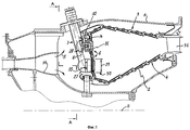
На фиг.1 изображена верхняя часть продольного сечения камеры сгорания.Figure 1 shows the upper part of a longitudinal section of the combustion chamber.
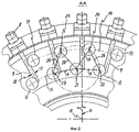
На фиг.2 - разрез А-А на фиг.1.Figure 2 is a section aa in figure 1.
Камера сгорания газотурбинного двигателя содержит корпус 1, в нем кольцевую жаровую трубу 2, включающую две отстоящие друг от друга кольцевые оболочки 3, 4, соединенные между собой в передней по потоку 5 части 6 этой жаровой трубы 2 фронтовым устройством 7, включающим топливные форсунки 8, каждая из которых выполнена в виде корпуса-стойки 9, ориентированного в плоскости 10, проходящей через продольную ось 11 жаровой трубы 2 или рядом с этой осью, с двумя горелочными модулями 12, 13, каждый из которых снабжен осевым и (или) радиальным завихрителем 14 воздуха, причем горелочные модули 12, 13 в поперечном сечении жаровой трубы 2 образуют два концентричных ряда 15, 16. Горелочные модули 12, 13 в каждой форсунке 8 расположены в разных рядах 15 или 16, по разные стороны 17 или 18 от плоскости 10, проходящей через корпус-стойку 9 топливной форсунки 8 (см.фиг.2). Расстояния 19, 20 от центра 21 каждого горелочного модуля 12 внутреннего ряда 15 до центров 22, 23, 24, 25 двух ближайших горелочных модулей 12, 13 внутреннего ряда 15 и наружного ряда 16 идентичны (см.фиг.2). Расстояния 26, 20 от центров 24, 25 каждого горелочного модуля 13 наружного ряда 16 до центров 22, 23 двух ближайших горелочных модулей 12 внутреннего ряда 15 равны расстоянию 19 между центрами 21, 22 горелочных модулей 12 внутреннего ряда 15. Каждая топливная форсунка 8 содержит соединенные с корпусом - стойкой 9 стабилизаторы 27, 28 потока 5 воздуха, при этом поперечное сечение 29 наружного контура 30 каждого стабилизатора 27, 28 перекрывает канал 31 осевого завихрителя 14 и образует щелевой канал 32 с его входным торцом 33 (см.фиг.1,2). На фиг.1 изображен также диффузор 34 с внезапным расширением и сопловой аппарат 35 газовой турбины.The combustion chamber of a gas turbine engine contains a housing 1, in it an
Камера сгорания работает следующим образом. Топливо подается в топливные форсунки 8, где, закручиваясь в распылителях форсунок, поступает в полость горения жаровой трубы 2. Одновременно сжатый компрессором воздух, обтекая наружный контур 30 стабилизаторов 27, 28 потока 5 воздуха, создает равномерную эпюру давления воздуха вниз по потоку и коаксиально поверхности 30 осевого завихрителя 14, выполненного в виде канала 31 с открытым торцом 33 на входе. При этом в окружном направлении в щелевом канале 32 эпюра давления воздуха не зависит от режимов обтекания потоков, т.к. давление выравнивается за счет определенной ширины щелевого канала 32. Поток 5 воздуха, обтекающий фронтовые устройства 7 жаровой трубы 2 и стабилизаторы 27, 28, образует равномерное поле давления в передней по потоку части 6 вследствие смещения концентричного ряда 16 горелочных модулей 13 на большое радиальное удаление от диффузора 34 с внезапным расширением. Распыливаемое горелочными модулями 12, 13 топливо при смешивании со сжатым в компрессоре воздухом образует топливовоздушную аэрозоль, которая быстро испаряется, а пары топлива сгорают по мере их смешивания с воздухом и продуктами горения. В локальных зонах стехиометрического состава смеси и обедненных составов смеси преобладают реакции кинетического горения (с возникновением цепных реакций), а в зонах обогащенной топливом смеси реакции диффузионного горения (с возникновением химических связей). В первичной зоне коэффициент избытка воздуха α составляет от 0,8 до 1,5, где: α - отношение действительного количества воздуха к теоретически необходимому для полного сгорания топлива, при этом температура продуктов горения во фронте пламени составляет 1500...2000°С. Вследствие идентичных расстояний 19 от центра 21 любого горелочного модуля 12 внутреннего ряда 15 до центров 22, 23 двух ближайших горелочных модулей 12 внутреннего ряда 15, а также расстояний 20 до центров 24, 25 наружного ряда 16, причем расстояния 20, 26 от центра 24 любого горелочного модуля 13 наружного ряда 16 до центров 21, 22 двух ближайших горелочных модулей 12 внутреннего ряда 15, равного расстоянию 19 между центрами 21, 22 горелочных модулей 12 внутреннего ряда 15, обеспечивается равномерное поле давлений и температур в поперечном сечении жаровой трубы. При этом уменьшаются потери давления, увеличивается расход воздуха, направляемого на организацию процесса горения, повышается топливная экономичность газотурбинного двигателя и увеличивается ресурс газовой турбины.The combustion chamber operates as follows. The fuel is fed into the
Источники информацииInformation sources
1. RU, патент № 2151343, F 23 R 3/04,1998 г.1. RU, patent No. 2151343, F 23
2. EP, патент № 718559, F 23 R 3/34,1996 г. - прототип.2. EP Patent No. 718559, F 23
Claims (2)
Priority Applications (1)
| Application Number | Priority Date | Filing Date | Title |
|---|---|---|---|
| RU2002113991/06A RU2226652C2 (en) | 2002-05-28 | 2002-05-28 | Gas-turbine engine combustion chamber |
Applications Claiming Priority (1)
| Application Number | Priority Date | Filing Date | Title |
|---|---|---|---|
| RU2002113991/06A RU2226652C2 (en) | 2002-05-28 | 2002-05-28 | Gas-turbine engine combustion chamber |
Publications (2)
| Publication Number | Publication Date |
|---|---|
| RU2002113991A RU2002113991A (en) | 2003-11-27 |
| RU2226652C2 true RU2226652C2 (en) | 2004-04-10 |
Family
ID=32465116
Family Applications (1)
| Application Number | Title | Priority Date | Filing Date |
|---|---|---|---|
| RU2002113991/06A RU2226652C2 (en) | 2002-05-28 | 2002-05-28 | Gas-turbine engine combustion chamber |
Country Status (1)
| Country | Link |
|---|---|
| RU (1) | RU2226652C2 (en) |
Cited By (4)
| Publication number | Priority date | Publication date | Assignee | Title |
|---|---|---|---|---|
| RU2461780C1 (en) * | 2011-05-13 | 2012-09-20 | Федеральное государственное унитарное предприятие "Центральный институт авиационного моторостроения имени П.И. Баранова" | Continuous-action combustion chamber |
| RU2468297C2 (en) * | 2007-01-23 | 2012-11-27 | Снекма | System of fuel spray to combustion chamber of gas turbine engine; combustion chamber equipped with such system, and gas turbine engine |
| RU2515909C2 (en) * | 2012-07-04 | 2014-05-20 | Федеральное государственное унитарное предприятие "Центральный институт авиационного моторостроения им. П.И. Баранова" | Gas turbine engine annular low-emission combustion chamber |
| RU2806420C1 (en) * | 2023-05-18 | 2023-10-31 | Федеральное государственное бюджетное образовательное учреждение высшего образования "Казанский национальный исследовательский технический университет им. А.Н. Туполева - КАИ" | Front device of flame tube of dual-fuel combustion chamber |
-
2002
- 2002-05-28 RU RU2002113991/06A patent/RU2226652C2/en active
Cited By (4)
| Publication number | Priority date | Publication date | Assignee | Title |
|---|---|---|---|---|
| RU2468297C2 (en) * | 2007-01-23 | 2012-11-27 | Снекма | System of fuel spray to combustion chamber of gas turbine engine; combustion chamber equipped with such system, and gas turbine engine |
| RU2461780C1 (en) * | 2011-05-13 | 2012-09-20 | Федеральное государственное унитарное предприятие "Центральный институт авиационного моторостроения имени П.И. Баранова" | Continuous-action combustion chamber |
| RU2515909C2 (en) * | 2012-07-04 | 2014-05-20 | Федеральное государственное унитарное предприятие "Центральный институт авиационного моторостроения им. П.И. Баранова" | Gas turbine engine annular low-emission combustion chamber |
| RU2806420C1 (en) * | 2023-05-18 | 2023-10-31 | Федеральное государственное бюджетное образовательное учреждение высшего образования "Казанский национальный исследовательский технический университет им. А.Н. Туполева - КАИ" | Front device of flame tube of dual-fuel combustion chamber |
Similar Documents
| Publication | Publication Date | Title |
|---|---|---|
| US10072848B2 (en) | Fuel injector with premix pilot nozzle | |
| US9239167B2 (en) | Lean burn injectors having multiple pilot circuits | |
| US7707833B1 (en) | Combustor nozzle | |
| CN102748776B (en) | Apparatus and method for combusting fuel within a gas turbine engine | |
| US8464537B2 (en) | Fuel nozzle for combustor | |
| US6935116B2 (en) | Flamesheet combustor | |
| EP2405201B1 (en) | Injection nozzle for a turbomachine | |
| CN100557318C (en) | A kind of integral fuel jet axial swirler pre-mixing preevaporated low pollution combustion chamber | |
| US9829200B2 (en) | Burner arrangement and method for operating a burner arrangement | |
| CN106461211A (en) | Combustor for gas turbine engine | |
| US7024861B2 (en) | Fully premixed pilotless secondary fuel nozzle with improved tip cooling | |
| WO2011054760A1 (en) | A cooling scheme for an increased gas turbine efficiency | |
| CN101737802A (en) | Central cavity stable fire tangential combustion chamber | |
| EP2500656B1 (en) | Gas turbine combustor having a fuel nozzle for flame anchoring | |
| CN115597088B (en) | Combustion chamber structure and combustion regulation and control method | |
| CA2845164A1 (en) | Combustor for gas turbine engine | |
| US6625971B2 (en) | Fuel nozzle producing skewed spray pattern | |
| US6813890B2 (en) | Fully premixed pilotless secondary fuel nozzle | |
| RU2226652C2 (en) | Gas-turbine engine combustion chamber | |
| US20040011042A1 (en) | Gas-turbine engine combustor | |
| RU2347144C1 (en) | Annular combustion chamber of gas turbine engine and method of its operation | |
| RU220624U1 (en) | Fuel-air burner of a gas turbine engine combustion chamber | |
| RU2285865C1 (en) | Front device for combustion chamber and method of its operation | |
| CN103797217A (en) | Method and apparatus for steam injection in a gas turbine | |
| JP2008298350A (en) | Combustion device for gas turbine engine |
Legal Events
| Date | Code | Title | Description |
|---|---|---|---|
| PD4A | Correction of name of patent owner | ||
| PD4A | Correction of name of patent owner | ||
| QB4A | Licence on use of patent |
Free format text: LICENCE FORMERLY AGREED ON 20191203 Effective date: 20191203 |