RU2222373C1 - Charging device - Google Patents
Charging device Download PDFInfo
- Publication number
- RU2222373C1 RU2222373C1 RU2002124898/12A RU2002124898A RU2222373C1 RU 2222373 C1 RU2222373 C1 RU 2222373C1 RU 2002124898/12 A RU2002124898/12 A RU 2002124898/12A RU 2002124898 A RU2002124898 A RU 2002124898A RU 2222373 C1 RU2222373 C1 RU 2222373C1
- Authority
- RU
- Russia
- Prior art keywords
- distributor
- housing
- nozzle
- pipe
- compressed gas
- Prior art date
Links
- 239000003054 catalyst Substances 0.000 abstract description 13
- 239000002245 particle Substances 0.000 abstract description 8
- 239000000463 material Substances 0.000 abstract description 5
- 239000000126 substance Substances 0.000 abstract description 3
- 238000001311 chemical methods and process Methods 0.000 abstract description 2
- 239000007787 solid Substances 0.000 description 4
- 239000008187 granular material Substances 0.000 description 3
- -1 for example Substances 0.000 description 2
- 230000015572 biosynthetic process Effects 0.000 description 1
- 239000013590 bulk material Substances 0.000 description 1
- 238000001914 filtration Methods 0.000 description 1
- 230000005484 gravity Effects 0.000 description 1
- 230000035699 permeability Effects 0.000 description 1
- 238000007670 refining Methods 0.000 description 1
Images
Landscapes
- Filling Or Discharging Of Gas Storage Vessels (AREA)
- Devices And Processes Conducted In The Presence Of Fluids And Solid Particles (AREA)
- Feeding, Discharge, Calcimining, Fusing, And Gas-Generation Devices (AREA)
Abstract
Description
Изобретение относится к аппаратам для проведения химических процессов, а именно загрузочным устройствам по загрузке сыпучего материала, например твердых гранулированных катализаторов, имеющих диаметр гранул до 20 мм и различную насыпную плотность, в контактные реакторы различного диаметра, и может найти применение в химической, нефтехимической, нефтеперерабатывающей и смежных с ними отраслях промышленности. The invention relates to apparatus for carrying out chemical processes, namely, loading devices for loading granular material, for example, solid granular catalysts having a diameter of granules up to 20 mm and different bulk density, in contact reactors of various diameters, and can find application in chemical, petrochemical, oil refining and related industries.
Известно загрузочное устройство, раскрытое в патенте RU 2040327. Данное устройство содержит цилиндрический корпус, выполненный с выходными отверстиями, соединенный с корпусом заправочный узел в виде воронки и распределитель, установленный под выходными отверстиями соосно воронке. A loading device is known, disclosed in patent RU 2040327. This device comprises a cylindrical body made with outlet openings, a filling unit in the form of a funnel connected to the body, and a distributor mounted under the outlet openings coaxially to the funnel.
К недостаткам описанного устройства можно отнести низкую однородность засыпаемых частиц катализатора по физико-механическим (насыпная плотность, порозность частиц), так и по гидродинамическим (гидравлическое сопротивление, проницаемость фильтрующего потока) характеристикам. The disadvantages of the described device can be attributed to the low uniformity of the poured catalyst particles according to the physicomechanical (bulk density, particle porosity) and hydrodynamic (hydraulic resistance, permeability of the filtering stream) characteristics.
Также известна выбранная в качестве ближайшего аналога конструкция питателя сыпучих материалов, содержащего корпус, соединенный с ним заправочный узел и распределитель. Питатель снабжен трубой для подачи сжатого газа (SU 313764). Also known is selected as the closest analogue to the design of the feeder of bulk materials containing a housing connected to it a filling unit and a distributor. The feeder is equipped with a pipe for supplying compressed gas (SU 313764).
Недостаток ближайшего аналога состоит в сложной и нерациональной компоновке основных деталей устройства, от чего избавлено заявленное решение. The disadvantage of the closest analogue is the complex and irrational layout of the main parts of the device, which eliminates the claimed solution.
Задачей изобретения является обеспечение равномерной подачи сыпучего материала с целью получения однородного по своим физико-механическим и гидродинамическим свойствам слоя частиц этого материала, например слоя частиц катализатора в промышленном реакторе. The objective of the invention is to ensure a uniform supply of granular material in order to obtain a uniform in its physicomechanical and hydrodynamic properties layer of particles of this material, for example a layer of catalyst particles in an industrial reactor.
Технический результат изобретения состоит в возможности увеличения количества загружаемого в реактор сыпучего материала, например катализатора, тем самым повышения степени его использования. The technical result of the invention consists in the possibility of increasing the amount of bulk material loaded, such as a catalyst, into the reactor, thereby increasing its utilization.
Поставленная задача и технический результат достигаются тем, что загрузочное устройство, предназначенное преимущественно для сыпучих веществ, содержит корпус с образованными в нижней его части выходными отверстиями, соединенный с корпусом заправочный узел и распределитель, установленный под выходными отверстиями соосно корпусу. Устройство содержит линию в виде трубы для подачи сжатого газа, при этом выходное отверстие указанной трубы расположено между распределителем и корпусом соосно распределителю с образованием зазора между выходным отверстием трубы и распределителем. Распределитель выполнен преимущественно в виде сменного диска, сплошного или с отверстиями. The task and the technical result are achieved in that the loading device, intended primarily for bulk solids, contains a housing with outlet openings formed in its lower part, a filling unit connected to the housing, and a distributor mounted coaxially to the housing under the outlet openings. The device contains a line in the form of a pipe for supplying compressed gas, while the outlet of the specified pipe is located between the distributor and the housing coaxially to the distributor with the formation of a gap between the outlet of the pipe and the distributor. The distributor is made mainly in the form of a removable disk, solid or with holes.
В частном воплощении данного изобретения распределитель может быть выполнен вогнутым, при этом поверхность насадки, обращенная к нему, выполняется выпуклой. Путем изменения формы обращенных друг к другу поверхностей распределителя и выполненной в виде сопла сменной насадки может меняться величина зазора между ними. Также величина зазора между выходным отверстием трубы и распределителем может регулироваться только за счет формы распределителя. In a particular embodiment of the invention, the distributor may be concave, with the surface of the nozzle facing it convex. By changing the shape of the distributor surfaces facing each other and the interchangeable nozzle made in the form of a nozzle, the gap between them can be changed. Also, the gap between the pipe outlet and the distributor can only be adjusted due to the shape of the distributor.
Выходные отверстия корпуса также могут выполняться регулируемыми по величине. The outlet openings of the housing may also be adjustable in size.
Корпус загрузочного устройства преимущественно имеет цилиндрическую форму. The housing of the loading device preferably has a cylindrical shape.
Заправочный узел может быть выполнен в виде загрузочной воронки, соединенной с корпусом трубопроводом. The filling unit can be made in the form of a loading funnel connected to the housing by a pipeline.
По меньшей мере часть трубы для подачи сжатого газа может быть расположена в корпусе соосно с насадкой и распределителем. At least a portion of the compressed gas supply pipe may be coaxially located in the housing with the nozzle and distributor.
На фиг.1 изображено загрузочное устройство. Figure 1 shows the boot device.
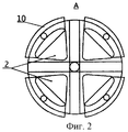
На фиг.2 - вид А по фиг.1. Figure 2 is a view A of figure 1.
Загрузочное устройство для сыпучих веществ, например катализаторов, в преимущественном варианте выполнения (фиг.1) содержит цилиндрический корпус 1 с регулируемыми выходными отверстиями 2 (фиг.2). Под выходными отверстиями соосно корпусу прикреплен распределительный диск 3. Распределитель сменный и в зависимости от размеров катализатора может иметь различную форму и размеры. По центру диска из корпуса выведена труба 4 с насадкой 5 на конце. Между диском 3 и насадкой образован регулируемый в зависимости от размера частиц катализатора зазор 6. Загрузочный узел состоит из воронки 7, присоединенной к трубопроводу 8. The loading device for bulk solids, such as catalysts, in an advantageous embodiment (FIG. 1) comprises a cylindrical housing 1 with adjustable outlet openings 2 (FIG. 2). Under the outlet openings, a distribution disk 3 is attached coaxially to the housing. The distributor is replaceable and, depending on the size of the catalyst, can have various shapes and sizes. In the center of the disk, a pipe 4 with a nozzle 5 at the end is withdrawn from the housing. A gap 6 is formed between the disk 3 and the nozzle, depending on the size of the catalyst particles. The loading unit consists of a funnel 7 connected to the pipeline 8.
Устройство работает следующим образом. The device operates as follows.
Корпус 1 загрузочного устройства, выполненный с выходными отверстиями 2, распределительный диск 3, труба 4 с насадкой 5 закрепляются в реакторе 9 на определенной высоте от его дна таким образом, чтобы между насадкой и диском образовался зазор 6. Катализатор подается к загрузочному устройству через воронку 7 по трубопроводу 8 под действием силы тяжести. The housing 1 of the loading device, made with
Катализатор через выходные отверстия падает на диск. Величина выходных отверстий 2 может регулироваться заглушками 10 (фиг.2). The catalyst through the outlet holes falls on the disk. The size of the
Сжатый до 2÷5 атм воздух или другой газ поступает по трубе 4 и выходит в зазор между диском и насадкой, равномерно расширяясь, подхватывает частицы катализатора и равномерно распределяет их по сечению реактора на определенной высоте над формируемым слоем 11. Потом частицы свободно падают вниз. Высота падения выбирается в зависимости от прочностных характеристик катализатора. Насадка меняется в зависимости от формы распределителя, т.е. при использовании плоского диска ее поверхность, обращенная к диску, выполнена плоской, а в варианте выполнения распределителя вогнутым - повторяет (эквидистантна) эту поверхность, т.е. выгнута в сторону распределителя. Compressed to 2 ÷ 5 atm air or other gas enters through the pipe 4 and leaves the gap between the disk and the nozzle, expanding uniformly, picks up the catalyst particles and evenly distributes them along the reactor cross section at a certain height above the formed layer 11. Then the particles freely fall down. The drop height is selected depending on the strength characteristics of the catalyst. The nozzle changes depending on the shape of the distributor, i.e. when using a flat disk, its surface facing the disk is made flat, and in the embodiment of the distributor concave, it repeats (equidistant) this surface, i.e. curved towards the distributor.
Давление подаваемого газа выбирается в зависимости от диаметра реактора, веса и размеров катализатора. The pressure of the feed gas is selected depending on the diameter of the reactor, the weight and size of the catalyst.
Claims (8)
Priority Applications (1)
| Application Number | Priority Date | Filing Date | Title |
|---|---|---|---|
| RU2002124898/12A RU2222373C1 (en) | 2002-09-19 | 2002-09-19 | Charging device |
Applications Claiming Priority (1)
| Application Number | Priority Date | Filing Date | Title |
|---|---|---|---|
| RU2002124898/12A RU2222373C1 (en) | 2002-09-19 | 2002-09-19 | Charging device |
Publications (2)
| Publication Number | Publication Date |
|---|---|
| RU2222373C1 true RU2222373C1 (en) | 2004-01-27 |
| RU2002124898A RU2002124898A (en) | 2004-03-27 |
Family
ID=32091720
Family Applications (1)
| Application Number | Title | Priority Date | Filing Date |
|---|---|---|---|
| RU2002124898/12A RU2222373C1 (en) | 2002-09-19 | 2002-09-19 | Charging device |
Country Status (1)
| Country | Link |
|---|---|
| RU (1) | RU2222373C1 (en) |
Cited By (2)
| Publication number | Priority date | Publication date | Assignee | Title |
|---|---|---|---|---|
| RU191404U1 (en) * | 2019-02-25 | 2019-08-05 | Закрытое акционерное общество Научно-технический центр "Технология, экспертиза и надежность" | Granular particle feeder for contact reactors |
| RU209797U1 (en) * | 2021-10-12 | 2022-03-23 | Общество с ограниченной ответственностью "Нефтехимремонт" | Loader for granular particles for contact reactors |
Citations (5)
| Publication number | Priority date | Publication date | Assignee | Title |
|---|---|---|---|---|
| US4029364A (en) * | 1975-07-07 | 1977-06-14 | Interliz Anstalt | Device for loading air with a controllable amount of a granular or powdery material |
| US4277205A (en) * | 1978-06-19 | 1981-07-07 | Saint Gobain Industries | Apparatus for distribution of solid particles |
| US4820108A (en) * | 1986-04-08 | 1989-04-11 | Gebruder Weiss K.G. | Arrangement for the essentially uniform level placement of bulk material in an upright circular cylindrical vessel |
| SU1579879A1 (en) * | 1986-11-26 | 1990-07-23 | Предприятие П/Я Г-4302 | Method of loading loose material into container |
| US5296202A (en) * | 1984-12-07 | 1994-03-22 | Chevron Research And Technology Co. | Apparatus for uniformly loading particulate material into cylindrical beds |
-
2002
- 2002-09-19 RU RU2002124898/12A patent/RU2222373C1/en not_active IP Right Cessation
Patent Citations (5)
| Publication number | Priority date | Publication date | Assignee | Title |
|---|---|---|---|---|
| US4029364A (en) * | 1975-07-07 | 1977-06-14 | Interliz Anstalt | Device for loading air with a controllable amount of a granular or powdery material |
| US4277205A (en) * | 1978-06-19 | 1981-07-07 | Saint Gobain Industries | Apparatus for distribution of solid particles |
| US5296202A (en) * | 1984-12-07 | 1994-03-22 | Chevron Research And Technology Co. | Apparatus for uniformly loading particulate material into cylindrical beds |
| US4820108A (en) * | 1986-04-08 | 1989-04-11 | Gebruder Weiss K.G. | Arrangement for the essentially uniform level placement of bulk material in an upright circular cylindrical vessel |
| SU1579879A1 (en) * | 1986-11-26 | 1990-07-23 | Предприятие П/Я Г-4302 | Method of loading loose material into container |
Cited By (2)
| Publication number | Priority date | Publication date | Assignee | Title |
|---|---|---|---|---|
| RU191404U1 (en) * | 2019-02-25 | 2019-08-05 | Закрытое акционерное общество Научно-технический центр "Технология, экспертиза и надежность" | Granular particle feeder for contact reactors |
| RU209797U1 (en) * | 2021-10-12 | 2022-03-23 | Общество с ограниченной ответственностью "Нефтехимремонт" | Loader for granular particles for contact reactors |
Also Published As
| Publication number | Publication date |
|---|---|
| RU2002124898A (en) | 2004-03-27 |
Similar Documents
| Publication | Publication Date | Title |
|---|---|---|
| EP2175953B1 (en) | A method and device for cleaning non-fixed media filters | |
| UA95132C2 (en) | Device for removal of fluid media and/or solid substances | |
| US20120211438A1 (en) | Filtering medium and method for contacting solids containing feeds for chemical reactors | |
| AU6145394A (en) | Apparatus and method for wetting powder | |
| KR20090080937A (en) | Two-step method for rapid formation of pellets | |
| RU2222373C1 (en) | Charging device | |
| WO2005028978A1 (en) | Method and apparatus for heat treatment of particulates in an electrothermal fluidized bed furnace and resultant products | |
| CN113795444B (en) | Powder distribution device and powder distribution method | |
| RU28832U1 (en) | Boot device | |
| HU184208B (en) | Feeder | |
| AU2012100264A4 (en) | Flotation device | |
| JP4859689B2 (en) | Method for producing sheet-like porous body | |
| CN111773916B (en) | Suspension bed flue gas desulfurization device and suspension bed flue gas desulfurization system | |
| CA1204276A (en) | Gas distributor for fluidized beds | |
| RU2252067C1 (en) | Method of loading of catalysts in reactors of technological installations | |
| RU191404U1 (en) | Granular particle feeder for contact reactors | |
| CN103201202B (en) | Powder distribution device | |
| HU202127B (en) | Device for producing granules by rolling-layer technology | |
| JP6970398B1 (en) | Granule supply device and granular material supply method | |
| WO2007136502A1 (en) | Plug-flow method and apparatus for operating a curvilinear pressure vessel where transport phenomena occur | |
| CA1169233A (en) | Apparatus and method for transferring solids | |
| JP6970397B1 (en) | Granule supply device and granular material supply method | |
| KR100818768B1 (en) | Dispersion Plates of Fluidized Bed Devices | |
| RU1801610C (en) | Air-operated screw feeder for powder materials | |
| SU1719834A1 (en) | Apparatus for thermally processing clotting materials |
Legal Events
| Date | Code | Title | Description |
|---|---|---|---|
| MM4A | The patent is invalid due to non-payment of fees |
Effective date: 20080920 |
|
| NF4A | Reinstatement of patent |
Effective date: 20100427 |
|
| MM4A | The patent is invalid due to non-payment of fees |
Effective date: 20150920 |