RU2219373C1 - Electric centrifugal pumping unit - Google Patents
Electric centrifugal pumping unit Download PDFInfo
- Publication number
- RU2219373C1 RU2219373C1 RU2002124497A RU2002124497A RU2219373C1 RU 2219373 C1 RU2219373 C1 RU 2219373C1 RU 2002124497 A RU2002124497 A RU 2002124497A RU 2002124497 A RU2002124497 A RU 2002124497A RU 2219373 C1 RU2219373 C1 RU 2219373C1
- Authority
- RU
- Russia
- Prior art keywords
- pumping unit
- electric centrifugal
- working stages
- centrifugal pumping
- holes
- Prior art date
Links
- 238000005086 pumping Methods 0.000 title abstract description 6
- 238000009434 installation Methods 0.000 claims description 5
- 239000000696 magnetic material Substances 0.000 claims description 4
- 230000000694 effects Effects 0.000 abstract description 2
- 239000000126 substance Substances 0.000 abstract 1
- 238000004519 manufacturing process Methods 0.000 description 6
- 238000000034 method Methods 0.000 description 4
- 241000566515 Nedra Species 0.000 description 3
- 239000003129 oil well Substances 0.000 description 3
- 238000010586 diagram Methods 0.000 description 2
- 238000005516 engineering process Methods 0.000 description 2
- 239000012530 fluid Substances 0.000 description 2
- 230000000712 assembly Effects 0.000 description 1
- 238000000429 assembly Methods 0.000 description 1
- 230000015572 biosynthetic process Effects 0.000 description 1
- 239000003153 chemical reaction reagent Substances 0.000 description 1
- 238000005553 drilling Methods 0.000 description 1
- 239000012535 impurity Substances 0.000 description 1
- 239000007788 liquid Substances 0.000 description 1
- 239000013081 microcrystal Substances 0.000 description 1
- 230000008439 repair process Effects 0.000 description 1
- 150000003839 salts Chemical class 0.000 description 1
Images
Landscapes
- Structures Of Non-Positive Displacement Pumps (AREA)
Abstract
Description
Изобретение относится к насосным установкам, предназначенным для подъема жидкостей с больших глубин, например из скважин, в частности к агрегатам двигатель-насос, расположенным на большой глубине, а именно к скважинным установкам электроцентробежных насосов (далее УЭЦН).The invention relates to pumping units intended for lifting liquids from great depths, for example from wells, in particular to engine-pump assemblies located at great depths, and in particular to downhole installations of electric centrifugal pumps (hereinafter ESP).
Известен метод акустического воздействия для предотвращения солеотложений (см. ИБРАГИМОВ Г.З., СОРОКИН В.А., ХИСАМУТДИНОВ Н.И. Химические реагенты для добычи нефти, Москва, Недра, 1986, с. 148-149).The known method of acoustic exposure to prevent scaling (see Ibrahimov G.Z., Sorokin V.A., Khisamutdinov N.I. Chemical reagents for oil production, Moscow, Nedra, 1986, pp. 148-149).
Однако такой метод имеет существенные недостатки, заключающиеся в следующем. Реализация известного метода вызывает затруднения при его использовании в скважине на глубине из-за сравнительно малого диаметра скважины (см. СЕРЕДА Н.Г., СОЛОВЬЕВ Е.М. Бурение нефтяных и газовых скважин, Москва, Недра, 1974, с. 6-7). Поскольку в настоящее время наружные диаметры эксплуатационных колонн нефтяных скважин варьируют в пределах 114-168 мм, то становятся очевидным затруднения конструктивного исполнения для акустического воздействия. Кроме этого, усложняется начинка внутрискважинного оборудования, что, несомненно, вызывает снижение технологического эффекта процесса добычи нефти.However, this method has significant disadvantages, which are as follows. The implementation of the known method causes difficulties when it is used in the well at a depth due to the relatively small diameter of the well (see Sereda N.G., Soloviev E.M. Oil and Gas Well Drilling, Moscow, Nedra, 1974, pp. 6-7 ) Since at present the external diameters of oil production casing strings vary between 114-168 mm, the design difficulties for acoustic impact become apparent. In addition, the filling of downhole equipment is complicated, which undoubtedly causes a decrease in the technological effect of the oil production process.
Наиболее близким аналогом к изобретению является электроцентробежная насосная установка, содержащая погружной электродвигатель, гидрозащиту, опорную пяту и рабочие ступени многоступенчатого насоса и кабельную линию, спускаемые на насосно-компрессорных трубах в скважину (см. МИРЗАДЖАНЗАДЕ А.Х. и др. Технология и техника добычи нефти. Москва, Недра, 1986, с.166-169).The closest analogue to the invention is an electric centrifugal pump installation containing a submersible electric motor, hydraulic protection, a support heel and working stages of a multistage pump and a cable line, lowered on tubing into a well (see MIRZAJANZADE A.Kh. et al. Production technology and technology Oil, Moscow, Nedra, 1986, p.166-169).
Однако известное техническое решение имеет следующий существенный недостаток. В процессе добычи нефти из пластовой продукции в УЭЦН отлагаются неорганические соли, которые возникают при определенных термодинамических и физико-технических условиях. Отложения вызывают снижение надежности УЭЦН, уменьшают ее производительность, приводят к остановке нефтяной скважины. В результате внутрискважинное оборудование приходится поднимать на поверхность и спускать новую УЭЦН. В итоге снижается межремонтный период нефтяной скважины, оборудованной электроцентробежным насосом.However, the known technical solution has the following significant drawback. In the process of oil production from reservoir products in ESP, inorganic salts are deposited that occur under certain thermodynamic and physical-technical conditions. Deposits cause a decrease in the reliability of the ESP, reduce its productivity, lead to the shutdown of the oil well. As a result, the downhole equipment has to be raised to the surface and lowered a new ESP. As a result, the overhaul period of an oil well equipped with an electric centrifugal pump is reduced.
Изобретение направлено на повышение эффективности работы насосной установки и увеличение срока ее эксплуатации.The invention is aimed at improving the efficiency of the pumping unit and increasing its life.
Технический результат достигается тем, что в электроцентробежной насосной установке, содержащей погружной электродвигатель, гидрозащиту, опорную пяту и рабочие ступени многоступенчатого насоса, согласно изобретению перед рабочими ступенями со стороны опорной пяты установлено устройство для создания виброакустической волны, состоящее из неподвижной части с отверстиями и вращающегося диска, выполненных из немагнитного материала, в тела которых вмонтированы постоянные магниты разноименными полюсами, расположенными один напротив другого.The technical result is achieved by the fact that in an electric centrifugal pump installation comprising a submersible electric motor, hydroprotection, supporting heel and working stages of a multi-stage pump, according to the invention, a device for generating a vibro-acoustic wave consisting of a fixed part with holes and a rotating disk is installed in front of the working stages from the side of the supporting heel. made of non-magnetic material, in the bodies of which are mounted permanent magnets with opposite poles, located one opposite to each other gogo.
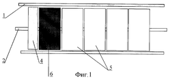
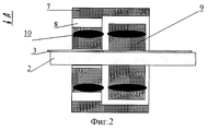
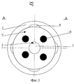
На фиг.1 показана схема местоположения устройства, создающего вибрирующие импульсы в УЭЦН; на фиг.2 - схема устройства для создания виброакустической волны; на фиг.3 - вид по стрелке А на фиг.2.Figure 1 shows the location diagram of a device that creates vibrating pulses in the ESP; figure 2 - diagram of a device for creating a vibroacoustic wave; figure 3 is a view along arrow A in figure 2.
Электроцентробежная насосная установка содержит погружной электродвигатель и гидрозащиту (не показаны). Внутри корпуса 1 насоса на валу 2 со шпонкой 3 размещены опорная пята 4, рабочие ступени 5 многоступенчатого насоса, устройство 6 для создания виброакустической волны, состоящее из неподвижной части 7 с отверстиями 8 и вращающегося диска 9. Неподвижная часть 7 и диск 9 выполнены из немагнитного материала и в их тела вмонтированы постоянные магниты 10 разноименными полюсами, расположенными один напротив другого.The electric centrifugal pump installation includes a submersible motor and hydraulic protection (not shown). Inside the pump housing 1, on the
Изобретение реализуется следующим образом.The invention is implemented as follows.
Пластовая продукция скважины (не показана) поступает в корпус 1 УЭЦН со стороны опорной пяты 4 и проходит через отверстия 8 неподвижной части 7 устройства 6, вращающийся диск 9 которого смонтирован на валу 2 с помощью шпонки 3. Устройство для создания виброакустической волны установлено вместо одной рабочей ступени 5 насоса. При вращении вала 2 вращается диск 9 устройства 6, выполненного из немагнитного материала. Разноименные полюса магнитов 10, вращаясь, притягиваются при нахождении один напротив другого. Количество полюсов магнитов 10 на неподвижной части 7 и диске 9 одинаковое, и они вмонтированы один напротив другого на одной линии. Совпадая, полюса магнитов 10 притягиваются, притяжение ослабевает при несовпадении полюсов магнитов 10 неподвижной части 7 и диска 9 устройства 6. Таким образом, в системе УЭЦН, в ее насосной части создается виброакустическая волна, способствующая интенсивному образованию в объеме пластовой продукции микрокристаллов, вынос которых обеспечивается потоком жидкости. Кроме этого, пластовая продукция, проходя через отверстия 8, подвергается воздействию магнитного поля от полюсов магнитов 10 диска 9 устройства 6. Примеси, находящиеся в пластовой продукции, подвергаясь магнитному воздействию, становятся более рыхлыми, что способствует их выносу потоком жидкости.The well production (not shown) enters the ESP body 1 from the side of the supporting
Использование изобретения приведет к увеличению межремонтного периода работы нефтяной скважины, количества добытой нефти из скважины, оборудованной УЭЦН, снижению затрат на себестоимость добычи одной тонны нефти из-за сокращения числа ремонтов скважины.The use of the invention will lead to an increase in the overhaul period of an oil well, the amount of oil produced from a well equipped with an ESP, lower costs for the cost of producing one ton of oil due to a reduction in the number of well repairs.
Claims (1)
Priority Applications (1)
| Application Number | Priority Date | Filing Date | Title |
|---|---|---|---|
| RU2002124497A RU2219373C1 (en) | 2002-09-16 | 2002-09-16 | Electric centrifugal pumping unit |
Applications Claiming Priority (1)
| Application Number | Priority Date | Filing Date | Title |
|---|---|---|---|
| RU2002124497A RU2219373C1 (en) | 2002-09-16 | 2002-09-16 | Electric centrifugal pumping unit |
Publications (1)
| Publication Number | Publication Date |
|---|---|
| RU2219373C1 true RU2219373C1 (en) | 2003-12-20 |
Family
ID=32067073
Family Applications (1)
| Application Number | Title | Priority Date | Filing Date |
|---|---|---|---|
| RU2002124497A RU2219373C1 (en) | 2002-09-16 | 2002-09-16 | Electric centrifugal pumping unit |
Country Status (1)
| Country | Link |
|---|---|
| RU (1) | RU2219373C1 (en) |
Cited By (1)
| Publication number | Priority date | Publication date | Assignee | Title |
|---|---|---|---|---|
| RU2547681C1 (en) * | 2014-03-07 | 2015-04-10 | Акционерное общество "Новомет-Пермь"(АО"Новомет- Пермь") | Submersible multistage pump for oil production under conditions complicated by salt deposits |
Citations (3)
| Publication number | Priority date | Publication date | Assignee | Title |
|---|---|---|---|---|
| SU1285208A1 (en) * | 1985-08-13 | 1987-01-23 | Ивано-Франковский Институт Нефти И Газа | Gas lift |
| DE19701993A1 (en) * | 1997-01-22 | 1998-07-23 | Eugen Dr Schmidt | Coolant pump for motor vehicles |
| US6144020A (en) * | 1998-05-19 | 2000-11-07 | Usui Kokusai Sangyo Kaisha Limited | Apparatus for simultaneously generating a fluid flow and heating the flowing fluid |
-
2002
- 2002-09-16 RU RU2002124497A patent/RU2219373C1/en not_active IP Right Cessation
Patent Citations (3)
| Publication number | Priority date | Publication date | Assignee | Title |
|---|---|---|---|---|
| SU1285208A1 (en) * | 1985-08-13 | 1987-01-23 | Ивано-Франковский Институт Нефти И Газа | Gas lift |
| DE19701993A1 (en) * | 1997-01-22 | 1998-07-23 | Eugen Dr Schmidt | Coolant pump for motor vehicles |
| US6144020A (en) * | 1998-05-19 | 2000-11-07 | Usui Kokusai Sangyo Kaisha Limited | Apparatus for simultaneously generating a fluid flow and heating the flowing fluid |
Non-Patent Citations (2)
| Title |
|---|
| W0 02/04816 A1, 17.01.2002. * |
| МИРЗАДЖАНЗАДЕ А.Х. Технология и техника добычи нефти. - М.: Недра, 1986, с.166-169. * |
Cited By (1)
| Publication number | Priority date | Publication date | Assignee | Title |
|---|---|---|---|---|
| RU2547681C1 (en) * | 2014-03-07 | 2015-04-10 | Акционерное общество "Новомет-Пермь"(АО"Новомет- Пермь") | Submersible multistage pump for oil production under conditions complicated by salt deposits |
Similar Documents
| Publication | Publication Date | Title |
|---|---|---|
| US20220243570A1 (en) | Motorized pump | |
| RU2447262C2 (en) | Method, device and magnet for magnetic treatment of fluids | |
| US10941778B2 (en) | Motorized pump | |
| RU2156379C2 (en) | System for recovery of fluid medium mainly oil and water, from deep underwater fields | |
| CA2908848C (en) | Downhole electric submersible pump with hydrodynamic bearing | |
| RU169892U1 (en) | Hydrodynamic device of an electric centrifugal pump for magnetic processing of well fluid | |
| CA2938369C (en) | Down-hole gas and solids separator utilized in production hydrocarbons | |
| WO2012054512A1 (en) | Apparatus and method for producing electric power from injection of water into a downhole formation | |
| RU2219373C1 (en) | Electric centrifugal pumping unit | |
| US2710579A (en) | Deep-well pumps | |
| RU2230181C2 (en) | Immersible centrifugal pumping device | |
| RU2298641C2 (en) | Method for oil-producing well cleaning | |
| CN105074121B (en) | Artificial lift system with bottom mounted screw motor for extracting hydrocarbons | |
| RU2081998C1 (en) | Method for releasing surplus pressure from intertube space in operating immersed electric pumps | |
| RU2278959C2 (en) | Submersible pumping installation for oil production | |
| CN209621245U (en) | Vibration reducer and oil well pump assembly | |
| RU2346146C1 (en) | System meant for magnetic processing of fluid in well equipped with electric centrifugal pump with submersible electric motor (versions) | |
| Drozdov et al. | Application of Linear Valve Submersible Electric Motors in Oil Production Units for Marginal Wells | |
| RU157504U1 (en) | STEP GUIDE DEVICE FOR SUBMERSIBLE MULTI-STAGE ELECTRIC CENTRIFUGAL PUMP | |
| RU7445U1 (en) | CENTRIFUGAL PUMP GAS SEPARATOR FOR OIL PRODUCTION FROM WELLS | |
| RU2034132C1 (en) | Method for production of oil from horizontal wells | |
| RU2321740C2 (en) | Method and device for well testing with the use of submersed pumping equipment | |
| RU2811633C1 (en) | Rod pump with cathodic protection | |
| CN222702216U (en) | A high temperature resistant sealing device for a flameproof submersible sand removal electric pump for mining | |
| RU2149991C1 (en) | Device for treatment of well gas-fluid mixture |
Legal Events
| Date | Code | Title | Description |
|---|---|---|---|
| MM4A | The patent is invalid due to non-payment of fees |
Effective date: 20070917 |