RU2219086C2 - Crawler vehicle track-carrying wheel - Google Patents
Crawler vehicle track-carrying wheel Download PDFInfo
- Publication number
- RU2219086C2 RU2219086C2 RU2001114122A RU2001114122A RU2219086C2 RU 2219086 C2 RU2219086 C2 RU 2219086C2 RU 2001114122 A RU2001114122 A RU 2001114122A RU 2001114122 A RU2001114122 A RU 2001114122A RU 2219086 C2 RU2219086 C2 RU 2219086C2
- Authority
- RU
- Russia
- Prior art keywords
- longitudinal
- shaft
- axis
- radial
- roller
- Prior art date
Links
- 230000000694 effects Effects 0.000 abstract description 2
- 238000005461 lubrication Methods 0.000 abstract description 2
- 230000003247 decreasing effect Effects 0.000 abstract 1
- 239000000126 substance Substances 0.000 abstract 1
- 238000004642 transportation engineering Methods 0.000 abstract 1
- 239000000314 lubricant Substances 0.000 description 7
- 239000003921 oil Substances 0.000 description 7
- 239000012530 fluid Substances 0.000 description 3
- 230000001050 lubricating effect Effects 0.000 description 3
- 239000010687 lubricating oil Substances 0.000 description 2
- 239000004519 grease Substances 0.000 description 1
- 230000020169 heat generation Effects 0.000 description 1
- 238000011089 mechanical engineering Methods 0.000 description 1
- 238000005086 pumping Methods 0.000 description 1
Images
Landscapes
- Rolling Contact Bearings (AREA)
Abstract
Description
Изобретение относится к транспортному машиностроению, а именно к гусеничным транспортным средствам. The invention relates to a transport mechanical engineering, namely to tracked vehicles.
Известен опорный каток для гусеничных транспортных средств, содержащий ролик, установленный посредством подшипникового узла на неподвижной оси, имеющей в верхней части продольную лыску, с масляной ванной во внутренней полости, соединенной радиальными отверстиями с подшипниковым узлом и каналами - с торцовыми уплотнениями (патент США 3910128, В 62 D 55/14, 1975 г.) Радиальные отверстия, через которые смазочный материал поступает к подшипниковому узлу и торцовым уплотнениям, расположены в горизонтальной плоскости. A track roller for caterpillar vehicles is known, comprising a roller mounted by means of a bearing assembly on a fixed axis having a longitudinal flange in the upper part, with an oil bath in the inner cavity connected by radial holes to the bearing assembly and channels with mechanical seals (US patent 3910128, In 62 D 55/14, 1975) The radial holes through which the lubricant enters the bearing assembly and mechanical seals are located in a horizontal plane.
Недостатком данного катка является то, что смазочный материал, вследствие расположения радиальных отверстий в горизонтальной плоскости, не всегда поступает к подшипниковому узлу с достаточной интенсивностью, что вызывает местные разрывы масляной пленки на поверхностях трения. Этот недостаток наиболее ярко проявляется в момент смены направления вращения катка и при работе катка с маслом повышенной вязкости, например, в условиях низких температур окружающего воздуха. The disadvantage of this roller is that the lubricant, due to the location of the radial holes in the horizontal plane, does not always reach the bearing assembly with sufficient intensity, which causes local ruptures of the oil film on the friction surfaces. This disadvantage is most pronounced at the time of changing the direction of rotation of the roller and during operation of the roller with oil of high viscosity, for example, at low ambient temperatures.
Известен также опорный каток для гусеничных машин, содержащий ролик, установленный посредством подшипникового узла на неподвижной оси с продольными лысками, снабженной в верхней части резервуаром для смазочной жидкости, и торцовые уплотнения, в котором резервуар для смазочной жидкости выполнен в виде вогнутой U-образной в поперечном сечении выемки с дном, расположенным ниже горизонтальной плоскости, проходящей через ось катка, и сообщен с нижней частью подшипникового узла выполненными в оси попарно расходящимися наклонными радиальными каналами, выходы наружу которых размещены на продольных лысках, а выходы в резервуар для смазочной жидкости - выше дна выемки (патент РФ 2090427, В 62 D 55/14, 1995 г.). A support roller for tracked vehicles is also known, comprising a roller mounted by means of a bearing assembly on a fixed axis with longitudinal flats provided in the upper part with a reservoir for lubricating fluid, and mechanical seals in which the reservoir for lubricating fluid is made in the form of a concave U-shaped transverse a cross-section of a recess with a bottom located below the horizontal plane passing through the axis of the roller, and communicated with the lower part of the bearing unit, made in the axis, pairwise diverging, inclined radial and channels, the exits of which are placed on the longitudinal flats, and the exits to the reservoir for lubricating fluid are above the bottom of the recess (RF patent 2090427, B 62 D 55/14, 1995).
Недостатком данного катка является то, что для подвода смазки из резервуара в зону трения использованы каналы, выходы которых наружу расположены в наклонных продольных лысках оси, а такое расположение лысок существенно снижает эффективную контактную поверхность оси, воспринимающую радиальные нагрузки, и приводит к повышению износа подшипникового узла. The disadvantage of this roller is that for supplying lubricant from the reservoir to the friction zone, channels are used, the outlets of which are outwardly located in the inclined longitudinal flats of the axis, and this arrangement of the flats significantly reduces the effective contact surface of the axis perceiving radial loads, and leads to increased wear of the bearing assembly .
Технический результат, на достижение которого направлено предложение, заключается в уменьшении нагруженности подшипникового узла за счет увеличения контактной площади оси, при обеспечении интенсивной смазки трущихся поверхностей и, следовательно, повышении надежности опорного катка. The technical result, the achievement of which the proposal is directed, is to reduce the load of the bearing assembly by increasing the contact area of the axis, while providing intensive lubrication of the rubbing surfaces and, therefore, increasing the reliability of the track roller.
Указанный результат достигается тем, что в опорном катке, содержащем ролик, установленный посредством торцевых и радиальных подшипников скольжения на неподвижной оси с масляным резервуаром, имеющей продольные лыски и радиальные отверстия, подведенные к торцевым подшипникам, масляный резервуар выполнен в виде открытой кольцевой полости, расположенной в средней части оси, и соединен с продольным каналом оси дополнительными радиальными отверстиями, при этом дополнительные радиальные отверстия могут быть расположены диаметрально противоположно в вертикальной плоскости, а их диаметр не должен быть менее 4 мм. This result is achieved by the fact that in the support roller containing a roller mounted by means of end and radial plain bearings on a fixed axis with an oil reservoir having longitudinal flats and radial openings led to end bearings, the oil reservoir is made in the form of an open annular cavity located in the middle part of the axis, and is connected to the longitudinal channel of the axis by additional radial holes, while additional radial holes can be diametrically opposed opolozhno in a vertical plane, and their diameter should not be less than 4 mm.
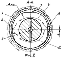
Сущность изобретения поясняется чертежами, где на фиг.1 изображен опорный каток для гусеничных машин, продольный вертикальный разрез; на фиг. 2 - сечение А-А на фиг. 1. The invention is illustrated by drawings, where figure 1 shows a track roller for tracked vehicles, a longitudinal vertical section; in FIG. 2 is a section AA in FIG. 1.
Опорный каток для гусеничных машин содержит ролик 1, установленный посредством торцевых 2 и радиальных 3 подшипников скольжения на неподвижной оси 4. По центру оси 4 выполнен продельный канал 5, соединенный радиальными отверстиями 6 с торцевыми подшипниками 2 скольжения. На поверхностях оси 4, взаимодействующих с радиальными подшипниками 3 скольжения, выполнены продольные лыски 7, 8. В средней части оси 4 выполнен масляный резервуар 9, имеющий форму открытой кольцевой полости и соединенный - с каналом 5 дополнительными радиальными отверстиями 10, при этом предпочтительна ориентация отверстий 10 в вертикальной плоскости, а их диаметр должен быть не менее 4 мм. По обеим сторонам ролика 1 посредством фланцев установлены уплотнения 12, а внутренняя полость ролика 1 закрыта крышками 13, установленными на концах оси 4. Резервуар 9 заполнен жидким смазочным материалом. Канал 5 закрыт пробкой 14. The track roller for tracked vehicles contains a roller 1 mounted by end 2 and radial 3 sliding bearings on a fixed axis 4. A longitudinal channel 5 is made in the center of the axis 4, connected by radial holes 6 with end bearings 2. On the surfaces of the axis 4 interacting with the radial bearings 3,
Каток работает следующим образом. The ice rink works as follows.
При движении гусеничной машины на вращающиеся опорные катки со стороны грунта воздействует нагрузка, под действием которой относительное положение оси 4 в подшипнике 3 меняется, и зазор "а" в нижней части оси 4 выбирается и становится максимальным в ее верхней части. Наличие лысок 8 на оси 4 еще более увеличивает этот зазор, способствуя беспрепятственному поступлению смазочного материала из резервуара 9 непосредственно в нагруженную зону подшипников 3. When the tracked vehicle moves, the load on the rotating track rollers from the ground is affected, under which the relative position of the axis 4 in the bearing 3 changes, and the clearance "a" in the lower part of the axis 4 is selected and becomes maximum in its upper part. The presence of
Одновременно, при вращении катка в разных направлениях смазка из лысок интенсивно засасывается в зону трения за счет возникающего при вращении насосного эффекта. Отверстия 10 облегчают заполнение резервуара 9 смазочным материалом при его заправке в каток, причем их диаметр, превышающий 4 мм, обеспечивает прохождение через них жидкого смазочного материала различной вязкости. Таким образом, непрерывное пополнение объема смазки в лысках 8 обеспечивается имеющимся запасом ее в резервуаре 9, а за счет разности давлений на входе и выходе масляного клина происходит усиленная циркуляция смазки во внутреннем объеме катка, что снижает коэффициент трения, тепловыделение, обеспечивает вымывание продуктов износа из нагруженной зоны и, следовательно, уменьшается износ подшипников. At the same time, when the roller is rotating in different directions, the grease from the flats is intensively sucked into the friction zone due to the pumping effect that occurs during rotation. The
Claims (1)
Priority Applications (1)
| Application Number | Priority Date | Filing Date | Title |
|---|---|---|---|
| RU2001114122A RU2219086C2 (en) | 2001-05-23 | 2001-05-23 | Crawler vehicle track-carrying wheel |
Applications Claiming Priority (1)
| Application Number | Priority Date | Filing Date | Title |
|---|---|---|---|
| RU2001114122A RU2219086C2 (en) | 2001-05-23 | 2001-05-23 | Crawler vehicle track-carrying wheel |
Publications (2)
| Publication Number | Publication Date |
|---|---|
| RU2001114122A RU2001114122A (en) | 2003-06-10 |
| RU2219086C2 true RU2219086C2 (en) | 2003-12-20 |
Family
ID=32065351
Family Applications (1)
| Application Number | Title | Priority Date | Filing Date |
|---|---|---|---|
| RU2001114122A RU2219086C2 (en) | 2001-05-23 | 2001-05-23 | Crawler vehicle track-carrying wheel |
Country Status (1)
| Country | Link |
|---|---|
| RU (1) | RU2219086C2 (en) |
Cited By (1)
| Publication number | Priority date | Publication date | Assignee | Title |
|---|---|---|---|---|
| RU2441796C2 (en) * | 2010-04-19 | 2012-02-10 | Федеральное государственное образовательное учреждение высшего профессионального образования Самарская государственная сельскохозяйственная академия | Support roller for caterpillar machines |
Citations (5)
| Publication number | Priority date | Publication date | Assignee | Title |
|---|---|---|---|---|
| US3866985A (en) * | 1974-03-04 | 1975-02-18 | Caterpillar Tractor Co | Track roller |
| US3945693A (en) * | 1975-04-25 | 1976-03-23 | Caterpillar Tractor Co. | Track roller |
| RU2090427C1 (en) * | 1995-07-06 | 1997-09-20 | Научно-производственная фирма "Кадо" | Crawler vehicle road wheel |
| RU2092365C1 (en) * | 1995-03-24 | 1997-10-10 | Акционерное общество открытого типа "Чебоксарский завод промышленных тракторов" | Crawler vehicle road wheel |
| RU2139216C1 (en) * | 1997-12-26 | 1999-10-10 | Общество с ограниченной ответственностью Производственно-коммерческая фирма "МАГМА" | Crawler vehicle road wheel |
-
2001
- 2001-05-23 RU RU2001114122A patent/RU2219086C2/en active
Patent Citations (5)
| Publication number | Priority date | Publication date | Assignee | Title |
|---|---|---|---|---|
| US3866985A (en) * | 1974-03-04 | 1975-02-18 | Caterpillar Tractor Co | Track roller |
| US3945693A (en) * | 1975-04-25 | 1976-03-23 | Caterpillar Tractor Co. | Track roller |
| RU2092365C1 (en) * | 1995-03-24 | 1997-10-10 | Акционерное общество открытого типа "Чебоксарский завод промышленных тракторов" | Crawler vehicle road wheel |
| RU2090427C1 (en) * | 1995-07-06 | 1997-09-20 | Научно-производственная фирма "Кадо" | Crawler vehicle road wheel |
| RU2139216C1 (en) * | 1997-12-26 | 1999-10-10 | Общество с ограниченной ответственностью Производственно-коммерческая фирма "МАГМА" | Crawler vehicle road wheel |
Cited By (1)
| Publication number | Priority date | Publication date | Assignee | Title |
|---|---|---|---|---|
| RU2441796C2 (en) * | 2010-04-19 | 2012-02-10 | Федеральное государственное образовательное учреждение высшего профессионального образования Самарская государственная сельскохозяйственная академия | Support roller for caterpillar machines |
Similar Documents
| Publication | Publication Date | Title |
|---|---|---|
| KR19990067162A (en) | Reciprocating pump | |
| US5975533A (en) | Labyrinth-type seal for railway car journal bearing | |
| US3076683A (en) | Brake camshaft mounting | |
| CA1280142C (en) | Self-pumping hydrodynamic radial sliding bearing | |
| RU2219086C2 (en) | Crawler vehicle track-carrying wheel | |
| US2712478A (en) | Pressure lubricated track tractor roller | |
| US5503478A (en) | Lubricant distribution system for bearings and bushings | |
| BE1026499B1 (en) | Rotor shaft sealing and bearing lubrication system | |
| CA1261380A (en) | Hydraulic slide bearing unit | |
| RU2090427C1 (en) | Crawler vehicle road wheel | |
| RU2092365C1 (en) | Crawler vehicle road wheel | |
| KR20230000058A (en) | Mechanical chain tensioner | |
| RU2139216C1 (en) | Crawler vehicle road wheel | |
| RU13645U1 (en) | SUPPORTING ROLLER FOR TRACKED TRACTOR | |
| RU2593169C1 (en) | Thrust bearing with individual lubrication | |
| US5362201A (en) | Water pump lubricating chamber arrangement for motor vehicles | |
| RU2138703C1 (en) | Support bearing with individual lubrication system | |
| RU2278069C1 (en) | Belt conveyor roller | |
| RU52811U1 (en) | SUPPORT ROLLER FOR TRACKED MACHINES | |
| CN220391373U (en) | Track roller structure with lubricating oil duct | |
| RU120068U1 (en) | SUPPORT ROLLER FOR TRACKED MACHINES | |
| US20060013518A1 (en) | Sleeve bearing for railway traction motor | |
| SU207956A1 (en) | ||
| RU2141424C1 (en) | Road wheel | |
| CA2597140C (en) | Improved sleeve bearing for railway traction motor |