RU2218503C2 - Electromagnetic valve for gaseous fluid media - Google Patents
Electromagnetic valve for gaseous fluid media Download PDFInfo
- Publication number
- RU2218503C2 RU2218503C2 RU2000130707/06A RU2000130707A RU2218503C2 RU 2218503 C2 RU2218503 C2 RU 2218503C2 RU 2000130707/06 A RU2000130707/06 A RU 2000130707/06A RU 2000130707 A RU2000130707 A RU 2000130707A RU 2218503 C2 RU2218503 C2 RU 2218503C2
- Authority
- RU
- Russia
- Prior art keywords
- disk
- valve
- electromagnetic
- disk element
- electromagnetic valve
- Prior art date
Links
Images
Classifications
-
- F—MECHANICAL ENGINEERING; LIGHTING; HEATING; WEAPONS; BLASTING
- F16—ENGINEERING ELEMENTS AND UNITS; GENERAL MEASURES FOR PRODUCING AND MAINTAINING EFFECTIVE FUNCTIONING OF MACHINES OR INSTALLATIONS; THERMAL INSULATION IN GENERAL
- F16K—VALVES; TAPS; COCKS; ACTUATING-FLOATS; DEVICES FOR VENTING OR AERATING
- F16K31/00—Actuating devices; Operating means; Releasing devices
- F16K31/02—Actuating devices; Operating means; Releasing devices electric; magnetic
- F16K31/06—Actuating devices; Operating means; Releasing devices electric; magnetic using a magnet, e.g. diaphragm valves, cutting off by means of a liquid
Landscapes
- Engineering & Computer Science (AREA)
- General Engineering & Computer Science (AREA)
- Mechanical Engineering (AREA)
- Magnetically Actuated Valves (AREA)
- Fuel-Injection Apparatus (AREA)
- Chemical Vapour Deposition (AREA)
- Electromagnets (AREA)
Abstract
Description
Область техники
Данное изобретение относится к электромагнитному клапану для газообразных текучих сред. Этот тип клапана имеет особое применение в качестве иглы форсунки для газообразных видов топлива в двигателях внутреннего сгорания. Поэтому данное изобретение относится также к двигателю внутреннего сгорания, снабженному одним или несколькими такими клапанами.Technical field
This invention relates to a solenoid valve for gaseous fluids. This type of valve is of particular use as a nozzle needle for gaseous fuels in internal combustion engines. Therefore, the present invention also relates to an internal combustion engine equipped with one or more such valves.
Уровень техники
Проблемы, вызванные загрязнением атмосферы выхлопными газами двигателей внутреннего сгорания, таких как моторы автомобилей, побуждают ученых и производителей автомобилей искать новые виды топлива и заменители нефтяного топлива, такие как, например, сжиженный природный газ или сжиженный нефтяной газ, которые в принципе позволяют существенно снизить выброс в атмосферу загрязняющих и парниковых газов.State of the art
Problems caused by air pollution from exhaust gases from internal combustion engines, such as car engines, are prompting scientists and car manufacturers to look for new fuels and oil substitutes, such as, for example, liquefied natural gas or liquefied petroleum gas, which in principle can significantly reduce emissions into the atmosphere of polluting and greenhouse gases.
Однако имеющиеся на сегодняшний день решения проблемы впрыска и дозирования этих новых видов топлива для двигателя внутреннего сгорания не обеспечивают эксплуатационных качеств, эквивалентных характеристикам, которые обеспечиваются устройствами для нормального бензина. However, the currently available solutions to the problem of injection and dosing of these new types of fuel for an internal combustion engine do not provide the performance equivalent to the characteristics provided by devices for normal gasoline.
Для известных топливных систем принципы дозирования и смешения газообразного топлива с приточным воздухом в двигателе внутреннего сгорания основаны на эффекте Вентури или на непрерывном впрыскивании топлива. Однако обычно эти системы содержат ряд важных конструктивных компонентов и не обеспечивают времена отклика, адекватные для удовлетворения изменений, порой необходимых, потребности двигателя в топливе. For known fuel systems, the principles of metering and mixing gaseous fuels with supply air in an internal combustion engine are based on the Venturi effect or on continuous injection of fuel. However, usually these systems contain a number of important structural components and do not provide response times adequate to meet the changes, sometimes necessary, the engine's fuel needs.
Таким образом, когда эти известные системы впрыскивания, предназначенные для газообразного топлива, работают вместе, например, с системой газоочистки типа трехступенчатого каталитического нейтрализатора с контролем с помощью лямбда-зонда, то при быстрых изменениях нагрузки на двигатель и скорости их характеристики не позволяют поддерживать соотношение воздуха и топлива на желательном уровне, необходимом для оптимальной очистки выхлопных газов. Thus, when these known injection systems for gaseous fuels work together, for example, with a gas purification system such as a three-stage catalytic converter controlled by a lambda probe, then with rapid changes in the engine load and speed, their characteristics do not allow maintaining the air ratio and fuel at the desired level necessary for optimal exhaust gas cleaning.
Сущность изобретения. SUMMARY OF THE INVENTION
Объектом данного изобретения является электромагнитный клапан для обычных газообразных текучих сред, который может быть использован для различных промышленных систем, в которых требуется простой износостойкий клапан с чрезвычайно малым временем отклика. The object of this invention is an electromagnetic valve for conventional gaseous fluids, which can be used for various industrial systems that require a simple wear-resistant valve with an extremely short response time.
Другим объектом данного изобретения является электромагнитная игла форсунки для газообразных видов топлива, например, для двигателя внутреннего сгорания. Такая игла форсунки может быть установлена на впускном отверстии или на впускном коллекторе двигателя внутреннего сгорания для впрыскивания топлива. Благодаря короткому времени отклика клапана он может работать в импульсном режиме. Another object of this invention is the electromagnetic needle of the nozzle for gaseous fuels, for example, for an internal combustion engine. Such a nozzle needle may be mounted on the inlet or on the intake manifold of an internal combustion engine for injecting fuel. Due to the short response time of the valve, it can operate in a pulsed mode.
Общее время отклика традиционных систем впрыскивания газообразного топлива определяется работой пускателя или пускателей, используемых для дозирования топлива, временем переноса газовой смеси через впускную трубу или коллектор в соответствующий цилиндр и характеристиками транспорта топлива через топливопровод в коллектор. The total response time of conventional gaseous fuel injection systems is determined by the operation of the starter or starters used to meter the fuel, the time the gas mixture is transferred through the inlet pipe or manifold to the corresponding cylinder, and the characteristics of the fuel transport through the fuel line to the manifold.
Перечисленные выше, а также другие задачи решаются с помощью данного изобретения, отличающегося тем, что клапан включает:
- электромагнитную цепь, которая при активации генерирует электромагнитную силу для механического открывания или закрывания клапана;
- подвижный элемент конструкции, имеющий форму диска (дисковый элемент), по крайней мере часть которого включена в указанную электромагнитную цепь, и для которого задается направление линейного движения, перпендикулярного поверхности дискового элемента;
- седло клапана, которое, действуя совместно с дисковым элементом, осуществляет механическое закрывание и герметичное закупоривание клапана;
- упругие элементы, действующие на дисковый элемент;
- отверстие, расположенное за седлом клапана по направлению потока, диаметр которого предпочтительно задает звуковой поток газа, что делает возможным прецизионно регулировать количество проходящего через него газа как функцию времени, в течение которого клапан находится в открытом положении, независимо от давления за элементом.The above, as well as other tasks are solved using this invention, characterized in that the valve includes:
- an electromagnetic circuit that, when activated, generates an electromagnetic force to mechanically open or close the valve;
- a movable structural member having the form of a disk (disk element), at least a part of which is included in said electromagnetic circuit, and for which a direction of linear motion perpendicular to the surface of the disk element is specified;
- a valve seat, which, acting in conjunction with the disk element, performs mechanical closing and tight sealing of the valve;
- elastic elements acting on the disk element;
- a hole located behind the valve seat in the direction of flow, the diameter of which preferably defines the sound gas flow, which makes it possible to precisely control the amount of gas passing through it as a function of the time during which the valve is in the open position, regardless of the pressure behind the element.
Важные преимущества клапана согласно данному изобретению состоят в том, что он имеет только одну (две, если считать и пружину) движущуюся часть (части), обладает низкой инерционностью, исключительно коротким временем отклика и высокой износостойкостью. Important advantages of the valve according to this invention are that it has only one (two, if you count the spring) moving part (s), has a low inertia, an extremely short response time and high wear resistance.
Использование такого типа клапана в качестве иглы форсунки для газообразного топлива в двигателе внутреннего сгорания делает возможным использование пульсирующего режима впрыскивания газа в поток воздуха, вошедшего через впускное отверстие или впускной коллектор в двигатель внутреннего сгорания, что обеспечивает оптимальное перемешивание двух потоков. The use of this type of valve as a nozzle for a gaseous fuel in an internal combustion engine makes it possible to use a pulsating mode of injecting gas into the air stream entering through the inlet or intake manifold into the internal combustion engine, which ensures optimal mixing of the two streams.
Благодаря очень простой, но оригинальной конструкции, надежность и долговечность устройства являются превосходными. Thanks to a very simple but original design, the reliability and durability of the device are excellent.
Краткое описание чертежей
Другие объекты, возможности применения и преимущества данного изобретения станут очевидными из приведенного описания, которое дано со ссылками на сопроводительные чертежи.Brief Description of the Drawings
Other objects, applications and advantages of the present invention will become apparent from the above description, which is given with reference to the accompanying drawings.
Фиг.1 представляет собой сечение электромагнитного клапана для газообразных текучих сред согласно данному изобретению. Figure 1 is a cross-section of a solenoid valve for gaseous fluids according to this invention.
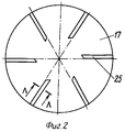
На фиг.2 приведен один вариант осуществления нижней поверхности дискового элемента 17. Figure 2 shows one embodiment of the lower surface of the
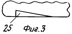
На фиг.3 показано сечение дискового элемента 17, показанного на фиг.2. Figure 3 shows a cross section of the
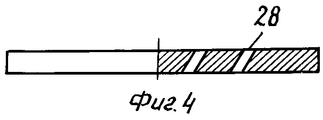
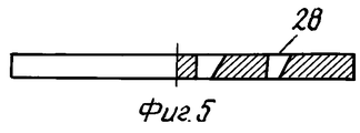
На фиг.4 и 5 показаны два другие варианта осуществления дискового элемента. Figures 4 and 5 show two other embodiments of a disk element.
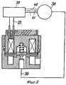
На фиг.6 показан двигатель внутреннего сгорания с иглой форсунки согласно данному изобретению. 6 shows an internal combustion engine with a nozzle needle according to this invention.
Детальное описание изобретения
Ниже приведено описание изобретения через конкретные варианты его осуществления.DETAILED DESCRIPTION OF THE INVENTION
The following is a description of the invention through specific options for its implementation.
На фиг. 1 показано сечение электромагнитного клапана для газообразных текучих сред согласно данному изобретению. Этот конкретный вариант осуществления клапана может быть использован в качестве электромагнитной иглы форсунки для газообразных видов топлива в двигателе внутреннего сгорания. Благодаря своим характеристикам он может, в данном конкретном случае, быть отрегулирован таким образом, чтобы обеспечивать непрямое пульсирующее впрыскивание газообразных видов топлива в двигатель под давлением. Непрямое впрыскивание означает режим впрыска, при котором газообразное топливо добавляется в поток воздуха, подаваемого в цилиндр или цилиндры. Клапан может быть установлен очень близко к впускному отверстию двигателя для создания очень короткого общего времени отклика топливной системы. В многоцилиндровом двигателе для всех цилиндров может быть использован общий клапан с распределением воздушно-газовой смеси через коллектор для каждого соответствующего впускного отверстия. В другой конфигурации для каждого цилиндра может быть установлен отдельный клапан, расположенный в коллекторе вблизи соответствующего входного отверстия. Это дает преимущество отдельного дозирования топлива соответственно в каждый цилиндр. In FIG. 1 shows a cross-section of a solenoid valve for gaseous fluids according to this invention. This particular embodiment of the valve can be used as the electromagnetic needle of a nozzle for gaseous fuels in an internal combustion engine. Due to its characteristics, it can, in this particular case, be adjusted in such a way as to provide an indirect pulsating injection of gaseous fuels into the engine under pressure. Indirect injection means an injection mode in which gaseous fuel is added to a stream of air supplied to a cylinder or cylinders. The valve can be installed very close to the engine inlet to create a very short overall fuel system response time. In a multi-cylinder engine, a common valve can be used for all cylinders with the distribution of the air-gas mixture through the manifold for each corresponding inlet. In another configuration, a separate valve can be installed for each cylinder located in the manifold near the corresponding inlet. This gives the advantage of a separate metering of fuel, respectively, in each cylinder.
Электромагнитный клапан, целиком обозначенный 10, включает магнитную цепь, имеющую закрепленный корпус 12 и дисковый элемент 17, составляющий движущуюся часть указанной магнитной цепи. Следует отметить, что только часть дискового элемента должна быть способна проводить магнитное поле. Соленоид 13 расположен в кольцевом пазе закрепленного корпуса 12. Электрические соединения 33 на соленоиде смонтированы таким образом, чтобы принимать электрический сигнал, что позволяет приводить в действие электромагнитный клапан путем генерирования магнитной силы, которая переместит дисковый элемент 17. The solenoid valve, whole designation 10, includes a magnetic circuit having a fixed housing 12 and a
Кольцевое седло клапана 24, смонтировано таким образом, чтобы взаимодействовать с дисковым элементом; упругий элемент 15, например в форме пружины, в данном варианте осуществления смещает дисковый элемент таким образом, чтобы он находился в контакте с седлом клапана 24, когда клапан не приведен в действие. Таким образом, в нормальном положении клапан закрыт. Естественно, что для общего применения клапан такого типа может быть сконструирован таким образом, чтобы в нормальном положении быть открытым. The annular seat of the valve 24 is mounted so as to interact with the disk element; the elastic element 15, for example in the form of a spring, in this embodiment biases the disk element so that it is in contact with the seat of the valve 24 when the valve is not actuated. Thus, in the normal position, the valve is closed. Naturally, for general use, a valve of this type can be designed to be open in the normal position.
В проиллюстрированном варианте осуществления изобретения дисковый элемент 17 является круглым и для того, чтобы направлять движение дискового элемента в направлении, перпендикулярном поверхности диска, снабжен прикрепленным к нему концентрическим цилиндрическим направляющим элементом или стержнем 34, который расположен перпендикулярно верхней поверхности дискового элемента. In the illustrated embodiment, the
Направляющий элемент 34 дискового элемента 17 в данном варианте осуществления изобретения размещается в подшипнике скольжения 14 в центре закрепленного корпуса 12. Подшипник может быть самосмазывающегося типа. The guide member 34 of the
В данном случае упругий элемент 15 расположен между направляющим элементом и закрепленным корпусом. В варианте осуществления, проиллюстрированном на фиг.1, направляющий элемент 34 представляет собой трубу, цилиндрическая внутренняя часть 35 которой устроена таким образом, чтобы она вмещала нижнюю часть упругого элемента 15, выполненного в виде пружины. Верхняя часть пружины 15 расположена в цилиндрической полости 37 в центре корпуса 12. Цилиндрическая внешняя поверхность направляющего элемента скользит в подшипнике 14 и направляет движение дискового элемента 17. In this case, the elastic element 15 is located between the guide element and the fixed body. In the embodiment illustrated in FIG. 1, the guide member 34 is a pipe, the cylindrical inner part 35 of which is arranged so that it accommodates the lower part of the elastic element 15, made in the form of a spring. The upper part of the spring 15 is located in the cylindrical cavity 37 in the center of the housing 12. The cylindrical outer surface of the guide element slides in the bearing 14 and directs the movement of the
В других вариантах осуществления клапана согласно данному изобретению регулировка направления движения дискового элемента может быть осуществлена по краю диска. В этом случае нет необходимости в центральном направляющем элементе 34 и связанном с ним подшипнике скольжения 14. Естественно, что упругий элемент 15 может быть расположен по краю дискового элемента, и он не обязательно должен иметь форму пружины. Например, он может быть выполнен в виде кольца из эластичного материала. In other embodiments, the implementation of the valve according to this invention, the adjustment of the direction of movement of the disk element can be carried out along the edge of the disk. In this case, there is no need for a central guide member 34 and a sliding bearing 14 associated therewith. Naturally, the resilient member 15 can be positioned along the edge of the disc member, and it does not need to have a spring shape. For example, it can be made in the form of a ring of elastic material.
Для сохранения короткого времени отклика клапана важно, чтобы давление по обе стороны диска всегда было одинаковым, в том числе также и при впуске, когда находящийся под повышенным давлением газ внезапно поступает во впускное отверстие 26 клапана. Этого можно достичь, например, с помощью байпаса в корпусе клапана, что позволяет обеим сторонам диска взаимодействовать пневматически. Подходящие отверстия в диске могут дать тот же результат. Можно также дать возможность газу циркулировать вокруг края диска между диском и внутренней поверхностью корпуса клапана. Для того, чтобы быстро уравнять давление по обе стороны дискового элемента наверху дискового элемента 17 может быть установлен тонкий диск, снабженный по крайней мере одной радиальной прорезью, начинающейся от края диска. To maintain a short valve response time, it is important that the pressure on both sides of the disk is always the same, including during the inlet, when the gas under increased pressure suddenly enters the valve inlet 26. This can be achieved, for example, bypassing the valve body, which allows both sides of the disc to interact pneumatically. Suitable holes in the disc may give the same result. You can also allow gas to circulate around the edge of the disk between the disk and the inner surface of the valve body. In order to quickly equalize the pressure on both sides of the disk element, a thin disk can be installed at the top of the
В конкретном варианте осуществления клапана для использования в качестве иглы форсунки согласно данному изобретению, проиллюстрированном на фиг.1-3, дисковый элемент перемещается только на 0,3 мм, что означает, что турбулентность газа вокруг его края играет пренебрежимо малую роль. In a particular embodiment of the valve for use as the needle of the nozzle of the present invention illustrated in FIGS. 1-3, the disk element moves only 0.3 mm, which means that gas turbulence around its edge plays a negligible role.
Диск 17 может также иметь диаметр, существенно меньше, чем показано на фиг.1, и по краю может быть снабжен лопастями вертушки. The
В проиллюстрированном варианте осуществления активация электромагнитной цепи вызовет движение вверх дискового элемента (см. фиг.1) и, таким образом, клапан откроется. In the illustrated embodiment, the activation of the electromagnetic circuit will cause the upward movement of the disk element (see FIG. 1) and thus the valve will open.
Впускное отверстие 26 для топлива, представляющего собой газообразный поток, расположено на боковой стенке корпуса 18 иглы форсунки. Естественно, что впускное отверстие может быть расположено иначе. The fuel inlet port 26, which is a gaseous stream, is located on the side wall of the nozzle needle housing 18. Naturally, the inlet may be located differently.
В состоянии покоя кольцеобразное седло клапана 24 герметично изолировано от нижней поверхности дискового элемента 17. Предпочтительно кольцо 21, выполненное из, например, какого-нибудь эластичного материала, такого как полимер, образует опорную поверхность (седло). Это позволяет, с одной стороны, поглотить энергию удара, когда диск опускается на седло в результате прекращения работы соленоида 13, и, с другой стороны, это позволяет прекрасно герметично изолировать клапан, так что при закрытом клапане газообразная текучая среда не может поступать от впускного отверстия 26 через клапан в выпускное отверстие 36. At rest, the annular seat of the valve 24 is hermetically isolated from the bottom surface of the
Когда соленоид 13 приведен в действие электрическим сигналом, дисковый элемент 17, по крайней мере часть которого включена в электромагнитную цепь, движется от нижнего положения по направлению к верхнему положению (см. фиг. 1), что дает возможность потоку газообразной среды поступать от впускного отверстия 26 через коаксиальную кольцевую полость 27, расположенную под диском, и проходить дальше между диском и кольцевым седлом в направлении расположенного дальше отверстия 23 и выпускного отверстия 36. Площадь поперечного сечения отверстия 23 клапана в этом варианте осуществления изобретения точно задана для того, чтобы создать звуковой поток газообразной среды через клапан. Это означает, что скорость потока не будет зависеть от давления на выпускной стороне клапана, что очень важно при использовании клапана в качестве иглы форсунки, так как это давление существенно изменяется в ходе рабочего цикла двигателя. В то же время, когда клапан находится в полностью открытом положении, зазор между седлом клапана 24 и диском задан таким образом, чтобы он был много больше площади отверстия 23, что позволяет создать звуковое течение в отверстии 23. Таким образом, поток газообразной текучей среды зависит только от ее давления на впускном отверстии клапана 10. When the solenoid 13 is driven by an electric signal, the
В предпочтительном варианте осуществления изобретения дисковый элемент 17 снабжен выемками 25, расположенными радиально на его нижней поверхности, как показано на фиг. 2. Эти выемки имеют скошенное сечение, что вызывает вращение диска 17, когда газообразная текучая среда проходит от впускного отверстия 26 через клапан по направлению к выпускному отверстию 36. Ступенчатое вращение диска 17 создает предпосылки для равномерного износа седла клапана 24, диска 17 в той области, где он соприкасается с седлом клапана 24 в закрытом состоянии, направляющего элемента 34 диска 17 и подшипника скольжения 14. In a preferred embodiment, the
Вращение диска также может быть обеспечено за счет, например, сквозных отверстий, имеющих боковые стенки, расположенных под углом к нижней и верхней поверхностям диска 17 или за счет расположенных радиально прорезей 28 в диске 17, также имеющих скошенное сечение. The rotation of the disk can also be ensured by, for example, through holes having side walls located at an angle to the lower and upper surfaces of the
За пределами центральной поверхности диска, которая взаимодействует с седлом клапана, материал диска можно удалить для уменьшения массы диска 17. Outside the central surface of the disk, which interacts with the valve seat, the disk material can be removed to reduce the mass of the
В тех случаях, когда клапан используется в качестве иглы форсунки для двигателя внутреннего сгорания 38, электрические соединения 33 соленоида 13 могут быть соединены с блоком управления 39, подающим управляющий сигнал для активации клапана. Предпочтительно, на двигателе установлен ряд зондов 40, 41, ..., измеряющих важные контрольные параметры, которые поступают на блок управления, где осуществляется вычисление согласно соответствующему алгоритму контроля и генерируется результирующий управляющий сигнал. Такое устройство позволяет проводить впрыск газообразного топлива регулируемой продолжительности и с регулируемой частотой, и поэтому, регулируемого объема и с регулируемой фазой. Поэтому игла форсунки может подать топливо в любой конкретный момент цикла работы двигателя, даже когда соответствующий впускной клапан(ы) двигателя закрыт(ы). В этом случае подходящая воздушно-газовая смесь мгновенно запасается в коллекторе в ожидании следующего открытия соответствующего клапана. In cases where the valve is used as the nozzle needle for the
Claims (11)
Applications Claiming Priority (2)
| Application Number | Priority Date | Filing Date | Title |
|---|---|---|---|
| SE9801588A SE9801588D0 (en) | 1998-05-05 | 1998-05-05 | Electromagnetic valve for gaseous fluids |
| SE9801588-6 | 1998-05-05 |
Publications (2)
| Publication Number | Publication Date |
|---|---|
| RU2000130707A RU2000130707A (en) | 2002-11-20 |
| RU2218503C2 true RU2218503C2 (en) | 2003-12-10 |
Family
ID=20411210
Family Applications (1)
| Application Number | Title | Priority Date | Filing Date |
|---|---|---|---|
| RU2000130707/06A RU2218503C2 (en) | 1998-05-05 | 1999-05-05 | Electromagnetic valve for gaseous fluid media |
Country Status (13)
| Country | Link |
|---|---|
| US (1) | US6505112B1 (en) |
| EP (1) | EP1075615B1 (en) |
| JP (1) | JP4351390B2 (en) |
| CN (1) | CN1188617C (en) |
| AT (1) | ATE279673T1 (en) |
| AU (1) | AU769334B2 (en) |
| BR (1) | BR9910247A (en) |
| CA (1) | CA2331171C (en) |
| DE (1) | DE69921116T2 (en) |
| PL (1) | PL189546B1 (en) |
| RU (1) | RU2218503C2 (en) |
| SE (1) | SE9801588D0 (en) |
| WO (1) | WO1999057465A2 (en) |
Cited By (2)
| Publication number | Priority date | Publication date | Assignee | Title |
|---|---|---|---|---|
| RU2592637C2 (en) * | 2010-06-28 | 2016-07-27 | Роберт Бош Гмбх | Minimising chatter armature electromagnetic valve at closing thereof by inhibition of link in residual air gap |
| RU2638496C2 (en) * | 2013-04-19 | 2017-12-13 | ФОРД ГЛОУБАЛ ТЕКНОЛОДЖИЗ, ЭлЭлСи | Method of engine control when emptying gas fuel tank (versions) |
Families Citing this family (11)
| Publication number | Priority date | Publication date | Assignee | Title |
|---|---|---|---|---|
| US7509948B1 (en) | 2007-10-01 | 2009-03-31 | Caterpillar Inc. | Variable displacement pump with an anti-stiction device |
| US9109715B2 (en) * | 2008-10-05 | 2015-08-18 | Alameda Applied Sciences Corp. | Resonant supersonic gas valve and nozzle |
| AT509737B1 (en) | 2010-04-29 | 2015-11-15 | Hoerbiger Kompressortech Hold | GAS VALVE |
| CN102635465B (en) * | 2012-04-16 | 2013-11-06 | 山东汉菱电气有限公司 | Disc type gas snuffle valve |
| CN102661427A (en) * | 2012-05-12 | 2012-09-12 | 中国兵器工业集团第七0研究所 | Direct-driving vibration-resistant electromagnetic valve |
| DE102013100440A1 (en) | 2013-01-16 | 2014-07-17 | Kendrion (Villingen) Gmbh | High pressure valve |
| DE102013212191A1 (en) * | 2013-06-26 | 2014-12-31 | Robert Bosch Gmbh | Method and device for injecting a gaseous medium |
| DE102013212681A1 (en) * | 2013-06-28 | 2014-12-31 | Robert Bosch Gmbh | Solenoid valve and method of manufacturing solenoid valves |
| EP3018392B1 (en) * | 2014-11-05 | 2017-01-04 | FESTO AG & Co. KG | Electromagnetic valve drive, method for producing the same, and solenoid valve equipped with the same |
| CN105864487A (en) * | 2015-12-15 | 2016-08-17 | 长春航空液压控制有限公司 | Disc type electromagnetic attraction structure |
| CN108591578A (en) * | 2018-01-23 | 2018-09-28 | 谭凯诺 | A kind of preceding moving iron core end face actuation high-speed electromagnetic valve |
Citations (3)
| Publication number | Priority date | Publication date | Assignee | Title |
|---|---|---|---|---|
| US2631612A (en) * | 1949-06-25 | 1953-03-17 | Gen Controls Co | High-pressure valve |
| US4759528A (en) * | 1987-11-16 | 1988-07-26 | Rockwell International Corporation | Valve actuator |
| US4883252A (en) * | 1989-01-23 | 1989-11-28 | Colt Industries Inc. | Electromagnet and valve assembly |
Family Cites Families (19)
| Publication number | Priority date | Publication date | Assignee | Title |
|---|---|---|---|---|
| US2922614A (en) * | 1956-06-18 | 1960-01-26 | Honeywell Regulator Co | Hum-free solenoid device |
| US2910249A (en) * | 1958-03-19 | 1959-10-27 | Bendix Aviat Corp | Solenoid actuated valve for controlling flow to a nozzle |
| JPS46617Y1 (en) * | 1966-08-10 | 1971-01-11 | ||
| JPS5086730U (en) * | 1973-12-12 | 1975-07-23 | ||
| JPS60162779U (en) * | 1984-04-06 | 1985-10-29 | ジエコ−株式会社 | solenoid valve |
| US4655396A (en) * | 1985-09-25 | 1987-04-07 | United Technologies Diesel Systems, Inc. | Electromagnetic fuel injector |
| JPS62118174A (en) * | 1985-11-19 | 1987-05-29 | Mitsubishi Electric Corp | Flow control valve device |
| JPH0338540Y2 (en) * | 1987-03-30 | 1991-08-14 | ||
| US4925155A (en) * | 1988-07-14 | 1990-05-15 | Crane Electronics, Inc. | Control valve and method of controlling material flow through a conduit |
| US4958774A (en) * | 1989-06-21 | 1990-09-25 | General Motors Corporation | Fuel injection |
| EP0420599B1 (en) * | 1989-09-29 | 1995-06-21 | Ortech Corporation | Flow control system |
| US5086980A (en) * | 1990-10-09 | 1992-02-11 | Ford Motor Company | Fuel injector for an internal combustion engine |
| JP2518031Y2 (en) * | 1990-12-19 | 1996-11-20 | 株式会社ユニシアジェックス | Fuel injection valve |
| GB9217281D0 (en) * | 1992-08-14 | 1992-09-30 | Lucas Ind Plc | Fuel injector |
| US5348233A (en) * | 1993-03-01 | 1994-09-20 | General Motors Corporation | High volume gaseous fuel injector |
| JP2837112B2 (en) * | 1995-06-09 | 1998-12-14 | 株式会社平井 | Mass flow control method and apparatus using sonic nozzle |
| JP3291161B2 (en) * | 1995-06-12 | 2002-06-10 | 株式会社フジキン | Pressure type flow controller |
| JP3580645B2 (en) * | 1996-08-12 | 2004-10-27 | 忠弘 大見 | Pressure type flow controller |
| US6161783A (en) * | 1999-09-17 | 2000-12-19 | Impco Technologies, Inc. | Gaseous fuel injector |
-
1998
- 1998-05-05 SE SE9801588A patent/SE9801588D0/en unknown
-
1999
- 1999-05-05 CN CNB998057878A patent/CN1188617C/en not_active Expired - Fee Related
- 1999-05-05 AU AU41391/99A patent/AU769334B2/en not_active Ceased
- 1999-05-05 AT AT99924888T patent/ATE279673T1/en not_active IP Right Cessation
- 1999-05-05 US US09/674,429 patent/US6505112B1/en not_active Expired - Lifetime
- 1999-05-05 WO PCT/EP1999/003102 patent/WO1999057465A2/en not_active Ceased
- 1999-05-05 CA CA002331171A patent/CA2331171C/en not_active Expired - Fee Related
- 1999-05-05 DE DE69921116T patent/DE69921116T2/en not_active Expired - Lifetime
- 1999-05-05 PL PL99344527A patent/PL189546B1/en unknown
- 1999-05-05 EP EP99924888A patent/EP1075615B1/en not_active Expired - Lifetime
- 1999-05-05 BR BR9910247-1A patent/BR9910247A/en not_active IP Right Cessation
- 1999-05-05 RU RU2000130707/06A patent/RU2218503C2/en not_active IP Right Cessation
- 1999-05-05 JP JP2000547389A patent/JP4351390B2/en not_active Expired - Fee Related
Patent Citations (3)
| Publication number | Priority date | Publication date | Assignee | Title |
|---|---|---|---|---|
| US2631612A (en) * | 1949-06-25 | 1953-03-17 | Gen Controls Co | High-pressure valve |
| US4759528A (en) * | 1987-11-16 | 1988-07-26 | Rockwell International Corporation | Valve actuator |
| US4883252A (en) * | 1989-01-23 | 1989-11-28 | Colt Industries Inc. | Electromagnet and valve assembly |
Cited By (2)
| Publication number | Priority date | Publication date | Assignee | Title |
|---|---|---|---|---|
| RU2592637C2 (en) * | 2010-06-28 | 2016-07-27 | Роберт Бош Гмбх | Minimising chatter armature electromagnetic valve at closing thereof by inhibition of link in residual air gap |
| RU2638496C2 (en) * | 2013-04-19 | 2017-12-13 | ФОРД ГЛОУБАЛ ТЕКНОЛОДЖИЗ, ЭлЭлСи | Method of engine control when emptying gas fuel tank (versions) |
Also Published As
| Publication number | Publication date |
|---|---|
| CN1188617C (en) | 2005-02-09 |
| EP1075615A2 (en) | 2001-02-14 |
| HK1037395A1 (en) | 2002-02-08 |
| JP2002513899A (en) | 2002-05-14 |
| WO1999057465A2 (en) | 1999-11-11 |
| CA2331171A1 (en) | 1999-11-11 |
| AU769334B2 (en) | 2004-01-22 |
| BR9910247A (en) | 2001-01-30 |
| WO1999057465A3 (en) | 2000-01-06 |
| EP1075615B1 (en) | 2004-10-13 |
| PL189546B1 (en) | 2005-08-31 |
| US6505112B1 (en) | 2003-01-07 |
| CA2331171C (en) | 2007-08-21 |
| DE69921116T2 (en) | 2005-11-17 |
| PL344527A1 (en) | 2001-11-05 |
| SE9801588D0 (en) | 1998-05-05 |
| AU4139199A (en) | 1999-11-23 |
| DE69921116D1 (en) | 2004-11-18 |
| ATE279673T1 (en) | 2004-10-15 |
| CN1299450A (en) | 2001-06-13 |
| JP4351390B2 (en) | 2009-10-28 |
Similar Documents
| Publication | Publication Date | Title |
|---|---|---|
| RU2218503C2 (en) | Electromagnetic valve for gaseous fluid media | |
| US5018501A (en) | Electromagnetic fuel injection valve apparatus | |
| JP2001525034A (en) | Valve device | |
| RU2000130707A (en) | ELECTROMAGNETIC VALVE FOR GAS-FREE FLUID MEDIA | |
| JPH0223753B2 (en) | ||
| CA1134691A (en) | Fuel injection apparatus and system | |
| US7284542B2 (en) | Tapered toroidal flow control valve and fuel metering device | |
| KR100362546B1 (en) | Fuel supplying device for engine | |
| US4997458A (en) | Tilt valve carburetor for gaseous fuel systems | |
| US4064693A (en) | Secondary air supply system for internal combustion engines | |
| KR100519879B1 (en) | Gas valve | |
| KR20000076220A (en) | Gate-valve system | |
| EP1336747A2 (en) | Electrical injector for gaseous fuel | |
| KR102794910B1 (en) | Exhaust housing for an internal combustion engine and method of guiding exhaust gas of the internal combustion engine | |
| KR100612055B1 (en) | Systems for intermittent and / or continuous introduction of gaseous fuels | |
| KR830006576A (en) | Diesel / gas engine | |
| SU736883A3 (en) | Fuel flow control device of carburetor dosing system | |
| DE69839608D1 (en) | INJECTION VALVE FOR FUEL MUFFS | |
| HK1037395B (en) | Electromagnetic valve for gaseous fluids | |
| RU2065200C1 (en) | Gaseous fuel pressure regulator for internal combustion engine | |
| EP1887210A2 (en) | A device for gas metering, especially for an internal combustion engine | |
| JPH0561462B2 (en) | ||
| JP4276383B2 (en) | Compressed natural gas injector tolerant pollutants and method of directing gaseous fuel by injector | |
| JP2020041507A (en) | Evaporated fuel treatment device | |
| RU2052148C1 (en) | Starting unit for fuel supply system of gas internal combustion engine |
Legal Events
| Date | Code | Title | Description |
|---|---|---|---|
| MM4A | The patent is invalid due to non-payment of fees |
Effective date: 20180506 |