RU2216632C2 - Method of operation of well producing oil and gas and activated by pumping system (versions) - Google Patents
Method of operation of well producing oil and gas and activated by pumping system (versions) Download PDFInfo
- Publication number
- RU2216632C2 RU2216632C2 RU99102971/06A RU99102971A RU2216632C2 RU 2216632 C2 RU2216632 C2 RU 2216632C2 RU 99102971/06 A RU99102971/06 A RU 99102971/06A RU 99102971 A RU99102971 A RU 99102971A RU 2216632 C2 RU2216632 C2 RU 2216632C2
- Authority
- RU
- Russia
- Prior art keywords
- electric motor
- pump
- speed
- well
- vmin
- Prior art date
Links
- 238000000034 method Methods 0.000 title claims abstract description 36
- 238000005086 pumping Methods 0.000 title abstract description 7
- 238000004519 manufacturing process Methods 0.000 claims abstract description 13
- 238000013461 design Methods 0.000 claims description 25
- 230000001681 protective effect Effects 0.000 claims description 7
- 230000002829 reductive effect Effects 0.000 claims description 7
- 238000001514 detection method Methods 0.000 claims description 3
- 230000006641 stabilisation Effects 0.000 claims description 3
- 238000011105 stabilization Methods 0.000 claims description 3
- 241000963790 Beilschmiedia tawa Species 0.000 claims 1
- 238000013022 venting Methods 0.000 claims 1
- 229930195733 hydrocarbon Natural products 0.000 abstract description 21
- 150000002430 hydrocarbons Chemical class 0.000 abstract description 21
- 230000000694 effects Effects 0.000 abstract description 4
- 239000000126 substance Substances 0.000 abstract 1
- 239000004215 Carbon black (E152) Substances 0.000 description 7
- 238000001816 cooling Methods 0.000 description 5
- 238000013021 overheating Methods 0.000 description 4
- 230000015556 catabolic process Effects 0.000 description 3
- 230000001105 regulatory effect Effects 0.000 description 3
- 230000035939 shock Effects 0.000 description 2
- 230000002159 abnormal effect Effects 0.000 description 1
- 230000004888 barrier function Effects 0.000 description 1
- 230000008901 benefit Effects 0.000 description 1
- 239000011230 binding agent Substances 0.000 description 1
- 230000033228 biological regulation Effects 0.000 description 1
- 230000008859 change Effects 0.000 description 1
- 230000001276 controlling effect Effects 0.000 description 1
- 238000009472 formulation Methods 0.000 description 1
- 230000006870 function Effects 0.000 description 1
- 238000010438 heat treatment Methods 0.000 description 1
- 230000000670 limiting effect Effects 0.000 description 1
- 239000000203 mixture Substances 0.000 description 1
- 210000002445 nipple Anatomy 0.000 description 1
- 239000003129 oil well Substances 0.000 description 1
- 238000011017 operating method Methods 0.000 description 1
- 238000002360 preparation method Methods 0.000 description 1
- 238000004321 preservation Methods 0.000 description 1
- 230000002035 prolonged effect Effects 0.000 description 1
- 230000009467 reduction Effects 0.000 description 1
- 238000007670 refining Methods 0.000 description 1
- 230000008439 repair process Effects 0.000 description 1
- 230000002441 reversible effect Effects 0.000 description 1
- 230000002226 simultaneous effect Effects 0.000 description 1
- 230000003068 static effect Effects 0.000 description 1
- 210000004243 sweat Anatomy 0.000 description 1
- 238000012360 testing method Methods 0.000 description 1
- 230000007704 transition Effects 0.000 description 1
Images
Classifications
-
- E—FIXED CONSTRUCTIONS
- E21—EARTH OR ROCK DRILLING; MINING
- E21B—EARTH OR ROCK DRILLING; OBTAINING OIL, GAS, WATER, SOLUBLE OR MELTABLE MATERIALS OR A SLURRY OF MINERALS FROM WELLS
- E21B34/00—Valve arrangements for boreholes or wells
- E21B34/16—Control means therefor being outside the borehole
-
- E—FIXED CONSTRUCTIONS
- E21—EARTH OR ROCK DRILLING; MINING
- E21B—EARTH OR ROCK DRILLING; OBTAINING OIL, GAS, WATER, SOLUBLE OR MELTABLE MATERIALS OR A SLURRY OF MINERALS FROM WELLS
- E21B43/00—Methods or apparatus for obtaining oil, gas, water, soluble or meltable materials or a slurry of minerals from wells
- E21B43/12—Methods or apparatus for controlling the flow of the obtained fluid to or in wells
- E21B43/121—Lifting well fluids
- E21B43/128—Adaptation of pump systems with down-hole electric drives
Landscapes
- Geology (AREA)
- Life Sciences & Earth Sciences (AREA)
- Engineering & Computer Science (AREA)
- Mining & Mineral Resources (AREA)
- Environmental & Geological Engineering (AREA)
- Fluid Mechanics (AREA)
- Physics & Mathematics (AREA)
- General Life Sciences & Earth Sciences (AREA)
- Geochemistry & Mineralogy (AREA)
- Control Of Positive-Displacement Pumps (AREA)
- Lubrication Of Internal Combustion Engines (AREA)
- Jet Pumps And Other Pumps (AREA)
- Separation By Low-Temperature Treatments (AREA)
Abstract
Description
Настоящее изобретение касается способа эксплуатации скважины, осуществляющей добычу нефти и газа, активированную системой подкачки, расположенной на дне скважины. The present invention relates to a method for operating a well producing oil and gas activated by a booster system located at the bottom of the well.
В некоторых нефтяных скважинах дебит углеводородов в виде нефти и газа невелик из-за низкого давления в нефтяном коллекторе. In some oil wells, the production rate of hydrocarbons in the form of oil and gas is low due to the low pressure in the oil reservoir.
Для повышения дебита углеводородов применяют классический способ, известный под названием "способ погружного электронасоса". To increase the flow rate of hydrocarbons, the classical method known as the "submersible electric pump method" is used.
Согласно этому способу, систему подкачки, состоящую из насоса, приводимого в действие электродвигателем, помещают на дно скважины таким образом, чтобы она засасывала нефть из углеводородного коллектора и выбрасывала ее в выкидную колонну скважины, соединяющую дно скважины, расположенное на уровне коллектора, с устьем скважины, расположенным в ее верхней части. According to this method, the pumping system, consisting of a pump driven by an electric motor, is placed on the bottom of the well so that it draws oil from the hydrocarbon reservoir and throws it into the flow column connecting the bottom of the well, located at the level of the collector, with the wellhead located at its top.
Электропитание двигателя обычно обеспечивается частотным вариатором, позволяющим менять скорость вращения насоса. Motor power is usually provided by a frequency variator, allowing you to change the speed of rotation of the pump.
Выкидная колонна скважины вместе с обсадной колонной, образующей стенки скважины, образуют кольцевое пространство, позволяющее выводить избыточный свободный газ в термодинамических условиях, существующих на дне скважины. The flow casing of the well, together with the casing, forming the walls of the borehole, form an annular space, allowing to remove excess free gas in thermodynamic conditions existing at the bottom of the borehole.
В верхней части скважины выкидная колонна связана с магистралью, оборудованной штуцером с переменным сечением на выводе нефти, а кольцевое пространство переходит в другую магистраль, оборудованную штуцером с переменным сечением для вывода газа. Эти два штуцера позволяют регулировать дебит нефти и газа. In the upper part of the well, the flow string is connected to a line equipped with a nozzle with a variable cross-section at the oil outlet, and the annular space passes to another line equipped with a nozzle with a variable cross-section for gas outlet. These two fittings allow you to adjust the flow rate of oil and gas.
Способ эксплуатации одной из таких установок, описанный в патенте США 5 634 522, состоит в ограничении измеряемого уровня, до которого поднимается нефть в кольцевом пространстве, заранее определенным значением путем воздействия на отверстие нефтевыводного штуцера. The method of operating one of these units, described in US Pat. No. 5,634,522, consists in limiting the measured level to which oil rises in the annular space by a predetermined value by exposing the outlet of the oil outlet fitting.
Практикуется также повышение скорости работы двигателя пропорционально времени его работы в период начального пуска добычи продукта и в период повторного пуска после остановки работы скважины. It is also practiced to increase the speed of the engine in proportion to the time of its operation during the initial start-up of production of the product and in the period of restarting after stopping the well.
Защиту электродвигателя от перегрева обычно осуществляют с помощью прерывателя, который отключает электропитание в тот момент, когда потребляемый ток превышает установленный верхний порог. Protection of the electric motor from overheating is usually carried out using a circuit breaker that turns off the power at the moment when the current consumption exceeds the set upper threshold.
Однако эта защита не является эффективной при всех условиях эксплуатации скважины. Например, при низком дебите нефти нагрев вследствие эффекта Джоуля снижается, но охлаждение циркулирующим в двигателе маслом при этом также мало. В этих условиях сочетание этих двух противоположных эффектов может привести к чрезмерному повышению температуры двигателя при бездействии защиты, поскольку при этом верхний порог потребляемого тока не превышается. Подобные подъемы температуры имеют следствием уменьшение срока службы двигателя и в конечном итоге его поломку. However, this protection is not effective under all operating conditions of the well. For example, with a low oil flow rate, heating due to the Joule effect is reduced, but the cooling by the oil circulating in the engine is also small. Under these conditions, the combination of these two opposite effects can lead to an excessive increase in the temperature of the motor when the protection is inactive, since the upper threshold of the current consumption is not exceeded. Such temperature rises result in a reduction in the life of the engine and ultimately its breakdown.
Другие термодинамические, тепловые и гидравлические явления могут приводить к временному избытку свободного газа в насосе. Этот избыток газа в некоторых случаях может приводить к неустойчивой работе или к недостаточному охлаждению. Все эти явления, влияющие на срок службы двигателя насоса, не принимаются во внимание в существующих способах эксплуатации. Other thermodynamic, thermal, and hydraulic phenomena can lead to a temporary excess of free gas in the pump. This excess gas in some cases can lead to unstable operation or to insufficient cooling. All of these phenomena affecting the life of the pump motor are not taken into account in existing operating methods.
Еще одним недостатком существующих способов является то, что любое отклонение от рабочего режима приводит к остановке работы и к дорогостоящему повторному пуску. Another disadvantage of the existing methods is that any deviation from the operating mode leads to a shutdown and costly restart.
Техническим результатом настоящего изобретения является создание способа эксплуатации скважины, осуществляющей добычу нефти и газа, активированную системой подкачки с помощью погружного электронасоса, в котором улучшена защита насоса и его приводного электродвигателя при всех рабочих условиях, в результате чего уменьшаются последствия тепловых и гидравлических ударов и обеспечивается взаимозависимость регулирования питания электродвигателя и регулирования вывода продуктов из скважины для сведения к минимуму остановок ее работы, увеличен срок службы системы подкачки и существенно уменьшено количество дорогостоящих вмешательств в работу скважины для проведения ремонтных работ и связанных с этим повторных пусков. The technical result of the present invention is to provide a method of operating a well producing oil and gas, activated by a pumping system using a submersible electric pump, in which the protection of the pump and its drive motor is improved under all operating conditions, thereby reducing the effects of thermal and hydraulic shocks and ensuring interdependence regulating the power of the electric motor and regulating the output of products from the well to minimize shutdowns, the life of the pumping system has been increased and the number of costly interventions in the well’s work for repair work and related restarting has been significantly reduced.
Этот технический результат достигается тем, что способ эксплуатации скважины, осуществляющей добычу нефти и газа, активированную системой подкачки, содержащей расположенный на дне скважины погружной насос, приводимый в действие электродвигателем, потребляющим ток известной силы, причем в верхней части скважины имеется нефтевыводной штуцер и газовыводной штуцер, согласно изобретению имеет пусковой период, при подготовительной стадии которого воздействуют на газовыводной штуцер для приведения давления на входе штуцера к заданному пусковому значению давления, воздействуют на нефтевыводной штуцер для приведения давления на входе штуцера к заданному пусковому значению давления, закрывают нефтевыводной штуцер, проверяют не подключен ли электродвигатель к сети и соответствует ли состояние насоса пуску, в стадии вывода скважины в режим добычи продуктов постепенно подводят ток к электродвигателю до вращения насоса с минимальной заданной скоростью, проверяют после определенной выдержки, превышает ли давление на входе нефтевыводного штуцера заданный порог подъема давления, проверяют после определенной выдержки, превышает ли потребляемый электродвигателем ток заданный порог, продолжают вращение насоса при преодолении двух порогов и в противном случае отключают насос, постепенно увеличивают степень открытия нефтевыводного штуцера до заданной величины, выжидают в течение предусмотренного стабилизационного периода, осуществляют контроль надежности работы путем одновременной проверки потребляемого электродвигателем тока и производительности скважины с использованием, по меньшей мере, одного показателя производительности, регулируют давление на входе газовыводного штуцера до заданной пусковой величины. This technical result is achieved in that a method of operating a well producing oil and gas activated by a booster system containing a submersible pump located at the bottom of the well, driven by an electric motor that consumes a current of known force, with an oil outlet fitting and a gas outlet fitting at the top of the well , according to the invention, has a start-up period, during the preparatory stage of which they act on the gas outlet fitting to bring the pressure at the inlet of the fitting to a predetermined point pressure value, act on the oil outlet to bring the pressure at the inlet of the nozzle to a predetermined starting pressure value, close the oil outlet, check whether the electric motor is connected to the network and whether the condition of the pump starts up, in the output stage of the well, the current is gradually applied to the production mode to the electric motor before the pump rotates with a minimum predetermined speed, check after a certain exposure, whether the pressure at the inlet of the oil outlet nipple exceeds a predetermined pressure rise threshold After a certain exposure, they check whether the current consumed by the electric motor exceeds a predetermined threshold, continue to rotate the pump when two thresholds are overcome and otherwise turn off the pump, gradually increase the degree of opening of the oil outlet to a predetermined value, wait for the prescribed stabilization period, monitor the reliability of operation by simultaneously checking the current consumed by the electric motor and the well productivity using at least one display capacity, adjust the pressure at the inlet of the gas outlet fitting to a predetermined starting value.
При установлении соответствия состояния насоса пуску целесообразно проверить то, что насос, являющийся насосом ротационного типа, оборудованным датчиком направления вращения, не вращается в направлении, обратном нормальному направлению вращения, что время между двумя последовательными попытками пуска насоса превосходит заданное время и что после определенного количества попыток пуска, произведенных в течение предусмотренного времени, очередная попытка производится только после заранее определенной выдержки. When establishing the correspondence of the state of the start-up pump, it is advisable to verify that the pump, which is a rotary type pump equipped with a rotation direction sensor, does not rotate in the direction opposite to the normal direction of rotation, that the time between two consecutive attempts to start the pump exceeds a predetermined time and that after a certain number of attempts start-up made within the prescribed time, the next attempt is made only after a predetermined exposure.
Потребляемый двигателем ток можно сопоставить с независимыми один от другого верхним и нижним порогами скорости электродвигателя, и преодоление одного из этих порогов приводит к остановке насоса, а при проверке потребляемого электродвигателем тока для соблюдения надежности его работы дополнительно сопоставляют величину тока с нижним порогом и, когда этот порог преодолевается и время после преодоления этого порога превышает заданную величину, останавливают насос, проверяют после выдержки в течение заданного времени устойчивость потребляемого электродвигателем тока и, когда имеет место неустойчивость и ее продолжительность больше предусмотренного времени, останавливают насос. The current consumed by the motor can be compared with the upper and lower thresholds of the motor speed, independent of one another, and overcoming one of these thresholds will stop the pump, and when checking the current consumed by the motor to maintain its reliability, they additionally compare the current value with the lower threshold and, when this the threshold is overcome and the time after overcoming this threshold exceeds a predetermined value, the pump is stopped, and after holding for a predetermined time, the sweat stability Bang motor current and when instability occurs and its duration longer stipulated time, stopping the pump.
Можно при проверках производительности скважины в качестве показателя производительности принять, по меньшей мере, одну физическую переменную, характеризующую дебит нефти, сравнивают значения этой переменной с заданным пороговым значением, преодоление которого рассматривается как признак эффективной работы, если оно сохраняется в течение заданного времени, и останавливают насос при преодолении названного порога. When checking well productivity, at least one physical variable characterizing the oil flow rate can be taken as a performance indicator, the values of this variable are compared with a given threshold value, overcoming of which is considered as a sign of effective operation, if it remains for a given time, and stopped pump overcoming the named threshold.
Целесообразно в послепусковой период одновременно увеличивать скорость электродвигателя до заданной проектной величины, открывают нефтевыводной штуцер до степени открытия, рассчитанной на основе проектной величины скорости электродвигателя, воздействуют на газовыводной штуцер для поддержания давления на входе этого штуцера на уровне, рассчитанном на основе проектной величины скорости электродвигателя, осуществляют последующий контроль надежности работы путем проверки потребляемого электродвигателем тока и производительности скважины с использованием показателей производительности. It is advisable in the post-launch period to simultaneously increase the speed of the electric motor to a predetermined design value, open the oil outlet fitting to the opening degree calculated on the basis of the design value of the electric motor speed, act on the gas outlet fitting to maintain the pressure at the inlet of this fitting at a level calculated based on the design value of the electric motor speed, carry out subsequent control of reliability by checking the current consumed by the electric motor and performance with Wells using performance indicators.
Можно степень открытия нефтевыводного штуцера рассчитать по следующей формуле:
S(нефт)=α(V-Vmin)+Smin
при Vmin<V<Vmax,
где S(нефт) - степень открытия нефтевыводного штуцера;
V - заданное значение скорости электродвигателя;
α - константа, определяемая по формуле
![]()
Smin, Smax - соответственно степень минимального и максимального открытия нефтевыводного штуцера при минимальной и максимальной скорости электродвигателя;
Vmin и Vmax - соответственно минимальная и максимальная скорости электродвигателя;
α, Smin, Smax, Vmin и Vmax определяются на основе характеристик скважины, насоса и электродвигателя.You can calculate the degree of opening of the oil outlet fitting according to the following formula:
S (oil) = α (V-Vmin) + Smin
for Vmin <V <Vmax,
where S (oil) is the degree of opening of the oil outlet fitting;
V is the set value of the speed of the electric motor;
α is a constant determined by the formula
![]()
Smin, Smax - respectively, the degree of minimum and maximum opening of the oil outlet at the minimum and maximum speed of the electric motor;
Vmin and Vmax are the minimum and maximum speeds of the electric motor, respectively;
α, Smin, Smax, Vmin, and Vmax are determined based on the characteristics of the well, pump, and motor.
Давление на входе газовыводного штуцера можно рассчитать по следующей формуле:
Р(газ)=β(V-Vmin)+Ро
при Vmin<V<Vmax,
где Р(газ) - давление на входе в газовыводной штуцер;
V - проектная величина скорости электродвигателя;
β - константа, определяемая по формуле
![]()
Ро и P1 - значения давления газа на входе газовыводного штуцера, соответствующие минимальной и максимальной скорости электродвигателя;
Vmin и Vmax - соответственно минимальная и максимальная скорости двигателя,
β, Ро, P1, Vmin и Vmax определяются на основе характеристик скважины, насоса и электродвигателя.The pressure at the inlet of the gas outlet fitting can be calculated by the following formula:
P (gas) = β (V-Vmin) + Po
for Vmin <V <Vmax,
where P (gas) is the pressure at the inlet to the gas outlet fitting;
V is the design value of the speed of the electric motor;
β is a constant determined by the formula
![]()
Po and P 1 - gas pressure values at the inlet of the gas outlet fitting, corresponding to the minimum and maximum speed of the electric motor;
Vmin and Vmax are the minimum and maximum engine speeds, respectively
β, Po, P 1 , Vmin and Vmax are determined based on the characteristics of the well, pump and electric motor.
Поскольку потребляемый электродвигателем ток сопоставляется с независимым один от другого верхним и нижним порогами скорости двигателя и преодоление одного из этих порогов приводит к остановке насоса, при проверках потребляемого электродвигателем тока для соблюдения надежности его работы можно дополнительно сопоставить величину тока с верхним и нижним порогами, зависящими от скорости электродвигателя, при преодолении одного из этих порогов снижают скорость, а если порог продолжает при этом оставаться преодоленным, останавливают насос, проверяют устойчивость потребляемого электродвигателем тока и при обнаружении неустойчивости снижают скорость до заданного значения, а если продолжительность неустойчивости превышает предусмотренное время, останавливают насос. Since the current consumed by the electric motor is compared with the upper and lower thresholds of the motor speed that are independent of one another and overcoming one of these thresholds causes the pump to stop, when checking the current consumed by the electric motor to maintain its reliability, it is possible to additionally compare the current value with the upper and lower thresholds, depending on the speed of the electric motor, when one of these thresholds is overcome, the speed is reduced, and if the threshold continues to be overcome, they stop at cs, they check the stability of the current consumed by the electric motor and, if instability is detected, reduce the speed to a predetermined value, and if the duration of the instability exceeds the prescribed time, stop the pump.
Верхний и нижний пороги потребляемого электродвигателем тока, зависящие от скорости электродвигателя, можно рассчитать по следующим формулам:
I(верх)=INmin+γ(V-Vmin)+ΔI
при Vmin<V<Vmax;
I(нижн)=INmin+γ(V-Vmin)-ΔI
при Vmin<V<Vmax,
где I(верх) - верхний порог потребляемого электродвигателем тока,
I(нижн) - нижний порог потребляемого электродвигателем тока,
V - скорость электродвигателя,
INmin и INmax - соответственно минимальное и максимальное значения потребляемого электродвигателем тока при соответственно минимальной и максимальной скорости электродвигателя,
Vmin и Vmax - соответственно минимальная и максимальная скорости электродвигателя, определяемые на основе характеристик скважины, насоса и электродвигателя,
γ и ΔI - - константы, рассчитываемые для каждой скважины на основе характеристик электродвигателя,
![]()
ΔI является допустимым отклонением величины потребляемого электродвигателем тока от его теоретического значения, обеспечивающим нормальную работу скважины.The upper and lower thresholds of the current consumed by the electric motor, depending on the speed of the electric motor, can be calculated by the following formulas:
I (top) = INmin + γ (V-Vmin) + ΔI
for Vmin <V <Vmax;
I (lower) = INmin + γ (V-Vmin) -ΔI
for Vmin <V <Vmax,
where I (top) is the upper threshold of the current consumed by the electric motor,
I (lower) - the lower threshold of the current consumed by the electric motor,
V is the speed of the electric motor,
INmin and INmax are, respectively, the minimum and maximum values of the current consumed by the electric motor at the corresponding minimum and maximum speeds of the electric motor,
Vmin and Vmax are respectively the minimum and maximum speeds of the electric motor, determined on the basis of the characteristics of the well, pump and electric motor,
γ and ΔI - are constants calculated for each well based on the characteristics of the electric motor,
![]()
ΔI is the permissible deviation of the current consumed by the electric motor from its theoretical value, ensuring the normal operation of the well.
При проверке производительности скважины можно принять в качестве показателя производительности, по меньшей мере, одну физическую переменную, характеризующую дебит нефти, и сравнивают значения этой переменной с, по меньшей мере, одним заданным пороговым значением, преодоление которого рассматривается как признак эффективной работы, если оно сохраняется в течение заданного времени, и снижают скорость насоса при преодолении порога. When checking well productivity, at least one physical variable characterizing oil production can be taken as a productivity indicator, and the values of this variable are compared with at least one predetermined threshold value, overcoming of which is considered as a sign of effective work, if it is preserved for a given time, and reduce the speed of the pump when crossing the threshold.
Физическую переменную, характеризующую дебит нефти, можно выбрать из группы переменных, включающих перепад давления, создаваемый при ограничении выхода нефти, дебит свободного газа, давление на глубине скважины на входе насоса, давление на входе нефтевыводного штуцера и температуру на выходе нефти. The physical variable characterizing the oil flow rate can be selected from the group of variables including the pressure drop created when the oil output is limited, free gas flow rate, pressure at the depth of the well at the pump inlet, pressure at the inlet of the oil outlet and oil outlet temperature.
Скважину можно оборудовать защитным устройством, немедленно закрывают нефтевыводной и газовыводной штуцеры и останавливают электродвигатель при включении в действие этого устройства. The well can be equipped with a protective device, immediately close the oil outlet and gas outlet fittings and stop the electric motor when this device is turned on.
Вышеуказанный технический результат достигается также и тем, что в способе эксплуатации скважины, осуществляющей добычу нефти и газа, активированную системой подкачки, содержащей расположенный на дне скважины погружной насос, приводимый в действие электродвигателем, потребляющим ток известной силы, причем в верхней части скважины имеется нефтевыводной штуцер и газовыводной штуцер, согласно изобретению во время послепускового периода увеличивают скорость электродвигателя до заданной проектной величины, открывают нефтевыводной штуцер до степени открытия, рассчитанной на основе проектной величины скорости электродвигателя, воздействуют на газовыводной штуцер для поддержания давления на входе этого штуцера на уровне, рассчитанном на основе проектной величины скорости электродвигателя, осуществляют заключительный контроль надежности работы путем проверки потребляемого электродвигателем тока и производительности скважины с использованием показателей производительности. The above technical result is also achieved by the fact that in the method of operating a well producing oil and gas, activated by a booster system containing a submersible pump located at the bottom of the well, driven by an electric motor consuming a current of known force, and at the top of the well there is an oil outlet fitting and gas outlet, according to the invention during the post-launch period, increase the speed of the electric motor to a predetermined design value, open the oil outlet Up to the opening degree, calculated on the basis of the design value of the electric motor speed, they act on the gas outlet fitting to maintain the pressure at the inlet of this nozzle at a level calculated on the basis of the design value of the electric motor speed, they carry out final control of the reliability by checking the current consumed by the electric motor and the well productivity using performance indicators.
Степень открытия нефтевыводного штуцера можно рассчитать по следующей формуле:
S(нефт)=α(V-Vmin)+Smin
при Vmin<V<Vmax,
где S(нефт) - степень открытия нефтевыводного штуцера;
V - заданное значение скорости электродвигателя;
α - константа, определяемая по формуле
![]()
Smin, Smax - соответственно степень минимального и максимального открытия нефтевыводного штуцера при минимальной и максимальной скорости электродвигателя;
Vmin и Vmax - соответственно минимальная и максимальная скорости электродвигателя;
α, Smin, Smax, Vmin и Vmax определяются на основе характеристик скважины, насоса и электродвигателя.The degree of opening of the oil outlet can be calculated by the following formula:
S (oil) = α (V-Vmin) + Smin
for Vmin <V <Vmax,
where S (oil) is the degree of opening of the oil outlet fitting;
V is the set value of the speed of the electric motor;
α is a constant determined by the formula
![]()
Smin, Smax - respectively, the degree of minimum and maximum opening of the oil outlet at the minimum and maximum speed of the electric motor;
Vmin and Vmax are the minimum and maximum speeds of the electric motor, respectively;
α, Smin, Smax, Vmin, and Vmax are determined based on the characteristics of the well, pump, and motor.
Давление на входе в газовыводной штуцер можно рассчитать по следующей формуле:
Р(газ)=β(V-Vmin)+Ро
при Vmin<V<Vmax,
где Р(газ) - давление на входе в газовыводной штуцер;
V - проектная величина скорости электродвигателя;
β - константа, определяемая по формуле
![]()
Ро и P1 - значения давления газа на входе газовыводного штуцера, соответствующие минимальной и максимальной скорости электродвигателя;
Vmin и Vmax - соответственно минимальная и максимальная скорости двигателя;
β, Ро, Pi, Vmin и Vmax определяются на основе характеристик скважины, насоса и электродвигателя.The pressure at the inlet to the gas outlet fitting can be calculated by the following formula:
P (gas) = β (V-Vmin) + Po
for Vmin <V <Vmax,
where P (gas) is the pressure at the inlet to the gas outlet fitting;
V is the design value of the speed of the electric motor;
β is a constant determined by the formula
![]()
Po and P 1 - gas pressure values at the inlet of the gas outlet fitting, corresponding to the minimum and maximum speed of the electric motor;
Vmin and Vmax are the minimum and maximum engine speeds, respectively;
β, Po, Pi, Vmin, and Vmax are determined based on the characteristics of the well, pump, and motor.
Поскольку потребляемый двигателем ток сопоставляется с независимыми один от другого верхним и нижним порогами скорости двигателя и преодоление одного из этих порогов приводит к остановке насоса, при проверках потребляемого электродвигателем тока для соблюдения надежности его работы можно дополнительно сопоставлять величину тока с верхним и нижним порогами, зависящими от скорости двигателя, при преодолении одного из этих порогов снижают скорость, а если порог продолжает при этом оставаться преодоленным, останавливают насос, проверяют устойчивость потребляемого двигателем тока и при обнаружении неустойчивости снижают скорость до заданного значения, а если продолжительность неустойчивости превышает предусмотренное время, останавливают насос. Since the current consumed by the motor is compared with the upper and lower thresholds of the motor speed that are independent of one another and overcoming one of these thresholds causes the pump to stop, when checking the current consumed by the motor to maintain the reliability of its operation, it is possible to further compare the magnitude of the current with the upper and lower thresholds, depending on engine speeds, when one of these thresholds is overcome, the speed is reduced, and if the threshold continues to be overcome, the pump is stopped, I check t the stability of the current consumed by the motor and when detecting instabilities reduce the speed to a predetermined value, and if the duration of the instability exceeds the prescribed time, stop the pump.
Верхний и нижний пороги потребляемого электродвигателем тока можно рассчитать по следующим формулам:
I(верх)=INmin+γ(V-Vmin)+ΔI
при Vmin<V<Vmax,
I(нижн)=INmin+γ(V-Vmin)-ΔI
при Vmin<V<Vmax,
где I(верх) - верхний порог потребляемого электродвигателем тока;
I(нижн) - нижний порог потребляемого электродвигателем тока;
V - скорость электродвигателя;
INmin и INmax - соответственно минимальное и максимальное значения потребляемого электродвигателем тока;
Vmin и Vmax - соответственно минимальная и максимальная скорости электродвигателя, определяемые на основе характеристик скважины, насоса и электродвигателя,
γ и ΔI - - константы, рассчитываемые для каждой скважины на основе характеристик электродвигателя
![]()
ΔI является допустимым отклонением величины потребляемого электродвигателем тока от его теоретического значения, обеспечивающим нормальную работу скважины.The upper and lower thresholds of the current consumed by the electric motor can be calculated by the following formulas:
I (top) = INmin + γ (V-Vmin) + ΔI
for Vmin <V <Vmax,
I (lower) = INmin + γ (V-Vmin) -ΔI
for Vmin <V <Vmax,
where I (top) is the upper threshold of the current consumed by the electric motor;
I (lower) - the lower threshold of the current consumed by the electric motor;
V is the speed of the electric motor;
INmin and INmax are the minimum and maximum values of the current consumed by the electric motor, respectively;
Vmin and Vmax are respectively the minimum and maximum speeds of the electric motor, determined on the basis of the characteristics of the well, pump and electric motor,
γ and ΔI - are constants calculated for each well based on the characteristics of the electric motor
![]()
ΔI is the permissible deviation of the current consumed by the electric motor from its theoretical value, ensuring the normal operation of the well.
При проверках производительности скважины можно принять в качестве показателя производительности по меньшей мере одну физическую переменную, характеризующую дебит нефти, и сравнивают значения этой переменной с, по меньшей мере, одним заданным пороговым значением, преодоление которого рассматривается как признак эффективной работы при ее сохранении в течение заданного времени, и снижают скорость насоса при преодолении названного порога. When checking well productivity, at least one physical variable characterizing oil production can be taken as an indicator of productivity, and the values of this variable are compared with at least one predetermined threshold value, overcoming of which is considered as a sign of effective work while maintaining it for a given time, and reduce the speed of the pump when overcoming the named threshold.
Физическую переменную, характеризующую дебит нефти, можно выбирать из группы переменных, включающей перепад давления, создаваемый на выходе нефти, дебит свободного газа, давление на глубине скважины на входе насоса, давление на входе нефтевыводного штуцера и температуру на выходе нефти. The physical variable characterizing the oil flow rate can be selected from the group of variables, including the pressure drop generated at the oil outlet, free gas flow rate, pressure at the depth of the well at the pump inlet, pressure at the inlet of the oil outlet and oil outlet temperature.
Скважину можно оборудовать защитным устройством, немедленно закрывают нефтевыводной и газовыводной штуцеры и останавливают электродвигатель при включении в действие этого устройства. The well can be equipped with a protective device, immediately close the oil outlet and gas outlet fittings and stop the electric motor when this device is turned on.
Далее изобретение будет более подробно описано со ссылками на чертежи, на которых изображено следующее. The invention will now be described in more detail with reference to the drawings, in which the following is depicted.
Фиг. 1 схематически изображает скважину, добывающую углеводороды в виде нефти и газа, активированную погружной системой подкачки;
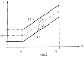
Фиг. 2 представляет зависимость величины верхних и нижних порогов потребляемого двигателем тока от скорости;
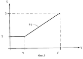
Фиг. 3 предоставляет зависимость степени открытия нефтевыводного штуцера от скорости двигателя;
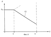
Фиг. 4 представляет зависимость давления на входе газовыводного штуцера от скорости двигателя;
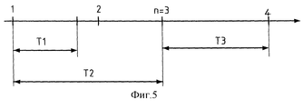
Фиг.5 представляет хрономограмму попыток пуска двигателя.FIG. 1 schematically depicts a well producing hydrocarbons in the form of oil and gas, activated by a submersible pumping system;
FIG. 2 represents the dependence of the magnitude of the upper and lower thresholds of the current consumed by the motor on speed;
FIG. 3 provides a relationship between the degree of opening of the oil outlet fitting and engine speed;
FIG. 4 represents the dependence of the inlet pressure of the gas outlet fitting on engine speed;
5 is a chronogram of engine starting attempts.
В наиболее общей формулировке способ изобретения используется для эксплуатации скважины, осуществляющей добычу углеводородов, активированную системой подкачки. In the most general formulation, the method of the invention is used to operate a well operating a hydrocarbon production activated by a booster system.
На фиг. 1 показана добывающая углеводороды скважина, которая содержит трубчатую выкидную колонну 1, которая соединяет дно 31 скважины, расположенное на уровне коллектора 30 углеводородов, с устьем скважины, расположенным в ее верхней части, трубу 2, концентрическую по отношению к колонне 1, которая облицовывает стенку скважины и имеет в своей нижней части множество отверстий 4, через которые углеводороды поступают из коллектора на дно 31 скважины, насос 5, погруженный в углеводороды, находящиеся на дне 31 скважины, гидравлический выход которого соединен с нижним концом выкидной колонны 1, предназначенной для подъема углеводородов, электродвигатель 6, механически связанный с насосом 5 и имеющий контакты для подвода электропитания 13, частотный вариатор 10, имеющий выводные контакты 11, питаемый с помощью кабеля 12 от электросети (на фиг.1 не показан). In FIG. 1 shows a hydrocarbon producing well that includes a tubular flow column 1 that connects a bottom 31 of a well located at the level of a hydrocarbon collector 30 to a wellhead located at its upper part, a
Питательный кабель 7 электродвигателя 6 соединяет выводные контакты 11 частотного вариатора 10 с контактами 13 для электропитания двигателя 6. Датчик 8 обратного вращения расположен на кабеле 7 и подает на выходе электрический сигнал в том случае, когда насос 5 вращается в направлении, обратном его нормальному направлению вращения. Датчик тока 9 подает на выход электрический сигнал, характеризующий ток, потребляемый двигателем 6. Нефтевыводная магистраль 14 связана с верхней частью выкидной колонны 1, через которую добытая нефть подается на установку нефтеподготовки (на фиг. 1 не показано). Нефтевыводной штуцер 17 смонтирован на магистрали 14 и предназначен для регулирования дебита добываемой нефти. Привод 18 механически связан с штуцером 17 и снабжен вводом команд. Датчик 15 давления размещен на входе в штуцер 17 и подает на выход электрический сигнал, пропорциональный величине указанного давления. The power cable 7 of the electric motor 6 connects the output contacts 11 of the frequency variator 10 with the contacts 13 for powering the motor 6. The reverse rotation sensor 8 is located on the cable 7 and gives an electrical signal at the output when the pump 5 rotates in the direction opposite to its normal direction of rotation . The current sensor 9 supplies an electric signal output characterizing the current consumed by the engine 6. The oil output line 14 is connected to the upper part of the flow column 1 through which the extracted oil is supplied to the oil refining unit (not shown in Fig. 1). The oil outlet fitting 17 is mounted on line 14 and is designed to control the flow rate of produced oil. The drive 18 is mechanically connected to the fitting 17 and is equipped with input commands. A pressure sensor 15 is placed at the inlet to the fitting 17 and supplies an electrical signal proportional to the specified pressure.
Датчик 16 оценивает дебит нефти в магистрали 14 и оборудован пластиной с отверстием, введенной в магистраль 14, и датчиком для измерения дифференциального давления, создаваемого этой пластиной. The sensor 16 evaluates the oil flow rate in the line 14 and is equipped with a plate with a hole introduced into the line 14 and a sensor for measuring the differential pressure generated by this plate.
Газовыводная магистраль 19 соединена с верхней частью кольцевого пространства 3, через которое выводится избыток добываемого газа. Газовыводной штуцер 22 смонтирован на магистрали 19 и предназначен для регулирования дебита газа, выводимого через магистраль 19. Привод 23 механически связан со штуцером 22 и снабжен вводом команд. Датчик 15 давления размещен на входе в штуцер 22. Датчик 21 предназначен для замера дебита выводимого газа. The gas outlet line 19 is connected to the upper part of the
Программируемый автомат 24 содержит множество вводов: 25a, 25b, 25с, 25d, 25е, 25f и 25g и соединен соответственно с выводом 28 частотного вариатора 10 и датчиками 9, 8, 21, 20, 16 и 15 таким образом, что ряд выводов 26а, 26b и 26с связаны соответственно с вводом 27 частотного вариатора 10 и вводами команд приводов 18 и 23. Скважина содержит также устройство 29 для диалога оператора с автоматом 24. The programmable machine 24 contains many inputs: 25a, 25b, 25c, 25d, 25e, 25f and 25g and is connected respectively to the output 28 of the frequency variator 10 and the sensors 9, 8, 21, 20, 16 and 15 so that a number of outputs 26a, 26b and 26c are associated respectively with the input 27 of the frequency variator 10 and the command inputs of the drives 18 and 23. The well also includes a device 29 for dialogue between the operator and the machine 24.
Автомат 24, кроме того, содержит не изображенную на фиг.1 память, предварительно загруженную программой, и данными, необходимыми для эксплуатации скважины, в частности, все задаваемые значения переменных для регулирования. Эти значения предварительно вводятся оператором с помощью устройства 29 для диалога оператора с автоматом и модифицируются в процессе эксплуатации скважины с помощью того же устройства 29. The machine 24, in addition, contains the memory, not shown in FIG. 1, preloaded by the program and the data necessary for the operation of the well, in particular, all the set values of the variables for regulation. These values are pre-entered by the operator using the device 29 for the dialogue of the operator with the machine and are modified during the operation of the well using the same device 29.
Частотный вариатор 10, питаемый от электросети с постоянной частотой, подает на выводной контакт 11 электрическое напряжение переменной частоты, модифицируемой сигналом, приложенным к его вводу 27. Он содержит также контактор-разъединитель, позволяющий подавать напряжение на двигатель и отключать напряжение от двигателя 6, управляемого подачей на его ввод 27 электрического сигнала, возникающего на выводе 26а автомата. The frequency variator 10, powered by a constant frequency power supply, supplies the output terminal 11 with an alternating frequency electrical voltage, modified by the signal applied to its input 27. It also contains a contactor-disconnector, which allows voltage to be applied to the motor and to disconnect the voltage from the motor 6 controlled applying to its input 27 an electrical signal arising from terminal 26a of the machine.
Частотный вариатор 10 подает на свой вывод 28 сигнал, характеризующий частоту напряжения, приложенного к электродвигателю 6. Этот сигнал, приложенный к вводу 25а автомата, позволяет последнему рассчитать скорость двигателя 6. The frequency variator 10 supplies to its output 28 a signal characterizing the frequency of the voltage applied to the electric motor 6. This signal, applied to the input 25a of the machine, allows the latter to calculate the speed of the motor 6.
Поскольку скорость электродвигателя 6 пропорциональна частоте подаваемого напряжения, эту скорость можно регулировать с помощью автомата 24, используя сигнал на выводе 26а, соединенном с вводом 27 вариатора 10. Добывающая углеводороды скважина содержит также не показанное на фиг.1 защитное устройство, подсоединенное через свой вывод к вводу автомата 24. Защитное устройство состоит из заградительных щитов, раздельно смонтированных на выкидной колонне 1 и в кольцевом пространстве 3 и получающих командные сигналы через электронные модули, реализующие логические функции обеспечения безопасности скважины. Since the speed of the electric motor 6 is proportional to the frequency of the applied voltage, this speed can be controlled using the automaton 24, using the signal at terminal 26a connected to the input 27 of variator 10. The hydrocarbon producing well also contains a protective device (not shown in FIG. 1) connected through its terminal to the input of the machine 24. The protective device consists of barriers, separately mounted on the flow column 1 and in the
Способ эксплуатации скважины в период пуска скважины, т.е. при начале выдачи продукции, и в период повторного пуска после прекращения выдачи продукции включает нижеперечисленные стадии. The method of operating the well during the start-up period, i.e. at the beginning of the issuance of products, and during the restart period after the termination of the issuance of products includes the following stages.
Подготовительная стадия, в течение которой автомат 24 осуществляет следующее. The preparatory stage, during which the machine 24 performs the following.
Определяет с помощью алгоритма регуляции на основе сигнала, выдаваемого датчиком 20 давления, расположенным перед газовыводным штуцером 22, передаточное число привода 23 для доведения упомянутого давления до его заданного пускового значения;
определяет с помощью алгоритма регуляции на основе сигнала, выдаваемого датчиком 15 давления, расположенным перед нефтевыводным штуцером 17, передаточное число привода 18 для доведения упомянутого давления до его заданного пускового значения;
затем подает на вывод 26b командный сигнал привода 18 для закрытия нефтевыводного штуцера 17;
после этого проверяет при отключенном от сети электродвигателе, является ли состояние насоса 5 соответствующим пуску без риска механической поломки, т. е. является ли насос 5 в состоянии остановки или вращается в направлении нормального вращения, что позволяет перемещать вверх углеводороды, засосанные на дне скважины. В противном случае, если насос 5 вращается в направлении, противоположном направлению нормального вращения, под действием естественной циркуляции углеводородов, сигнал, выдаваемый датчиком 8, интерпретируется автоматом как запрет запускать двигатель 6;
проверяет превосходит ли промежуток между двумя последовательными попытками пуска некоторое заданное время Т1, чтобы не допустить перегревов. С этой целью после каждого пуска автомат включает счетчик времени, содержимое которого при следующем пуске он сравнивает с заданной величиной Т1, основываясь на рекомендациях конструктора двигателя 6 и условиях, в которых он работает, и сохраняет зафиксированное время в качестве данных;
проверяет, чтобы после числа попыток пуска n=3 в течение времени Т2 четвертая (n+1) попытка не производилась до истечения времени Т3, обеспечивающего охлаждения двигателя. Значения T1, T2 и Т3 задаются на основании характеристик двигателя и представлены на хронограмме фиг.5. Стадия начала выдачи продукции, в течение которой автомат 24 осуществляет следующее:
- подает на вывод 26а сигнал для постепенного запитывания двигателя 6 до тех пор, пока насос 5 не приобретет заданную скорость вращения;
- спустя некоторое время удостоверяется в том, что давление на входе нефтевыводного штуцера, измеряемое с помощью датчика давления 15, превышает заданный порог подъема давления;
- спустя некоторое время удостоверяется в том, что потребляемый двигателем 6 ток, измеряемый датчиком 9, превышает заданный порог;
- допускает вращение насоса 5, если эти два порога превышены, и в противном случае останавливает насос 5, посылая команду остановки частотному вариатору 10;
- постепенно увеличивает степень открытия нефтевыводного штуцера 17 до заданного значения;
- ожидает в течение заданного стабилизационного периода;
- контролирует надежную работу скважины путем одновременной проверки потребляемого двигателем 6 тока и производительности скважины, используя по меньшей мере один показатель производительности;
- регулирует давление на входе газовыводного штуцера 22 до заданного значения путем воздействия на этот штуцер.Using the control algorithm, determines the gear ratio of the actuator 23 to bring said pressure to its predetermined starting value based on the signal generated by the pressure sensor 20 located in front of the gas outlet fitting 22;
determines, using the control algorithm, based on the signal generated by the pressure sensor 15 located in front of the oil outlet fitting 17, the gear ratio of the actuator 18 to bring said pressure to its predetermined starting value;
then provides the output signal 26b command signal of the actuator 18 to close the oil outlet 17;
after that, when the electric motor is disconnected from the mains, it checks whether the state of pump 5 is appropriate to start without the risk of mechanical failure, i.e., whether pump 5 is in a stopped state or rotates in the direction of normal rotation, which allows hydrocarbons sucked up at the bottom of the well to be moved up. Otherwise, if the pump 5 rotates in the opposite direction to the normal rotation due to the natural circulation of hydrocarbons, the signal generated by the sensor 8 is interpreted by the machine as a prohibition to start the engine 6;
checks whether the interval between two consecutive start attempts exceeds a predetermined time T1 to prevent overheating. To this end, after each start-up, the machine includes a time counter, the contents of which at the next start, it compares with the set value T1, based on the recommendations of the engine designer 6 and the conditions under which it operates, and saves the recorded time as data;
checks that after the number of start-up attempts n = 3 during time T2, the fourth (n + 1) attempt is not made until time T3, which provides engine cooling, expires. The values T1, T2 and T3 are set based on the characteristics of the engine and are presented in the chronogram of FIG. 5. The stage of beginning of the issuance of products, during which the machine 24 performs the following:
- sends a signal to terminal 26a to gradually power the engine 6 until the pump 5 acquires a predetermined rotation speed;
- after some time, it is ascertained that the pressure at the inlet of the oil outlet connection, measured with the pressure sensor 15, exceeds a predetermined pressure rise threshold;
- after some time, it is ascertained that the current consumed by the motor 6, measured by the sensor 9, exceeds a predetermined threshold;
- allows the rotation of the pump 5, if these two thresholds are exceeded, and otherwise stops the pump 5, sending a stop command to the frequency variator 10;
- gradually increases the degree of opening of the oil outlet 17 to a predetermined value;
- expects for a given stabilization period;
- controls the reliable operation of the well by simultaneously checking the current consumed by the motor 6 and the well productivity using at least one productivity indicator;
- adjusts the pressure at the inlet of the gas outlet fitting 22 to a predetermined value by acting on this fitting.
Наряду с обычно осуществляемыми проверками, состоящими в сравнении потребляемого двигателем 6 тока с независимыми один от другого высшим и низшим порогами скорости двигателя, преодоление одного из которых приводит к остановке насоса, автомат 24 сравнивает этот ток с некоторым нижним порогом. Along with the usually performed checks, which consist in comparing the current consumed by the motor 6 with the higher and lower thresholds of the motor speed independent of one another, overcoming one of which leads to a pump stop, the machine 24 compares this current with a certain lower threshold.
В случае преодоления этого порога и при условии, что период сохранения этого преодоления превышает некоторое предусмотренное время, автомат 24 останавливает насос 5, посылая команды, принимаемые частотным вариатором 10. In case of overcoming this threshold and provided that the period of preservation of this overcoming exceeds a certain stipulated time, the machine 24 stops the pump 5, sending commands received by the frequency variator 10.
Автомат проверяет также устойчивость потребляемого двигателем 6 тока для обнаружения неустойчивостей. Проверка состоит в установлении того, что потребляемый двигателем 6 ток не выходит за пределы верхних и нижних пределов определенное количество раз в течение данного времени. Эти различные параметры определяются с учетом характеристик двигателя 6 и насоса 5. The machine also checks the stability of the current consumed by the motor 6 to detect instabilities. The check consists in establishing that the current consumed by the motor 6 does not go beyond the upper and lower limits a certain number of times during a given time. These various parameters are determined taking into account the characteristics of the engine 6 and pump 5.
В случае обнаружения неустойчивости автомат останавливает насос 5, посылая команду, принимаемую вариатором скорости 10. In the event of instability, the machine stops the pump 5, sending a command received by the speed variator 10.
Для осуществления проверок производительности скважины автомат 24 сравнивает дебит нефти на выходе, замеряемый датчиком 16, соединенным с вводом автомата 25f, с экспериментально установленным пороговым значением. Преодоление этого порога свидетельствует об эффективной работе, если это превышение сохраняется достаточно долго, не принимая в расчет кратковременные переходы порога, которые не рассматриваются как нарушения. В случае преодоления порога автомат дает команду частотному вариатору остановить насос 5. To perform well productivity checks, the machine 24 compares the output oil flow rate, measured by a sensor 16 connected to the input of the machine 25f, with an experimentally set threshold value. Overcoming this threshold indicates effective operation if this excess persists long enough, without taking into account short-term threshold transitions that are not considered violations. In case of overcoming the threshold, the machine instructs the frequency variator to stop pump 5.
Таким образом, благодаря изобретению при повторном пуске скважины нефтевыводной штуцер 17 не остается закрытым, что могло бы привести к перегреву и повреждению двигателя. Thus, thanks to the invention, when the well is restarted, the oil outlet 17 does not remain closed, which could lead to overheating and damage to the engine.
Во время послепускового периода, согласно изобретению, автомат 24 выполняет одновременно следующие операции. During the post-launch period, according to the invention, the machine 24 simultaneously performs the following operations.
Подает на вывод 26а сигнал повышения частоты вариатора 10 для увеличения скорости двигателя 6 до значения заранее установленной проектной скорости для достижения желаемого дебита нефти. Этот дебит может быть зафиксирован в виде величины, вводимой в автомат 24 или модуль в зависимости от условий работы установки подготовки углеводородного продукта, куда направляется добытый продукт;
подает на вывод 26b сигнал, дающий команду приводу 18 открыть нефтевыводной штуцер 17 до степени открытия, зависящей от проектной величины скорости, рассчитываемой по следующей формуле:
S(нефт)=α(V-Vmin)+Smin
при Vmin<V<Vmax,
где S(нефт) - степень открытия нефтевыводного штуцера;
V - заданное значение скорости электродвигателя 6;
α- константа, определяемая по формуле
![]()
Smin, Smax - соответственно степень минимального и максимального открытия нефтевыводного штуцера при минимальной и максимальной скорости электродвигателя;
Vmin и Vmax - соответственно минимальная и максимальная скорости двигателя,
α, Smin, Smax, Vmin и Vmax определяются на основе характеристик скважины, насоса и электродвигателя;
при этом фиг. 3 представляет в форме кривой 44 зависимость величины S(нефт) - степени открытия нефтевыводного штуцера 17 от проектной величины скорости V двигателя 7;
подает на вывод 26с сигнал, дающий команду приводу 23 поддерживать давление на входе газовыводного штуцера 22 на уровне, зависящем от проектной величины скорости, рассчитываемой по следующей формуле:
Р(газ)=β(V-Vmin)+Ро
при Vmin<V<Vmax,
где Р(газ) - давление на входе в газовыводной штуцер 22, измеряемое датчиком 20,
V - заданное значение скорости электродвигателя 6;
β- константа, определяемая по формуле
![]()
Ро и P1 - значения давления газа на входе газовыводного штуцера, соответствующие минимальной и максимальной скорости электродвигателя;
Vmin и Vmax - соответственно минимальная и максимальная скорости электродвигателя;
β, Ро, P1, Vmin и Vmax определяются на основе характеристик скважины, насоса и электродвигателя;
при этом фиг. 4 представляет в форме кривой 45 зависимость величины S(газ) - давления на входе газовыводного штуцера 22 от проектной величины скорости V электродвигателя 6;
регулирует надежность работы скважины, осуществляя одновременно проверку потребляемого электродвигателем 6 тока и проверку производительности скважины с использованием показателя производительности.It supplies output 26a with a signal to increase the frequency of variator 10 to increase the speed of engine 6 to a value of a predetermined design speed to achieve the desired oil production rate. This flow rate can be fixed in the form of a value entered into the machine 24 or module depending on the operating conditions of the hydrocarbon product preparation unit where the extracted product is sent;
sends a signal to terminal 26b instructing the drive 18 to open the oil outlet 17 to an opening degree depending on the design speed value calculated by the following formula:
S (oil) = α (V-Vmin) + Smin
for Vmin <V <Vmax,
where S (oil) is the degree of opening of the oil outlet fitting;
V is the set value of the speed of the electric motor 6;
α- constant determined by the formula
![]()
Smin, Smax - respectively, the degree of minimum and maximum opening of the oil outlet at the minimum and maximum speed of the electric motor;
Vmin and Vmax are the minimum and maximum engine speeds, respectively
α, Smin, Smax, Vmin, and Vmax are determined based on the characteristics of the well, pump, and electric motor;
wherein FIG. 3 represents, in the form of a
sends a signal to terminal 26c, instructing the actuator 23 to maintain the pressure at the inlet of the gas outlet fitting 22 at a level depending on the design speed value calculated by the following formula:
P (gas) = β (V-Vmin) + Po
for Vmin <V <Vmax,
where P (gas) is the pressure at the inlet to the gas outlet fitting 22, measured by the sensor 20,
V is the set value of the speed of the electric motor 6;
β- constant determined by the formula
![]()
Po and P 1 - gas pressure values at the inlet of the gas outlet fitting, corresponding to the minimum and maximum speed of the electric motor;
Vmin and Vmax are the minimum and maximum speeds of the electric motor, respectively;
β, Po, P 1 , Vmin and Vmax are determined based on the characteristics of the well, pump and electric motor;
wherein FIG. 4 represents in the form of a
regulates the reliability of the well, simultaneously checking the current consumed by the electric motor 6 and checking the productivity of the well using a performance indicator.
Для осуществления проверки потребляемого электродвигателем 6 тока автомат сравнивает величину этого тока с верхним и нижним порогами, зависящими от скорости электродвигателя 6. Эти пороги рассчитывают по следующим формулам:
I(верх)=INmin+γ(V-Vmin)+ΔI
при Vmin<V<Vmax;
I(нижн)=INmin+γ(V-Vmin)-ΔI
при Vmin<V<Vmax,
где I(верх) - верхний порог потребляемого двигателем 6 тока;
I(нижн) - нижний порог потребляемого двигателем 6 тока;
V - скорость электродвигателя 6, которая известна автомату по значению частоты вариатора 10;
INmin и INmax - соответственно минимальное и максимальное значения потребляемого электродвигателем тока;
Vmin и Vmax - соответственно минимальная и максимальная скорости двигателя, определяемые на основе характеристик скважины, насоса 5 и электродвигателя 6;
γ и ΔI - константы, рассчитываемые для каждой скважины с учетом характеристик электродвигателя 6 и его эффективного охлаждения перекачиваемыми углеводородами,
![]()
ΔI является допустимым отклонением величины потребляемого электродвигателем тока от его теоретического значения, обеспечивающим нормальную работу скважины.To check the current consumed by the electric motor 6, the machine compares the value of this current with the upper and lower thresholds, depending on the speed of the electric motor 6. These thresholds are calculated by the following formulas:
I (top) = INmin + γ (V-Vmin) + ΔI
for Vmin <V <Vmax;
I (lower) = INmin + γ (V-Vmin) -ΔI
for Vmin <V <Vmax,
where I (top) is the upper threshold of the current consumed by the motor 6;
I (lower) - the lower threshold of the current consumed by the motor 6;
V is the speed of the electric motor 6, which is known to the machine by the value of the frequency of the variator 10;
INmin and INmax are the minimum and maximum values of the current consumed by the electric motor, respectively;
Vmin and Vmax are the minimum and maximum engine speeds, respectively, determined on the basis of the characteristics of the well, pump 5 and electric motor 6;
γ and ΔI are constants calculated for each well, taking into account the characteristics of the electric motor 6 and its effective cooling by pumped hydrocarbons,
![]()
ΔI is the permissible deviation of the current consumed by the electric motor from its theoretical value, ensuring the normal operation of the well.
Фиг. 2 представляет в форме кривых 40 и 41 соответственно зависимости значений I(верх) и I(нижн) верхнего и нижнего порогов потребляемого электродвигателем 6 тока от скорости V двигателя. Интервалы 42 и 43 изменений величины I представляют соответственно ΔI и -ΔI. В случае преодоления порога автомат снижает скорость электродвигателя 6 до заданного значения и, если это преодоление сохраняется долее предусмотренного времени, останавливает насос 5, давая команду частотному вариатору 10. FIG. 2 represents in the form of
Автомат проверяет также устойчивость потребляемого двигателем 6 тока в послепусковой период с целью выявления неустойчивостей, которые характерны для быстрых изменений в потоке углеводородов, возникающих, например, из-за наличия избыточного газа на уровне насоса, что, в частности, может привести к поломкам электродвигателя 6 и насоса 5. Названная проверка состоит в том, чтобы удостовериться, что потребляемый двигателем 6 ток не превышает некоторый верхний предел определенное число раз в течение данного времени. Эти различные параметры определяются с учетом характеристик двигателя 6 и насоса 5. The machine also checks the stability of the current consumed by the motor 6 in the post-launch period in order to detect instabilities that are characteristic of rapid changes in the flow of hydrocarbons that occur, for example, due to the presence of excess gas at the pump level, which, in particular, can lead to breakdowns of the electric motor 6 and pump 5. The named test is to make sure that the current consumed by motor 6 does not exceed a certain upper limit a certain number of times during a given time. These various parameters are determined taking into account the characteristics of the engine 6 and pump 5.
В случае обнаружения неустойчивости автомат снижает скорость электродвигателя 6 до заданного значения и в случае продолжительной неустойчивости останавливает насос 5, давая команду, принимаемую частотным вариатором 10. In the event of instability detection, the machine reduces the speed of the electric motor 6 to a predetermined value and, in the case of prolonged instability, stops the pump 5, giving the command received by the frequency variator 10.
Для осуществления проверок производительности скважины автомат 24 сравнивает дебит нефти на выходе, замеряемый датчиком 16, соединенным с вводом автомата 25f, с заданными верхними и нижними порогами. Выход за рамки одного из этих порогов свидетельствует об эффективной работе, если этот выход длится в течение минимального времени, при этом кратковременные выходы за рамки порогов не свидетельствуют о ненормальной работе. Если происходит выход за рамки порога, автомат снижает скорость двигателя, а если же выход за рамки порога принимает устойчивый характер, дает команду частотному вариатору остановить насос 5. To perform well productivity checks, the machine 24 compares the output oil flow rate, measured by a sensor 16 connected to the input of the machine 25f, with predetermined upper and lower thresholds. Going beyond one of these thresholds indicates effective operation if this exit lasts for a minimum time, while short-term going beyond the thresholds does not indicate abnormal operation. If going beyond the threshold, the machine reduces the speed of the engine, but if going beyond the threshold takes a stable character, it instructs the frequency variator to stop pump 5.
Способ эксплуатации скважины, согласно изобретению, включает также координацию действий, связанных с работой скважины, с действиями по организации ее защиты. Когда защитное устройство запускает ряд действий, связанных с безопасностью работы, оно одновременно подает сигнал на вывод, соединенный с вводом автомата 24. Последний расшифровывает этот сигнал и подает команды закрытия нефте- и газовыводного штуцеров и остановки электродвигателя 6, что повышает эффективность мер по обеспечению безопасной работы. Другим преимуществом настоящего изобретения является защита насоса от чрезмерного или слишком долгого открытия нефтевыводного штуцера, которые могли бы не соответствовать характеристикам насоса. Изобретение позволяет также осуществлять работу насоса в присутствии свободного газа, так как оно гарантирует своими активными контролирующими действиями приемлемые условия работы скважины. A method of operating a well, according to the invention, also includes coordinating actions associated with the operation of the well with actions to organize its protection. When the protective device starts a series of actions related to safe operation, it simultaneously sends a signal to the output connected to the input of the machine 24. The latter decrypts this signal and gives commands to close the oil and gas outlet fittings and stop the electric motor 6, which increases the efficiency of measures to ensure safe work. Another advantage of the present invention is the protection of the pump from excessive or too long opening of the oil outlet, which might not meet the characteristics of the pump. The invention also allows the pump to operate in the presence of free gas, since it guarantees acceptable working conditions of the well with its active controlling actions.
Благодаря способу, согласно изобретению, насос защищен от обусловленных перегревом поломок при всех режимах работы, особенно при работе на малой скорости в пусковой и эксплуатационный периоды работы скважины, обеспечивая максимальную добычу углеводородов. Thanks to the method according to the invention, the pump is protected from breakdowns caused by overheating under all operating conditions, especially when operating at low speed during the start-up and operational periods of well operation, ensuring maximum hydrocarbon production.
Изобретение позволяет также защитить оборудование скважины, особенно двигатель насоса, от механических или гидравлических ударов благодаря одновременному воздействию нефте- и газовыводного штуцеров на скорость двигателя. The invention also makes it possible to protect well equipment, especially a pump engine, from mechanical or hydraulic shocks due to the simultaneous effect of oil and gas outlets on engine speed.
ПРИМЕР
В качестве примера ниже приводятся значения параметров, используемых для реализации способа эксплуатации и скважины, добывающей углеводороды из коллектора, расположенного на глубине 650 метров, статическое давление на дне которого составляет 50 бар. Эта скважина, оборудованная трубчатой выкидной колонной диаметром 114 мм, окруженной концентрической трубой диаметром 244 мм, активирована системой подкачки, состоящей из расположенного на дне скважины погружного насоса, имеющего 36 ступеней и приводимого в действие электродвигателем мощностью 200 кВт.EXAMPLE
As an example, the values of the parameters used to implement the method of operation and the well producing hydrocarbons from a reservoir located at a depth of 650 meters, the static pressure at the bottom of which is 50 bar, are given below. This well, equipped with a 114 mm diameter tubular flow collar surrounded by a concentric pipe with a diameter of 244 mm, is activated by a booster system consisting of a submersible pump located at the bottom of the well, which has 36 stages and is driven by a 200 kW electric motor.
Электропитание двигателя обеспечивается частотным вариатором мощностью 360 кВт, обеспечивающим рабочий диапазон от 1600 до 2700 м3/сутки перекаченных углеводородов. Частота тока, выдаваемая частотным вариатором, варьирует от 47 до 61 Гц, что соответствует минимальной скорости 2740 и максимальной 3560 оборотов в минуту.The engine is powered by a frequency variator with a capacity of 360 kW, providing an operating range from 1600 to 2700 m 3 / day of pumped hydrocarbons. The frequency of the current issued by the frequency variator varies from 47 to 61 Hz, which corresponds to a minimum speed of 2740 and a maximum of 3560 rpm.
Номинальная сила тока, потребляемого двигателем, составляет 77 А при 50 Гц и напряжении 2000 В. Проектная скорость равна максимальной скорости двигателя. The rated current consumed by the motor is 77 A at 50 Hz and a voltage of 2000 V. The design speed is equal to the maximum motor speed.
После повторного пуска, следующего за остановкой добычи продукта, в течение подготовительной стадии пускового периода давление на входе в газовыводной штуцер доводится до 20 бар, а давление на входе в нефтевыводной штуцер до 17 бар. After the restart, following the stop of the production of the product, during the preparatory stage of the start-up period, the pressure at the inlet to the gas outlet is brought to 20 bar, and the pressure at the inlet to the oil outlet to 17 bar.
Минимальное время между двумя последовательными попытками составляет 20 мин. The minimum time between two consecutive attempts is 20 minutes.
Минимальное ожидание после трех попыток пуска, произведенных в интервале 120 мин, составляет 60 мин. The minimum expectation after three start-up attempts made in the interval of 120 minutes is 60 minutes.
В течение периода входа в режим добычи продукта минимальная скорость, достигаемая двигателем при постепенном увеличении тока, соответствует подаваемой частоте 48 Гц и составляет 2740 об/мин. Порог подъема давления на входе в нефтевыводной штуцер составляет 20 бар, а порог, который должен быть превышен потребляемым двигателем током, составляет 36 А. Достигаемая после постепенного увеличения степень открытия нефтевыводного штуцера составляет 70%. Нижний предел, с которым сравнивают потребляемый двигателем ток при проверке этого тока с целью обеспечения надежной работы, составляет 36 А. During the period of entering the product production mode, the minimum speed achieved by the engine with a gradual increase in current corresponds to a supplied frequency of 48 Hz and is 2740 rpm. The threshold for raising the pressure at the inlet to the oil outlet is 20 bar, and the threshold that must be exceeded by the current consumed by the motor is 36 A. The degree of opening of the oil outlet, achieved after a gradual increase, is 70%. The lower limit with which the current consumed by the motor is compared when checking this current to ensure reliable operation is 36 A.
Устойчивость потребляемого двигателем тока проверяют, удостоверяясь в том, что величина этого тока не превышает более пяти раз в течение одной минуты среднее значение, рассчитанное для интервала времени 60 с плюс 3 А. The stability of the current consumed by the motor is checked, making sure that the value of this current does not exceed more than five times in one minute the average value calculated for a time interval of 60 s plus 3 A.
Порог, с которым сравнивают показатель производительности, выбранный для контроля надежности работы и представляющий собой перепад давления, которому соответствует дебит нефти, равен 1000 м3/сутки. Давление на входе в газовыводной штуцер регулируют до заданного пускового значения, т.е. до 20 бар. После стадии пуска скорость двигателя увеличивают до проектного значения, которое достигается путем регулирования частоты подаваемого тока до 61 Гц, что соответствует 3560 об/мин.The threshold with which the performance indicator is compared, selected to control the reliability of operation and representing the pressure drop, which corresponds to the oil flow rate, is equal to 1000 m 3 / day. The pressure at the inlet to the gas outlet fitting is regulated to a predetermined starting value, i.e. up to 20 bar. After the start-up stage, the engine speed is increased to the design value, which is achieved by adjusting the frequency of the supplied current to 61 Hz, which corresponds to 3560 rpm.
Одновременно нефтевыводной штуцер открывают до степени открытия, зависящей от скорости в соответствии со следующей формулой:
S(нефт)=α(V-Vmin)+Smin
при Vmin<V<Vmax,
где S(нефт) - степень открытия нефтевыводного штуцера;
V - заданное значение скорости электродвигателя;
α - константа, равная 0,036;
Smin - степень минимального открытия нефтевыводного штуцера, равная 70%,
Vmin=2740 об/мин и Vmax=3560 об/мин - соответственно минимальная и максимальная скорости электродвигателя.At the same time, the oil outlet fitting is opened to a degree of opening depending on speed in accordance with the following formula:
S (oil) = α (V-Vmin) + Smin
for Vmin <V <Vmax,
where S (oil) is the degree of opening of the oil outlet fitting;
V is the set value of the speed of the electric motor;
α is a constant equal to 0.036;
Smin - the degree of minimum opening of the oil outlet, equal to 70%,
Vmin = 2740 rpm and Vmax = 3560 rpm - respectively, the minimum and maximum speeds of the electric motor.
Таким образом, получают S(нефт)=100%. Thus, S (oil) = 100% is obtained.
Степень открытия газовыводного штуцера регулируют таким образом, чтобы поддерживать давление на входе в этот штуцер на уровне, рассчитываемом как функцию скорости электродвигателя по следующей формуле:
Р(газ)=β(V-Vmin)+Ро
при Vmin<V<Vmax,
где Р(газ) - давление на входе в газовыводной штуцер;
V - заданное проектное значение скорости электродвигателя,
β - константа, равная 0,01;
Ро - давление газа, равное 20 бар, соответствующее минимальной скорости электродвигателя,
Vmin= 2740 об/мин и Vmax= 3560 об/мин - соответственно минимальная и максимальная скорости электродвигателя.The degree of opening of the gas outlet fitting is controlled in such a way as to maintain the pressure at the inlet of this fitting at a level calculated as a function of the speed of the electric motor according to the following formula:
P (gas) = β (V-Vmin) + Po
for Vmin <V <Vmax,
where P (gas) is the pressure at the inlet to the gas outlet fitting;
V is the specified design value of the speed of the electric motor,
β is a constant equal to 0.01;
Po - gas pressure equal to 20 bar, corresponding to the minimum speed of the electric motor,
Vmin = 2740 rpm and Vmax = 3560 rpm - respectively, the minimum and maximum speeds of the electric motor.
Пороги потребляемого двигателем тока, используемые для проверок этого тока, рассчитывают по следующим формулам:
I(верх)=INmin+γ(V-Vmin)+ΔI
при Vmin<V<Vmax;
I(нижн)=INmin+γ(V-Vmin)-ΔI
при Vmin<V<Vmax,
в которых I(верх) - верхний порог потребляемого двигателем тока;
I(нижн) - нижний порог потребляемого двигателем тока;
V - скорость электродвигателя в об/мин;
INmin - минимальное значение потребляемого электродвигателем тока, равное 40 А,
Vmin= 3560 об/мин и Vmax= 3560 об/мин - соответственно минимальная и максимальная скорости двигателя, определяемые на основе характеристик скважины, насоса и двигателя,
γ= 0,034 и ΔI=4 А - константы, рассчитываемые для каждой скважины на основе характеристик двигателя и его эффективного охлаждения перекачиваемыми углеводородами.The thresholds of the current consumed by the motor, used to check this current, are calculated by the following formulas:
I (top) = INmin + γ (V-Vmin) + ΔI
for Vmin <V <Vmax;
I (lower) = INmin + γ (V-Vmin) -ΔI
for Vmin <V <Vmax,
in which I (top) is the upper threshold of the current consumed by the motor;
I (lower) - the lower threshold of the current consumed by the motor;
V is the speed of the electric motor in rpm;
INmin - the minimum value of the current consumed by the electric motor, equal to 40 A,
Vmin = 3560 rpm and Vmax = 3560 rpm - respectively, the minimum and maximum engine speeds, determined on the basis of the characteristics of the well, pump and engine,
γ = 0.034 and ΔI = 4 A are constants calculated for each well based on the characteristics of the engine and its effective cooling by pumped hydrocarbons.
Устойчивость потребляемого двигателем тока проверяют, удостоверяясь в том, что величина этого тока не превышает более пяти раз в течение одной минуты среднее значение, рассчитанное для интервала времени 60 с и увеличиваемое в пусковой период на 3 А. The stability of the current consumed by the motor is checked, making sure that the value of this current does not exceed more than five times in one minute, the average value calculated for a time interval of 60 s and increased in the starting period by 3 A.
После достижения проектной скорости показатель производительности, выраженной в виде дебита нефти, сопоставляют с порогами 2400 и 3000 м3/сутки.After reaching the design speed, the performance indicator, expressed as oil flow rate, is compared with thresholds of 2400 and 3000 m 3 / day.
Значение, до которого понижают скорость в случае перехода порога с целью обеспечения надежной работы, равно значению скорости, соответствующей частоте подаваемого тока, равной 47 Гц, т.е. 2740 об/мин. The value to which the speed is reduced in the event of a threshold crossing in order to ensure reliable operation is equal to the speed value corresponding to the frequency of the supplied current equal to 47 Hz, i.e. 2740 rpm.
Во время и после пускового периода не зависящие от скорости двигателя высший и нижний пороги составляют 80 и 36 А. During and after the start-up period, the upper and lower thresholds, independent of engine speed, are 80 and 36 A.
Claims (20)
S(нефт)= α(V-Vmin)+Smin,
при Vmin<V<Vmax,
где S(нефт) - степень открытия нефтевыводного штуцера;
V - заданное значение скорости электродвигателя;
α - константа;
Smin - степень минимального открытия нефтевыводного штуцера при минимальной скорости электродвигателя;
Vmin и Vmax - соответственно, минимальная и максимальная скорости электродвигателя,
α, Smin, Vmin и Vmax определяются на основе характеристик скважины, насоса и электродвигателя.6. The method according to p. 5, characterized in that the degree of opening of the oil outlet fitting is calculated by the following formula:
S (oil) = α (V-Vmin) + Smin,
for Vmin <V <Vmax,
where S (oil) is the degree of opening of the oil outlet fitting;
V is the set value of the speed of the electric motor;
α is a constant;
Smin - the degree of minimum opening of the oil outlet at the minimum speed of the electric motor;
Vmin and Vmax - respectively, the minimum and maximum speeds of the electric motor,
α, Smin, Vmin, and Vmax are determined based on the characteristics of the well, pump, and motor.
Р(газ)= β(V-Vmin)+Po,
при Vmin<V<Vmax,
где Р(газ) - давление на входе в газовыводной штуцер;
V - проектная величина скорости электродвигателя;
β - константа;
Po - значение давления газа на входе газовыводного штуцера, соответствующее минимальной скорости электродвигателя;
Vmin и Vmax - соответственно, минимальная и максимальная скорости двигателя;
β, Po, Vmin и Vmax определяются на основе характеристик скважины, насоса и электродвигателя.7. The method according to p. 5, characterized in that the pressure at the inlet of the gas outlet fitting is calculated by the following formula:
P (gas) = β (V-Vmin) + Po,
for Vmin <V <Vmax,
where P (gas) is the pressure at the inlet to the gas outlet fitting;
V is the design value of the speed of the electric motor;
β is a constant;
Po is the gas pressure at the inlet of the gas outlet fitting, corresponding to the minimum speed of the electric motor;
Vmin and Vmax - respectively, the minimum and maximum engine speeds;
β, Po, Vmin, and Vmax are determined based on the characteristics of the well, pump, and motor.
I(верх)= INmin+γ(V-Vmim)+Δ1,
при Vmin<V<Vmax;
I(нижн)= INmin+γ(V-Vmin)-Δ1,
при Vmin<V<Vmax,
где I(верх) - верхний порог потребляемого электродвигателем тока;
I(нижн) - нижний порог потребляемого электродвигателем тока;
V - скорость электродвигателя;
INmin - минимальное значение потребляемого электродвигателем тока при соответственно минимальной скорости электродвигателя;
Vmin и Vmax - соответственно, минимальная и максимальная скорости электродвигателя, определяемые на основе характеристик скважины, насоса и электродвигателя;
γ и Δ1 - константы, рассчитываемые для каждой скважины на основе характеристик электродвигателя.9. The method according to p. 8, characterized in that the upper and lower thresholds of the current consumed by the electric motor, depending on the speed of the electric motor, are calculated by the following formulas:
I (top) = INmin + γ (V-Vmim) + Δ1,
for Vmin <V <Vmax;
I (lower) = INmin + γ (V-Vmin) -Δ1,
for Vmin <V <Vmax,
where I (top) is the upper threshold of the current consumed by the electric motor;
I (lower) - the lower threshold of the current consumed by the electric motor;
V is the speed of the electric motor;
INmin - the minimum value of the current consumed by the electric motor at the correspondingly minimum electric motor speed;
Vmin and Vmax - respectively, the minimum and maximum speeds of the electric motor, determined on the basis of the characteristics of the well, pump and electric motor;
γ and Δ1 are constants calculated for each well based on the characteristics of the electric motor.
S(нефт)= α(V-Vmin)+Smin,
при Vmin<V<Vmax,
где S(нефт) - степень открытия нефтевыводного штуцера;
V - заданное значение скорости электродвигателя;
α - константа;
Smin - степень минимального открытия нефтевыводного штуцера при минимальной скорости электродвигателя;
Vmin и Vmax - соответственно, минимальная и максимальная скорости электродвигателя;
α, Smin, Vmin и Vmax определяются на основе характеристик скважины, насоса и электродвигателя.14. The method according to p. 13, characterized in that the degree of opening of the oil outlet fitting is calculated by the following formula:
S (oil) = α (V-Vmin) + Smin,
for Vmin <V <Vmax,
where S (oil) is the degree of opening of the oil outlet fitting;
V is the set value of the speed of the electric motor;
α is a constant;
Smin - the degree of minimum opening of the oil outlet at the minimum speed of the electric motor;
Vmin and Vmax - respectively, the minimum and maximum speeds of the electric motor;
α, Smin, Vmin, and Vmax are determined based on the characteristics of the well, pump, and motor.
Р(газ)= β(V-Vmin)+Ро,
при Vmin<V<Vmax,
где Р(газ) - давление на входе в газовыводной штуцер;
V - проектная величина скорости электродвигателя;
β - константа;
Ро - значение давления газа на входе газовыводного штуцера, соответствующие минимальной скорости электродвигателя;
Vmin и Vmax - соответственно, минимальная и максимальная скорости двигателя;
β, Ро, Vmin и Vmax определяются на основе характеристик скважины, насоса и электродвигателя.15. The method according to p. 13, characterized in that the pressure at the inlet to the gas outlet fitting is calculated by the following formula:
P (gas) = β (V-Vmin) + Po,
for Vmin <V <Vmax,
where P (gas) is the pressure at the inlet to the gas outlet fitting;
V is the design value of the speed of the electric motor;
β is a constant;
Po is the value of the gas pressure at the inlet of the gas outlet fitting, corresponding to the minimum speed of the electric motor;
Vmin and Vmax - respectively, the minimum and maximum engine speeds;
β, Po, Vmin and Vmax are determined based on the characteristics of the well, pump and electric motor.
I(верх)= INmin+γ(V-Vmin)+Δ1,
при Vmin<V<Vmax;
I(нижн)= INmin+γ(V-Vmin)-Δ1,
при Vmin<V<Vmax,
где I(верх) - верхний порог потребляемого электродвигателем тока;
I(нижн) - нижний порог потребляемого электродвигателем тока;
V - скорость электродвигателя;
INmin - минимальное значение потребляемого электродвигателем тока;
Vmin и Vmax - соответственно, минимальная и максимальная скорости электродвигателя, определяемые на основе характеристик скважины, насоса и электродвигателя;
γ и Δ1 - константы, рассчитываемые для каждой скважины на основе характеристик электродвигателя.17. The method according to p. 16, characterized in that the upper and lower thresholds of the current consumed by the electric motor are calculated by the following formulas:
I (top) = INmin + γ (V-Vmin) + Δ1,
for Vmin <V <Vmax;
I (lower) = INmin + γ (V-Vmin) -Δ1,
for Vmin <V <Vmax,
where I (top) is the upper threshold of the current consumed by the electric motor;
I (lower) - the lower threshold of the current consumed by the electric motor;
V is the speed of the electric motor;
INmin - the minimum value of the current consumed by the electric motor;
Vmin and Vmax - respectively, the minimum and maximum speeds of the electric motor, determined on the basis of the characteristics of the well, pump and electric motor;
γ and Δ1 are constants calculated for each well based on the characteristics of the electric motor.
Applications Claiming Priority (2)
| Application Number | Priority Date | Filing Date | Title |
|---|---|---|---|
| FR9801782 | 1998-02-13 | ||
| FR9801782A FR2775018B1 (en) | 1998-02-13 | 1998-02-13 | METHOD OF CONDUCTING A WELL FOR PRODUCING OIL AND ACTIVE GAS BY A PUMPING SYSTEM |
Publications (2)
| Publication Number | Publication Date |
|---|---|
| RU99102971A RU99102971A (en) | 2000-12-20 |
| RU2216632C2 true RU2216632C2 (en) | 2003-11-20 |
Family
ID=9522969
Family Applications (1)
| Application Number | Title | Priority Date | Filing Date |
|---|---|---|---|
| RU99102971/06A RU2216632C2 (en) | 1998-02-13 | 1999-02-12 | Method of operation of well producing oil and gas and activated by pumping system (versions) |
Country Status (8)
| Country | Link |
|---|---|
| US (1) | US6119781A (en) |
| BR (1) | BR9900643A (en) |
| CA (1) | CA2260333C (en) |
| FR (1) | FR2775018B1 (en) |
| GB (1) | GB2334275B (en) |
| NO (1) | NO320870B1 (en) |
| OA (1) | OA11102A (en) |
| RU (1) | RU2216632C2 (en) |
Cited By (5)
| Publication number | Priority date | Publication date | Assignee | Title |
|---|---|---|---|---|
| RU2307920C1 (en) * | 2004-12-23 | 2007-10-10 | Шлюмбергер Текнолоджи Б.В. | Device and method for underground well completion |
| RU2309246C1 (en) * | 2006-02-02 | 2007-10-27 | Олег Марсович Гарипов | Downhole machine |
| RU2335626C1 (en) * | 2007-10-19 | 2008-10-10 | Открытое акционерное общество "Татнефть" им. В.Д. Шашина | Facility of well for simultaneous-separate operation of two beds |
| RU2376463C2 (en) * | 2007-08-15 | 2009-12-20 | Ненахов Станислав Михайлович | Oil production enterprise of hydrocarbon production field - of oil, oil-and gas and/or gas condensate field |
| RU2530175C2 (en) * | 2009-04-23 | 2014-10-10 | Тоталь С.А. | Method of hydrocarbons extraction from reservoir and hydrocarbons extraction plant |
Families Citing this family (23)
| Publication number | Priority date | Publication date | Assignee | Title |
|---|---|---|---|---|
| FR2783558B1 (en) * | 1998-09-21 | 2000-10-20 | Elf Exploration Prod | METHOD OF CONDUCTING AN ERUPTIVE-TYPE OIL PRODUCTION WELL |
| NO992947D0 (en) * | 1999-06-16 | 1999-06-16 | Jon Kore Heggholmen | Method and assembly of components for Õ extracting more oil and gas from oil / gas reservoirs |
| US6937923B1 (en) * | 2000-11-01 | 2005-08-30 | Weatherford/Lamb, Inc. | Controller system for downhole applications |
| NO20030599L (en) | 2002-02-11 | 2003-08-12 | Vetco Gray Scandinavia As | Integrated undersea power supply unit for drilling and production |
| GB2387977B (en) * | 2002-04-17 | 2005-04-13 | Abb Offshore Systems Ltd | Control of hydrocarbon wells |
| FR2840952A1 (en) * | 2002-06-13 | 2003-12-19 | Schlumberger Services Petrol | HYDROCARBON EXTRACTION PLANT FOR WELLS |
| US20080154510A1 (en) * | 2006-12-21 | 2008-06-26 | Chevron U.S.A. Inc. | Method and system for automated choke control on a hydrocarbon producing well |
| US20080203734A1 (en) * | 2007-02-22 | 2008-08-28 | Mark Francis Grimes | Wellbore rig generator engine power control |
| NO20072954A (en) * | 2007-06-11 | 2008-07-07 | Shore Tec Consult As | Gas-powered pumping device and method for pumping a liquid into a well |
| GB2450157B (en) | 2007-06-15 | 2011-12-21 | Baker Hughes Inc | System for determining an initial direction of rotation of an electrical submersible pump |
| FR2925569B1 (en) * | 2007-12-20 | 2010-01-22 | Total Sa | PROCESS FOR CONDUCTING A HYDROCARBON PRODUCTION WELL |
| US8155942B2 (en) * | 2008-02-21 | 2012-04-10 | Chevron U.S.A. Inc. | System and method for efficient well placement optimization |
| US8334666B2 (en) * | 2009-08-27 | 2012-12-18 | Baker Hughes Incorporated | Device, computer program product and computer-implemented method for backspin detection in an electrical submersible pump assembly |
| CN102787829B (en) * | 2011-05-20 | 2015-03-25 | 大港油田集团有限责任公司 | Fracturing and pump-free oil production integral process pipe column and operating method thereof |
| CN102747987A (en) * | 2012-07-04 | 2012-10-24 | 刘庆敏 | Sleeve gas collection device and method |
| US9528355B2 (en) * | 2013-03-14 | 2016-12-27 | Unico, Inc. | Enhanced oil production using control of well casing gas pressure |
| CA2944635A1 (en) | 2014-04-03 | 2015-10-08 | Schlumberger Canada Limited | State estimation and run life prediction for pumping system |
| CN105952420A (en) * | 2016-05-27 | 2016-09-21 | 中国石油天然气股份有限公司 | Sand control method for oil and gas wells |
| US10865635B2 (en) | 2017-03-14 | 2020-12-15 | Baker Hughes Oilfield Operations, Llc | Method of controlling a gas vent system for horizontal wells |
| US10947821B2 (en) * | 2017-08-23 | 2021-03-16 | Robert J. Berland | Oil and gas production well control system and method |
| US11649705B2 (en) * | 2017-08-23 | 2023-05-16 | Robert J Berland | Oil and gas well carbon capture system and method |
| CN114622896B (en) * | 2020-12-10 | 2025-01-28 | 中国石油天然气股份有限公司 | Oil well detection equipment |
| CN118815433B (en) * | 2024-09-20 | 2025-01-28 | 克拉玛依国勘石油技术有限公司 | A troubleshooting method, system, equipment, medium and product for profile control construction |
Citations (2)
| Publication number | Priority date | Publication date | Assignee | Title |
|---|---|---|---|---|
| RU2042796C1 (en) * | 1993-03-01 | 1995-08-27 | Николай Александрович Петров | Device for well hydraulic perforation |
| US5634522A (en) * | 1996-05-31 | 1997-06-03 | Hershberger; Michael D. | Liquid level detection for artificial lift system control |
Family Cites Families (12)
| Publication number | Priority date | Publication date | Assignee | Title |
|---|---|---|---|---|
| US34111A (en) * | 1862-01-07 | Improvement in printing-presses | ||
| USRE34111E (en) | 1983-01-18 | 1992-10-27 | Apparatus for operating a gas and oil producing well | |
| US4989671A (en) * | 1985-07-24 | 1991-02-05 | Multi Products Company | Gas and oil well controller |
| US4676313A (en) * | 1985-10-30 | 1987-06-30 | Rinaldi Roger E | Controlled reservoir production |
| US4798247A (en) * | 1987-07-15 | 1989-01-17 | Otis Engineering Corporation | Solenoid operated safety valve and submersible pump system |
| US5193985A (en) * | 1990-01-10 | 1993-03-16 | Uniflo Oilcorp, Ltd. | Pump control system for a downhole motor-pump assembly and method of using same |
| US6006832A (en) * | 1995-02-09 | 1999-12-28 | Baker Hughes Incorporated | Method and system for monitoring and controlling production and injection wells having permanent downhole formation evaluation sensors |
| FR2730767B1 (en) * | 1995-02-21 | 1997-04-18 | Inst Francais Du Petrole | METHOD AND DEVICE FOR REGULATING A POLYPHASIC PUMPING ASSEMBLY |
| US5823262A (en) * | 1996-04-10 | 1998-10-20 | Micro Motion, Inc. | Coriolis pump-off controller |
| US5819848A (en) * | 1996-08-14 | 1998-10-13 | Pro Cav Technology, L.L.C. | Flow responsive time delay pump motor cut-off logic |
| US5941305A (en) * | 1998-01-29 | 1999-08-24 | Patton Enterprises, Inc. | Real-time pump optimization system |
| US5967234A (en) * | 1998-05-02 | 1999-10-19 | Petroenergy Llc | Method of and device for production of hydrocarbons |
-
1998
- 1998-02-13 FR FR9801782A patent/FR2775018B1/en not_active Expired - Lifetime
-
1999
- 1999-02-04 US US09/244,047 patent/US6119781A/en not_active Expired - Lifetime
- 1999-02-09 GB GB9902741A patent/GB2334275B/en not_active Expired - Lifetime
- 1999-02-09 NO NO19990596A patent/NO320870B1/en not_active IP Right Cessation
- 1999-02-12 RU RU99102971/06A patent/RU2216632C2/en active
- 1999-02-12 BR BR9900643-0A patent/BR9900643A/en not_active IP Right Cessation
- 1999-02-12 CA CA002260333A patent/CA2260333C/en not_active Expired - Lifetime
- 1999-02-12 OA OA9900030A patent/OA11102A/en unknown
Patent Citations (2)
| Publication number | Priority date | Publication date | Assignee | Title |
|---|---|---|---|---|
| RU2042796C1 (en) * | 1993-03-01 | 1995-08-27 | Николай Александрович Петров | Device for well hydraulic perforation |
| US5634522A (en) * | 1996-05-31 | 1997-06-03 | Hershberger; Michael D. | Liquid level detection for artificial lift system control |
Cited By (5)
| Publication number | Priority date | Publication date | Assignee | Title |
|---|---|---|---|---|
| RU2307920C1 (en) * | 2004-12-23 | 2007-10-10 | Шлюмбергер Текнолоджи Б.В. | Device and method for underground well completion |
| RU2309246C1 (en) * | 2006-02-02 | 2007-10-27 | Олег Марсович Гарипов | Downhole machine |
| RU2376463C2 (en) * | 2007-08-15 | 2009-12-20 | Ненахов Станислав Михайлович | Oil production enterprise of hydrocarbon production field - of oil, oil-and gas and/or gas condensate field |
| RU2335626C1 (en) * | 2007-10-19 | 2008-10-10 | Открытое акционерное общество "Татнефть" им. В.Д. Шашина | Facility of well for simultaneous-separate operation of two beds |
| RU2530175C2 (en) * | 2009-04-23 | 2014-10-10 | Тоталь С.А. | Method of hydrocarbons extraction from reservoir and hydrocarbons extraction plant |
Also Published As
| Publication number | Publication date |
|---|---|
| FR2775018B1 (en) | 2000-03-24 |
| NO990596L (en) | 1999-08-16 |
| NO990596D0 (en) | 1999-02-09 |
| GB2334275A (en) | 1999-08-18 |
| BR9900643A (en) | 2000-09-12 |
| US6119781A (en) | 2000-09-19 |
| GB9902741D0 (en) | 1999-03-31 |
| CA2260333C (en) | 2006-09-12 |
| CA2260333A1 (en) | 1999-08-13 |
| GB2334275B (en) | 2002-10-23 |
| FR2775018A1 (en) | 1999-08-20 |
| OA11102A (en) | 2003-03-17 |
| NO320870B1 (en) | 2006-02-06 |
Similar Documents
| Publication | Publication Date | Title |
|---|---|---|
| RU2216632C2 (en) | Method of operation of well producing oil and gas and activated by pumping system (versions) | |
| CA2427332C (en) | Flow controller with downhole pumping system | |
| US11767748B2 (en) | Well fracturing systems with electrical motors and methods of use | |
| EP2162594B1 (en) | Device, method and program product to automatically detect and break gas locks in an esp | |
| US8746353B2 (en) | Vibration method to detect onset of gas lock | |
| US10241524B2 (en) | Pump controller system and method | |
| EP2443314B1 (en) | Method and device for maintaining sub-cooled fluid to esp system | |
| RU99102971A (en) | METHOD FOR OPERATING A WELL CARRYING OUT OIL AND GAS PRODUCTION ACTIVATED BY A PUMPING SYSTEM | |
| GB2376534A (en) | Centrifugal pump with low through-flow protection means | |
| US20150078917A1 (en) | System and method for converterless operation of motor-driven pumps | |
| CA2707376A1 (en) | Device and method for gas lock detection in an electrical submersible pump assembly | |
| RU2209942C2 (en) | Method of operation of plant for production of hydrocarbons | |
| RU2119578C1 (en) | Method for operating low-producing well by electric pump with frequency-regulated electric drive | |
| JP2523139B2 (en) | Water supply system using variable speed pump | |
| CA3129529C (en) | Selective automated powering of downhole equipment during run-in-hole operations | |
| GB2334284A (en) | Submersible downhole pumping system | |
| RU2613348C1 (en) | Protection method of borehole pump from pump starvation | |
| RU2298645C2 (en) | Method for oil production with the use of marginal wells | |
| JP3568622B2 (en) | Motor protection management device | |
| RU2758326C1 (en) | Method for regulating the operating mode of a well equipped with an electric center pump installation in an inter-well pumping system | |
| US12519413B2 (en) | Wellbore device function confirmation | |
| CN121917211A (en) | New energy engineering machinery electrohydraulic power unit testing device and control method | |
| KR19980060908A (en) | Booster device |