RU2212373C1 - Flexible hose stowing method - Google Patents
Flexible hose stowing methodInfo
- Publication number
- RU2212373C1 RU2212373C1 RU2002125487A RU2002125487A RU2212373C1 RU 2212373 C1 RU2212373 C1 RU 2212373C1 RU 2002125487 A RU2002125487 A RU 2002125487A RU 2002125487 A RU2002125487 A RU 2002125487A RU 2212373 C1 RU2212373 C1 RU 2212373C1
- Authority
- RU
- Russia
- Prior art keywords
- laying
- fold
- length
- bases
- along
- Prior art date
Links
Images
Landscapes
- Refuge Islands, Traffic Blockers, Or Guard Fence (AREA)
Abstract
Description
Изобретение может быть использовано в устройствах для перемещения объектов, вывода объекта, в том числе больших габаритов и масс, из летательного аппарата, катапультирования, а также для погрузочно-разгрузочных работ. The invention can be used in devices for moving objects, outputting an object, including large dimensions and masses, from an aircraft, bailout, as well as for loading and unloading.
Известен способ укладки парашюта, при котором его купол укладывают складками компактно по длине [а.с. СССР 184153, В 64 D 17/76, 1966]. There is a method of laying a parachute, in which its dome is folded compactly in length [a.s. USSR 184153, B 64 D 17/76, 1966].
При таком способе укладки для обеспечения возможности перемещения объектов в свободном пространстве из упаковки вытягивают уложенную оболочку усилием от управляющего парашюта сразу на всю ее длину, а затем раскрывают ее скачкообразно по всей площади периметра воздействием внешнего неуправляемого потока воздуха, на которой создают постоянное усилие для перемещения объекта. With this method of laying, to ensure the ability to move objects in free space from the package, the laid shell is pulled by the force from the control parachute immediately to its entire length, and then it is opened abruptly over the entire perimeter by the action of an external uncontrolled air flow, on which a constant force is created to move the object .
Использование этого способа для укладки оболочки рукавного типа в устройствах, ограниченных замкнутой направляющей, имеет следующие существенные недостатки:
- в ограниченном пространстве компактно уложенная оболочка рукавного типа находится в минимальном объеме исходного положения устройства и способа ее раскрытия между объектом и источником сжатого газа, после чего оболочку освобождают от упаковки и в нее подают сжатый газ; под давлением оболочка стремится распрямиться по длине и периметру, но это происходит хаотично, со скачками, следствием чего будет неустановившееся нерегламентированное усилие и соответственно нерегламентированная скорость перемещения объекта, ведущие к аварийным ситуациям как в самом процессе, так и в устройствах, где осуществляется этот процесс;
- заметно снижается безопасность, надежность и долговечность;
- происходит быстрый износ оболочки рукавного типа и преждевременный выход ее из строя, что приводит к увеличению стоимости эксплуатации таких устройств.The use of this method for laying a sleeve-type shell in devices limited to a closed guide has the following significant disadvantages:
- in a limited space, the compactly laid sleeve-type shell is in the minimum volume of the initial position of the device and the method of opening it between the object and the source of compressed gas, after which the shell is released from the packaging and compressed gas is supplied to it; under pressure, the shell tends to straighten along the length and perimeter, but this happens randomly, with jumps, which will result in an unsteady unregulated effort and, accordingly, an unregulated speed of movement of the object, leading to emergency situations both in the process itself and in devices where this process is carried out;
- significantly reduced safety, reliability and durability;
- there is a rapid wear of the sleeve-type shell and its premature failure, which leads to an increase in the cost of operating such devices.
Известен подъемник, содержащий корпус с направляющей, охватывающей соединенную с источником давления гибкую цилиндрическую оболочку рукавного типа, первый конец которой соединен с корпусом, а второй пропущен через отверстие, ограниченное указанным первым концом и направлен вниз от места крепления первого конца, в корпусе размещен приводной барабан, с которым соединен второй конец оболочки посредством гибкой тяги, а вся оболочка компактно намотана на барабан, в направляющей установлена грузовая платформа с ходовыми катками, опирающимися на гибкую оболочку [а.с. СССР 1114610, В 66 F 3/24, В 66 В 9/04, 1984]. Known is a lift comprising a housing with a guide covering a sleeve-type flexible cylindrical shell connected to a pressure source, the first end of which is connected to the housing and the second is passed through an opening bounded by the specified first end and directed downward from the attachment point of the first end, a drive drum is placed in the housing with which the second end of the shell is connected by means of flexible traction, and the entire shell is compactly wound on a drum, a loading platform with track rollers supporting Xia on a flexible shell [A.S. USSR 1114610, B 66 F 3/24, B 66 B 9/04, 1984].
Способ перемещения грузов (объектов), неотъемлемыми составными частями которого являются способы укладки (намотки) и раскладки (сматывания) оболочки рукавного типа, заключается в следующем: в оболочку рукавного типа, намотанную на барабан, установленный внутри оболочки с возможностью его вращения совместно с намотанной оболочкой, компактно с уменьшением ее длины в продольном направлении подается рабочая среда, сжатый газ, под действием которой гибкая оболочка начинает сматываться с вращающегося при этом барабана и, выворачиваясь и изгибаясь, перемещается по направляющей, поднимая на себе грузовую платформу, при этом происходит вращение катков, на которых установлена платформа, и "перекатывание" по ним оболочки, что обеспечивает подъем платформы. The method of moving goods (objects), the integral components of which are the methods of laying (winding) and laying out (winding) the sleeve-type shell, is as follows: in a sleeve-type shell wound on a drum installed inside the shell with the possibility of its rotation together with the wound shell compactly, with a decrease in its length in the longitudinal direction, a working medium is supplied, compressed gas, under the action of which the flexible shell starts to be wound off from the rotating drum and, turning out and bending while struggling, it moves along the guide, lifting the cargo platform on itself, while the rollers on which the platform is mounted rotate and the shell rolls along them, which ensures the platform is lifted.
Такие способы укладки (намотки) и раскладки (сматывания) оболочки рукавного типа имеют следующие основные недостатки: процесс сматывания с барабана, находящегося внутри оболочки, наполненной сжатым газом, гибкой (без растяжения - по определению) оболочки из хаотично-сплюснутого состояния в хаотично-развертывающееся состояние и проходящей под катками платформы, находящимися под действием силы тяжести объекта, приводит к неупорядоченному и неустановившемуся по усилию и скорости перемещению, связанному с ускоренным изнашиванием и истиранием оболочки, следствием чего будет неустановившееся нерегламентированное по усилию и скорости перемещение, ведущее к возникновению аварийности как самого процесса, так и устройств его реализации; кроме того, усилия и скорости перемещения объекта при эксплуатации будут ограничены;
- уменьшается надежность устройства;
- уменьшается безопасность эксплуатации;
- увеличивается аварийность процесса эксплуатации;
- повышается стоимость (цена) эксплуатации устройств, в которых используется этот способ для перемещения объектов.Such methods of laying (winding) and layout (winding) of a sleeve-type shell have the following main disadvantages: the process of winding from a drum inside a shell filled with compressed gas, flexible (without stretching, by definition) a shell from a chaotically flattened state to a chaotically unfolding state the state of the platform passing under the rollers, which are under the action of the object’s gravity, leads to disordered and unsteady movement and speed associated with accelerated wear and tear iem shell, resulting in unregulated be unsteady, force and speed of displacement, leading to breakdowns of both the process and its implementing device; in addition, the efforts and speeds of the object during operation will be limited;
- decreases the reliability of the device;
- reduced operational safety;
- increases the accident rate of the operation;
- increases the cost (price) of the operation of devices that use this method to move objects.
Известен также способ укладки гибкого рукава, при котором рукав укладывают компактно в виде петель, с уменьшением его длины в продольном направлении, без использования какого-либо сердечника (патент США 3736952, кл. В 65 Н 75/36, 05.06.1979). There is also a method of laying a flexible sleeve, in which the sleeve is stacked compactly in the form of loops, with a decrease in its length in the longitudinal direction, without the use of any core (US patent 3736952, CL 65 H 75/36, 06/05/1979).
Недостатками известного способа являются невозможность создания толкающего усилия при подаче давления внутрь оболочки в сложенном состоянии, при этом в развернутом состоянии толкающее усилие также не создается, и, кроме того, ограничения по диаметру рукава и расходу рабочего тела. The disadvantages of this method are the inability to create a pushing force when applying pressure inside the shell when folded, while in the expanded state, the pushing force is also not created, and, in addition, restrictions on the diameter of the sleeve and the flow rate of the working fluid.
Целью настоящего изобретения является создание способа укладки гибкого рукава, обеспечивающего регламентированность условий и безаварийность проведения процесса перемещения объекта по заранее заданным усилию и скорости в расширенном диапазоне их регулирования при перемещении объекта, повышение безопасности, долговечности и надежности, а также, кроме того, уменьшение стоимости эксплуатации устройств, в которых используется способ для перемещения объектов. The aim of the present invention is to provide a method of laying a flexible sleeve that provides regulated conditions and trouble-free process of moving the object according to a predetermined force and speed in an extended range of their regulation when moving the object, increasing safety, durability and reliability, and also, reducing the cost of operation devices that use a method for moving objects.
Предлагаемый способ укладки рукава из эластичного материала, при котором его укладывают компактно с уменьшением длины в продольном направлении, осуществляют следующим образом. The proposed method of laying a sleeve of elastic material, in which it is stacked compactly with decreasing length in the longitudinal direction, as follows.
Вначале развернутый по длине и периметру эластичный рукав с его начала, от переднего края к конечному краю укладки на длине укладки разделяют на шаги, на каждом шаге создают условия для пошаговой фиксации, например устанавливают фиксаторы, на каждом шаге рукав складывают по периметру в виде элемента-складки с вершиной, которую располагают по наружному диаметру рукава, и двумя основаниями, которые образуют внутренний диаметр укладки рукава, при этом элементы-складки последовательно сдвигают друг к другу вплотную с образованием из них змейки, каждый элемент-складку змейки наклоняют основаниями в направлении от переднего края к конечному краю укладки рукава, элементы-складки змейки последовательно фиксируют в вершинах, на каждом элементе-складке змейки фиксируют основания между собой, укладываемый таким образом рукав фиксируют в положении наклоненной змейки с возможностью обеспечения по границе каждой пары элементов-складок, пары шагов, пошаговой последовательной расфиксации впереди идущего элемента-складки, пошагового уплотнения последующего элемента-складки и пошагового послойного раскрытия впереди идущего элемента-складки при переходе рукава от положения, уложенного в наклоненную змейку, до развернутого по длине и периметру. First, the elastic sleeve that is deployed along the length and perimeter from its beginning, is divided into steps from the front edge to the end edge of the laying on the laying length, conditions for step-by-step fixing are created at each step, for example, clamps are installed, at each step the sleeve is folded around the perimeter in the form of folds with a top that is located on the outer diameter of the sleeve, and two bases that form the inner diameter of the laying of the sleeve, while the fold elements sequentially shift against each other closely to form a snake from them ki, each snake-folding element is tilted with its bases in the direction from the front edge to the end edge of the sleeve laying, the snake-folding elements are successively fixed at the vertices, the bases are fixed on each snake-folding element, the sleeve laid in this way is fixed in the inclined snake position with the possibility of providing along the border of each pair of fold elements, a pair of steps, step-by-step sequential fixation of the front-folding element in front, step-by-step compaction of the subsequent fold-element and step the first layer-by-layer opening of the front folding element in front of the transition of the sleeve from the position laid in the tilted snake to the expanded along the length and perimeter.
Наклоняют каждый элемент-складку на определенный угол в зависимости от усилия расфиксации различных видов фиксаторов в диапазоне 5-86o.Each fold element is tilted at a certain angle, depending on the effort to fix various types of latches in the range of 5-86 o .
Создают дополнительные условия для пошаговой фиксации, при которых обеспечивают пошаговую расфиксацию изменяемым по длине укладки усилием от максимального до минимального в направлении от переднего края укладки к конечному. Create additional conditions for step-by-step fixation, under which step-by-step unlocking is provided by a force varying along the length of the laying from maximum to minimum in the direction from the front edge of the laying to the final.
Порядок расфиксации элементов-складок и змейки создают последовательно от фиксаторов, установленных в вершинах элементов-складок, к фиксаторам в основаниях элементов-складок, далее от фиксаторов в основаниях к фиксаторам в вершинах и так по всей змейке. The procedure for unlocking folds and snakes is created sequentially from the latches installed at the vertices of the folds, to the latches in the bases of the folds, then from the latches in the bases to the latches at the vertices and so on throughout the snake.
Величины усилий расфиксации фиксаторов, расположенных по вершинам и соответственно по основаниям элемента-складки, равны. The magnitude of the efforts of the fixation of the latches located at the vertices and, respectively, at the bases of the fold element are equal.
Величины усилий расфиксации по основаниям изменяются по длине укладки от максимального до минимального в направлении от переднего края укладки к конечному и меньше по своим значениям, соответственным значениям усилий расфиксации по вершинам. The values of the fixing forces on the bases vary along the laying length from maximum to minimum in the direction from the front edge of the laying to the final one and less in their values corresponding to the values of the fixing forces on the vertices.
Обеспечивают пошаговую расфиксацию изменяемым на каждом шаге длины укладки усилием. They provide step-by-step unlocking with a force that is variable at each step.
Обеспечивают пошаговую расфиксацию изменяемым на нескольких шагах по длине укладки усилием. They provide step-by-step unlocking with a force that is variable at several steps along the length of the laying.
Обеспечивают пошаговую расфиксацию изменяемым кратно через несколько шагов по длине укладки усилием. They provide step-by-step unlocking by a force that can be changed multiple times after several steps along the length of the laying.
Изменяют усилия расфиксации элементов-складок путем изменения количества фиксаторов по периметру элемента-складки. Change the effort of fixing the folds by changing the number of clips along the perimeter of the fold.
Изменяют усилия расфиксации элементов-складок путем изменения площади фиксации фиксаторов. Change the efforts of the fixation of the folds by changing the area of fixation of the latches.
Изменяют усилия расфиксации элементов-складок путем изменения количества фиксаторов на каждом элементе-складке по периметру и площади их фиксации. Change the effort of fixing the folds by changing the number of clips on each fold along the perimeter and the area of their fixation.
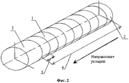
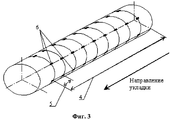
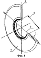
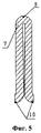
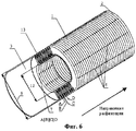
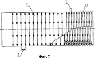
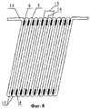
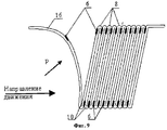
На фиг. 1 изображен развернутый по длине и периметру рукав; на фиг.2 - развернутый по длине и периметру рукав, разделенный на шаги; на фиг.3 - развернутый по длине и периметру рукав с установленными на нем фиксаторами; на фиг. 4 изображен элемент-складка, складываемый по периметру рукава; на фиг. 5 показано сечение элемента-складки; на фиг.6 изображен компактно уложенный в змейку эластичный рукав; на фиг.7 - рукав, складываемый в элементы-складки и далее в змейку; на фиг.8 - наклоненная змейка, пара элементов-складок и граница между ними; на фиг.9 - пошаговая расфиксация, пошаговое уплотнение и пошаговое послойное раскрытие элементов-складок рукава из положения змейки в начале движения. In FIG. 1 shows a sleeve deployed along the length and perimeter; figure 2 - deployed along the length and perimeter of the sleeve, divided into steps; figure 3 - deployed along the length and perimeter of the sleeve with the clips installed on it; in FIG. 4 shows a fold element folded along the perimeter of the sleeve; in FIG. 5 shows a section of a fold member; figure 6 shows an elastic sleeve compactly laid in a snake; in Fig.7 - a sleeve that folds into folds and then into a snake; on Fig - tilted snake, a pair of folds and the border between them; figure 9 - step-by-step unlocking, step-by-step sealing and step-by-step layer-by-layer opening of the folds of the sleeve from the position of the snake at the beginning of the movement.
Вначале развернутый по длине и периметру рукав 1 фиг.1 с его начала, от переднего края 2 к конечному краю укладки 3 на длине укладки 4 фиг.2 разделяют на шаги 5, на каждом шаге 5 создают условия для пошаговой фиксации и устанавливают, например, снаружи и изнутри фиксаторы 6 фиг.3. Initially deployed along the length and perimeter of the
Фиксаторы представляют собой различные виды элементов, способных при соприкосновении их поверхностей скрепляться друг с другом, как, например, элементы фиксации с использованием лейкопластыря, скотча, "липучки", некоторых видов клея, механических кнопок, магнитов, электромагнитов и других, а для расфиксации их необходимо прилагать определенные усилия. The latches are various types of elements that can be attached to each other when their surfaces are in contact, such as fixing elements using adhesive tape, adhesive tape, Velcro, some types of glue, mechanical buttons, magnets, electromagnets and others, and for fixing them some effort is needed.
Далее на каждом шаге 5 рукав 1 складывают по периметру в виде элемента-складки 7 фиг.4, 5 с вершиной 8, которую располагают по наружному диаметру 9 рукава, и двумя основаниями 10, каждое из которых соединяется с вершиной 8 своей стороной 11, и образуют внутренний диаметр 12 укладки рукава. Further, at each
Элементы-складки 7 последовательно фиксируют в вершинах 8 и сдвигают вплотную друг к другу каждую пару их оснований 10, сторон 11 и самих элементов-складок 7 в положение, приближающееся к параллельности их между собой с образованием из них змейки 13, фиг.6, 7. The
Каждый элемент-складку змейки 13 наклоняют основаниями 10 в направлении от переднего края 2 к конечному краю 3 укладки рукава, элементы-складки змейки последовательно фиксируют в вершинах 8, на каждом элементе-складке 7 змейки фиксируют основания 10 между собой. Each folding element of the
Укладываемый таким образом рукав 1 фиксируют в положении наклоненной 17 змейки фиг. 8 с параллельными между собой элементами-складками 7, с возможностью обеспечения на границе 14 каждой пары 15 элементов-складок 7 пошаговой последовательной расфиксации впереди идущего 16 фиг.9 элемента-складки, пошагового уплотнения последующего элемента-складки и пошагового послойного раскрытия впереди идущего 16 элемента-складки при переходе рукава от положения, уложенного в наклоненную змейку, до развернутого по длине и периметру. The
Пошаговая расфиксация впереди идущего 16 элемента-складки 7 начинается с расфиксации фиксатора 6 в направлении, противоположном движению. Step-by-step unlocking of the front-folding
Создают условия для пошаговой фиксации, при которых обеспечивают пошаговую расфиксацию и пошаговое послойное раскрытие элемента-складки 7 усилием от минимального до максимального в направлении от конечного края укладки 3 к переднему 2 путем изменения угла наклона элементов-складок 7 змейки в диапазоне 5÷86o.Create conditions for step-by-step fixation, under which step-by-step unlocking and step-by-step layer-by-layer opening of the
Создают дополнительные условия для пошаговой фиксации с возможностью обеспечения пошаговой расфиксации изменяемым по длине укладки 4 усилием от максимального до минимального в направлении от переднего края укладки 2 к конечному 3. Create additional conditions for step-by-step fixation with the possibility of providing step-by-step fixation with a force varying along the length of the
Расфиксируют элементы-складки 7 змейки 13 последовательно от фиксаторов 6, установленных в вершинах 8, к фиксаторам 6 в основаниях 10 элемента-складки и далее от фиксаторов 6 в основаниях 10 к фиксаторам 6 в вершинах 8 элементов-складок и так далее по всей змейке. Unfold the
Создают величину усилия расфиксации элемента-складки 7 по вершинам 8 и основаниям 10 равными. Create the value of the force of the fixation of the
Создают величину усилия расфиксации элемента-складки 7 по основаниям 10 меньше по своим значениям усилия расфиксации по вершинам 8. Create the value of the force of the fixation of the
Создают условия для обеспечения пошаговой расфиксации изменяемым на каждом шаге по длине укладки 4 усилием. They create conditions for providing step-by-step fixation with a force that is variable at each step along the laying
Создают условия для обеспечения пошаговой расфиксации изменяемым на нескольких шагах 5 по длине укладки 4 усилием. They create conditions for providing step-by-step fixation with a force that is variable at
Создают условия для обеспечения пошаговой расфиксации изменяемым кратно через несколько шагов по длине укладки 4 усилием. They create conditions for providing step-by-step fixation by a force that can be changed multiple times after several steps along the laying length.
Создают условия для обеспечения пошаговой расфиксации элементов-складок 7, изменяя усилие расфиксации путем изменения количества фиксаторов 6 по периметру элемента-складки 7. They create conditions for providing step-by-step unlocking of
Создают условия для обеспечения пошаговой расфиксации элементов-складок 7, изменяя усилие расфиксации путем изменения площади фиксации фиксаторов 6. They create conditions for providing step-by-step unlocking of
Создают условия для обеспечения пошаговой расфиксации элементов-складок 7, изменяя усилия расфиксации путем одновременного изменения количества фиксаторов по периметру и площади их фиксации. They create conditions for providing step-by-step unlocking of
Изобретение позволяет сделать упорядоченную укладку эластичной оболочки рукавного типа с возможностью проведения ее регламентированной раскладки, определения значений заданных параметров процесса в любом отрезке времени его протекания, например, усилия, давления, скорости, ускорения и других, что обеспечивает безаварийность, повышает безопасность, долговечность и надежность протекания процесса раскладки. EFFECT: invention makes it possible to make an orderly laying of a sleeve-type elastic shell with the possibility of carrying out its regulated layout, determining values of predetermined process parameters in any length of its flow time, for example, effort, pressure, speed, acceleration and others, which ensures trouble-free operation, increases safety, durability and reliability the course of the layout process.
Упорядоченная компактная укладка оболочки рукавного типа позволяет увеличить многократно радиус действия при ее раскладке, а также упростить и уменьшить конструкцию устройства и снизить его себестоимость. An ordered compact laying of the sleeve-type shell allows you to increase the radius of action many times during its layout, as well as simplify and reduce the design of the device and reduce its cost.
Claims (12)
Priority Applications (1)
| Application Number | Priority Date | Filing Date | Title |
|---|---|---|---|
| RU2002125487A RU2212373C1 (en) | 2002-09-25 | 2002-09-25 | Flexible hose stowing method |
Applications Claiming Priority (1)
| Application Number | Priority Date | Filing Date | Title |
|---|---|---|---|
| RU2002125487A RU2212373C1 (en) | 2002-09-25 | 2002-09-25 | Flexible hose stowing method |
Publications (1)
| Publication Number | Publication Date |
|---|---|
| RU2212373C1 true RU2212373C1 (en) | 2003-09-20 |
Family
ID=29777899
Family Applications (1)
| Application Number | Title | Priority Date | Filing Date |
|---|---|---|---|
| RU2002125487A RU2212373C1 (en) | 2002-09-25 | 2002-09-25 | Flexible hose stowing method |
Country Status (1)
| Country | Link |
|---|---|
| RU (1) | RU2212373C1 (en) |
Citations (4)
| Publication number | Priority date | Publication date | Assignee | Title |
|---|---|---|---|---|
| US3670763A (en) * | 1971-02-19 | 1972-06-20 | Gen Fire Extinguisher Corp | Semiautomatic hose rack |
| US3736952A (en) * | 1971-09-30 | 1973-06-05 | Elkhart Brass Manuf Co Inc | Fire hose rack |
| US3811633A (en) * | 1972-10-20 | 1974-05-21 | Rockwell International Corp | Tubular extendable structure |
| GB1537982A (en) * | 1976-04-19 | 1979-01-10 | Central Soya Co | Web dispenser |
-
2002
- 2002-09-25 RU RU2002125487A patent/RU2212373C1/en not_active IP Right Cessation
Patent Citations (4)
| Publication number | Priority date | Publication date | Assignee | Title |
|---|---|---|---|---|
| US3670763A (en) * | 1971-02-19 | 1972-06-20 | Gen Fire Extinguisher Corp | Semiautomatic hose rack |
| US3736952A (en) * | 1971-09-30 | 1973-06-05 | Elkhart Brass Manuf Co Inc | Fire hose rack |
| US3811633A (en) * | 1972-10-20 | 1974-05-21 | Rockwell International Corp | Tubular extendable structure |
| GB1537982A (en) * | 1976-04-19 | 1979-01-10 | Central Soya Co | Web dispenser |
Similar Documents
| Publication | Publication Date | Title |
|---|---|---|
| KR101933485B1 (en) | Automatic umbrella | |
| US9427876B2 (en) | Inflatable robots, robotic components and assemblies and methods including same | |
| CN105620779B (en) | Capture device for unmanned aerial vehicle including orbital capture cable and related systems and methods | |
| JP4993786B2 (en) | Gabion deployment | |
| CN209731322U (en) | A kind of Folding screen expanding unit and terminal | |
| US10118713B2 (en) | Electric unmanned aerial vehicle launcher | |
| US4555585A (en) | Foldable solar cell panel apparatus | |
| EP0067483B1 (en) | Method for unloading bulk freight from a cargo body or container as well as cargo body or container for carrying out the method | |
| US20150060600A1 (en) | Electric unmanned aerial vehicle launcher | |
| EP0108202A1 (en) | Transportation system utilizing a stretchable train of cars and stretchable bandconveyors | |
| AU2011203377A1 (en) | A pilot chute device | |
| RU2212373C1 (en) | Flexible hose stowing method | |
| CN101378978B (en) | Heavy object conveyance device | |
| JP7219229B2 (en) | Dunnage machine supply station and dunnage system | |
| RU2212372C1 (en) | Flexible hose stowing method | |
| EP4019400B1 (en) | Electric unmanned aerial vehicle launcher | |
| RU2212371C1 (en) | Flexible hose stowing method | |
| US5573295A (en) | Double pivot arm cover system | |
| US3391771A (en) | Tie-back assembly for aircraft escape slide | |
| ITMO990137A1 (en) | TOWER CAROUSEL FOR FUN. | |
| US10625870B1 (en) | Secured lines for ballistic recovery system | |
| RU2233787C2 (en) | Object displacement method | |
| RU2245295C2 (en) | Object displacement device | |
| US12540043B2 (en) | Ejection of items using an inflatable device with rolling convolutions | |
| RU2246442C2 (en) | Object displacement device |
Legal Events
| Date | Code | Title | Description |
|---|---|---|---|
| MM4A | The patent is invalid due to non-payment of fees |
Effective date: 20090926 |