RU2209333C2 - Conour of rocket nozzle to control division of flow and reduct side load - Google Patents
Conour of rocket nozzle to control division of flow and reduct side load Download PDFInfo
- Publication number
- RU2209333C2 RU2209333C2 RU2001114577/06A RU2001114577A RU2209333C2 RU 2209333 C2 RU2209333 C2 RU 2209333C2 RU 2001114577/06 A RU2001114577/06 A RU 2001114577/06A RU 2001114577 A RU2001114577 A RU 2001114577A RU 2209333 C2 RU2209333 C2 RU 2209333C2
- Authority
- RU
- Russia
- Prior art keywords
- profile
- nozzle
- derivative
- flow
- radius
- Prior art date
Links
Images
Classifications
-
- F—MECHANICAL ENGINEERING; LIGHTING; HEATING; WEAPONS; BLASTING
- F02—COMBUSTION ENGINES; HOT-GAS OR COMBUSTION-PRODUCT ENGINE PLANTS
- F02K—JET-PROPULSION PLANTS
- F02K9/00—Rocket-engine plants, i.e. plants carrying both fuel and oxidant therefor; Control thereof
- F02K9/97—Rocket nozzles
-
- F—MECHANICAL ENGINEERING; LIGHTING; HEATING; WEAPONS; BLASTING
- F05—INDEXING SCHEMES RELATING TO ENGINES OR PUMPS IN VARIOUS SUBCLASSES OF CLASSES F01-F04
- F05D—INDEXING SCHEME FOR ASPECTS RELATING TO NON-POSITIVE-DISPLACEMENT MACHINES OR ENGINES, GAS-TURBINES OR JET-PROPULSION PLANTS
- F05D2250/00—Geometry
- F05D2250/10—Two-dimensional
- F05D2250/16—Two-dimensional parabolic
Landscapes
- Engineering & Computer Science (AREA)
- Chemical & Material Sciences (AREA)
- Combustion & Propulsion (AREA)
- Mechanical Engineering (AREA)
- General Engineering & Computer Science (AREA)
- Jet Pumps And Other Pumps (AREA)
- Aerodynamic Tests, Hydrodynamic Tests, Wind Tunnels, And Water Tanks (AREA)
- Testing Of Engines (AREA)
- Control Of Turbines (AREA)
Abstract
Description
Изобретение относится к полнопоточному ракетному соплу, продольный контур которого, по существу, соответствует параболе. The invention relates to a full-flow rocket nozzle, the longitudinal contour of which essentially corresponds to a parabola.
Уровень техники
Функция ракетного сопла состоит в том, чтобы осуществлять расширение и ускорение газа до высокой скорости и тем самым обеспечивать эффективность тяги и грузоподъемность. Способность расширять поток газа ограничивается тем обстоятельством, что давление окружающей среды на уровне моря приводит к разделению потока. Разделенный поток генерирует нестабильные аэродинамические силы. Эти силы устанавливают предел для размеров сопла и тем самым ограничивают эффективность сопла при работе в вакууме. По теплотехническим соображениям сопла первой ступени могут работать, будучи разделенными в направлении выхода. Это означает, что если удастся снизить аэродинамические силы до приемлемого уровня, сопла могут работать в разделенном состоянии в непрерывном режиме как на уровне земли, так и при наборе высоты. Тем самым будет обеспечена возможность создания более крупных и более эффективных сопел.State of the art
The function of the rocket nozzle is to expand and accelerate the gas to a high speed and thereby ensure thrust efficiency and lifting capacity. The ability to expand the gas flow is limited by the fact that environmental pressure at sea level leads to a separation of the flow. The divided flow generates unstable aerodynamic forces. These forces set a limit on the size of the nozzle and thereby limit the efficiency of the nozzle when operating in a vacuum. For thermotechnical reasons, the nozzles of the first stage can work, being separated in the direction of exit. This means that if it is possible to reduce the aerodynamic forces to an acceptable level, the nozzles can operate in a divided state in continuous mode both at ground level and during climb. Thus, it will be possible to create larger and more efficient nozzles.
Обычно контур сопла соответствует непрерывному плавному профилю, оптимизированному для минимизации ухудшения характеристик при ударных нагрузках и расхождении потока. В типичном случае контур описывается параболической функцией. До настоящего времени контуры сопел не оптимизировались для работы с разделенным потоком на уровне моря, поскольку не было известно необходимых для этого средств управления боковой нагрузкой. Typically, the nozzle contour corresponds to a continuous smooth profile that is optimized to minimize degradation in shock and flow divergence. In a typical case, the contour is described by a parabolic function. To date, the nozzle circuits have not been optimized for operation with a split flow at sea level, since the necessary lateral load controls were not known for this.
Предпринимались попытки непрямых воздействий на контур сопла. Подобные предшествующие попытки включали, например, использование выходного диффузора (см. ЕР 626513 А1); перекидывающегося кольца; подвергающейся абляции или эжектируемой вставки; периодическое изменение радиуса (см. PCT/SE96/00176); сопла с прорезями (US 4947644); выходные эжекторные средства (ЕР 894031) и механизм выдвигаемой выходной части сопла (ЕР 924041). Устройство для управления разделением потока известно из документа US 3394549 А1. Attempts have been made to indirectly affect the nozzle circuit. Similar previous attempts included, for example, the use of an output diffuser (see EP 626513 A1); throwing ring; subject to ablation or ejected insert; periodically changing radius (see PCT / SE96 / 00176); slotted nozzles (US 4,947,644); output ejector means (EP 894031) and a mechanism for a retractable nozzle exit part (EP 924041). A device for controlling flow separation is known from US Pat. No. 3,394,549 A1.
Итак, известные сопла характеризуются ограниченным коэффициентом расширения, что ограничивает эффективность их работы. Указанная эффективность оптимизируется с учетом степени разделения потока и боковых нагрузок. So, the known nozzles are characterized by a limited coefficient of expansion, which limits the efficiency of their work. The indicated efficiency is optimized taking into account the degree of flow separation and lateral loads.
Все вышеперечисленные меры предназначены для использования в сочетании с параболическим контуром или контуром в форме колокола. Это приводит к появлению длинных и тяжелых сопел. С учетом увеличения веса чистый выигрыш оказывается весьма умеренным, причем для очень больших сопел он уменьшается еще больше. Сопло с профилем в форме колокола, оптимизированное в отношении своих рабочих показателей, характеризуется наличием у своего среза постоянного градиента давления как функции длины по оси. Однако подобная оптимизация вступает в противоречие с оптимизацией в отношении боковых нагрузок. Вес сопла оказывает негативное влияние на вес и сложность двигателя в целом, а также на структуру ракетной тяги. Размер сопла может оказаться несовместимым с пространственными ограничениями, свойственными испытательным установкам, ракетным системам и стартовым площадкам. All of the above measures are intended to be used in combination with a parabolic or bell-shaped circuit. This results in long and heavy nozzles. Given the increase in weight, the net gain is very moderate, and for very large nozzles it decreases even more. A nozzle with a bell-shaped profile, optimized for its performance, is characterized by the presence of a constant pressure gradient in its section as a function of axis length. However, such optimization conflicts with optimization regarding lateral loads. The weight of the nozzle negatively affects the weight and complexity of the engine as a whole, as well as the structure of the rocket thrust. The nozzle size may not be compatible with the spatial limitations inherent in test rigs, missile systems and launch sites.
Сущность изобретения
Таким образом, в соответствии с настоящим изобретением предлагается полнопоточное ракетное сопло, профиль которого в продольном сечении, по существу, соответствует параболе и которое обеспечивает устранение отмеченных недостатков, присущих известным из уровня техники полнопоточным соплам. Основная идея настоящего изобретения заключается в том, что эффективный параболический профиль сохраняется по всей длине той части сопла, давление в которой остается высоким и оказывает значительное влияние на результирующие характеристики. После этого предлагается использовать один из трех альтернативных профилей. Таким образом, основная отличительная особенность настоящего изобретения состоит в том, что, начиная от точки, соответствующей коэффициенту расширения, равному 50%, параболический контур сопла в направлении от его критического сечения (горловины) преобразуется в (1) строго конический профиль с углом при вершине между 15 и 25o, (2) криволинейный профиль с небольшой вогнутостью наружу, т.е. профиль, характеризующийся положительной второй производной радиуса r, или (3) криволинейный профиль с небольшой вогнутостью внутрь, т.е. профиль, характеризующийся отрицательной второй производной радиуса r, но лежащий снаружи параболического контура, причем в последнем варианте третья производная r постоянно равна нулю.SUMMARY OF THE INVENTION
Thus, in accordance with the present invention, there is provided a full-flow rocket nozzle, the profile of which in longitudinal section essentially corresponds to a parabola and which eliminates the noted drawbacks inherent in the full-flow nozzles known from the prior art. The main idea of the present invention is that an effective parabolic profile is maintained along the entire length of that part of the nozzle, the pressure in which remains high and has a significant effect on the resulting characteristics. After that, it is proposed to use one of the three alternative profiles. Thus, the main distinguishing feature of the present invention is that, starting from a point corresponding to an expansion coefficient of 50%, the parabolic contour of the nozzle in the direction from its critical section (neck) is converted into (1) a strictly conical profile with an angle at the apex between 15 and 25 o , (2) a curved profile with a slight concavity outward, i.e. a profile characterized by a positive second derivative of radius r, or (3) a curved profile with a slight concavity inward, i.e. a profile characterized by a negative second derivative of radius r, but lying outside the parabolic contour, and in the latter case, the third derivative r is constantly equal to zero.
В соответствии с изобретением площадь нижней части сопла при переходе к модифицированному профилю возрастает быстрее. Уровень давления в данной зоне ниже, и рабочие характеристики не испытывают резкого ухудшения. Интересно также уменьшить в этой зоне градиент давления как функцию длины сопла для того, чтобы уменьшить аэроупругое сопряжение. Эта задача также решается настоящим изобретением. In accordance with the invention, the area of the lower part of the nozzle when moving to a modified profile increases faster. The pressure level in this area is lower, and the performance does not experience sharp deterioration. It is also interesting to reduce the pressure gradient in this zone as a function of nozzle length in order to reduce aeroelastic coupling. This problem is also solved by the present invention.
В качестве предпочтительного варианта выполнения сопла по изобретению предусматривается, что в переходной зоне от параболического контура в контуре имеется скачок, выбранный в интервале от 0 до 6o. Более резкое (скачкообразное) расширение сопла на начальном участке расширения вносит дополнительный вклад в сокращение общей длины сопла.As a preferred embodiment of the nozzle according to the invention, it is provided that in the transition zone from the parabolic circuit in the circuit there is a jump selected in the range from 0 to 6 o . A sharper (spasmodic) expansion of the nozzle in the initial expansion section makes an additional contribution to reducing the total length of the nozzle.
При использовании изобретения могут быть разработаны сопла с профилями, существенно отличными от известных. Изобретение позволяет применять более крупные сопла на уровне моря, обеспечивая тем самым повышенную грузоподъемность. Далее, изобретение минимизирует длину и, следовательно, уменьшает вес сопла, а также момент боковой нагрузки, создаваемый механическими силами в сопле увеличенного размера по сравнению с соплами обычных размеров. Изобретение обеспечивает увеличение производной давления как функции длины сопла в той зоне по оси сопла, где действуют значительные боковые нагрузки, что способствует снижению этих нагрузок. Наконец, изобретение улучшает возможности пленочного охлаждения, поскольку длина пленки сокращена по сравнению с соплами увеличенных размеров и с контуром в форме колокола. When using the invention, nozzles with profiles substantially different from the known ones can be developed. The invention allows the use of larger nozzles at sea level, thereby providing increased carrying capacity. Further, the invention minimizes the length and, consequently, reduces the weight of the nozzle, as well as the moment of lateral load created by mechanical forces in the oversized nozzle in comparison with nozzles of conventional sizes. The invention provides an increase in the derivative of pressure as a function of the length of the nozzle in that area along the axis of the nozzle where significant lateral loads act, which helps to reduce these loads. Finally, the invention improves film cooling capabilities since the film length is reduced compared to oversized nozzles and with a bell-shaped contour.
Сама по себе оптимизация профиля может не обеспечить удовлетворения требований, определяющих возможность непрерывной работы сопел в режиме разделения потоков на уровне моря. Тем не менее, улучшаются условия для выполнения этих требований при разделении потока. Optimization of the profile itself may not ensure the satisfaction of requirements that determine the possibility of continuous operation of nozzles in the mode of separation of flows at sea level. Nonetheless, the conditions for fulfilling these requirements while splitting the stream are improved.
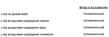
Для типичного сопла первой ступени, модифицированного с целью использования преимуществ разделенного потока, примерная структура выигрыша может в принципе быть проиллюстрирована приводимой далее таблицей. Таблица охватывает три предлагаемых контура. Сравнение проводится для сопла первой ступени, модифицированного для получения коэффициента площади на выходе, равного 170%. Все вклады в рабочие характеристики были пересчитаны для конкретного импульса с использованием приближенных коэффициентов, соответствующих ракете Vulcain 5. For a typical first stage nozzle, modified to take advantage of the split flow, an exemplary gain structure can, in principle, be illustrated in the table below. The table covers the three proposed contours. The comparison is carried out for the nozzle of the first stage, modified to obtain a coefficient of the area at the exit equal to 170%. All performance contributions were recalculated for a specific impulse using approximate coefficients corresponding to the Vulcain 5 rocket.
Удельный импульс Isp (удельная тяга) на уровне моря возрастает благодаря тому, что давление в разделенной зоне возрастает в связи с расширением зоны рециркуляции. Возрастание удельного импульса на уровне моря может быть пересчитано в небольшое увеличение Isp в вакууме. The specific impulse Isp (specific thrust) at sea level increases due to the fact that the pressure in the divided zone increases due to the expansion of the recirculation zone. An increase in the specific momentum at sea level can be converted into a small increase in Isp in vacuum.
Площадь смачивания поверхности сопла сокращается. В результате уменьшатся потери на трение, что даст положительный вклад в Isp в вакууме. The wetting area of the nozzle surface is reduced. As a result, friction losses will be reduced, which will make a positive contribution to Isp in a vacuum.
В результате уменьшения длины сопла уменьшится и вес двигателя. Уменьшение веса может быть пересчитано в прирост Isp в вакууме. As a result of reducing the length of the nozzle, the weight of the engine will also decrease. Weight reduction can be converted to Isp gain in vacuum.
Снижение стоимости двигателя также может быть пересчитано в прирост Isp в вакууме. The reduction in engine cost can also be converted to an increase in Isp in vacuum.
При этом можно допустить наличие негативного вклада в Isp в вакууме (из-за потерь вследствие расходимости) в пределах суммы положительных вкладов, т. е. при сохранении показателей затраты-эффективность, с точки зрения рабочих характеристик, для ракеты по сравнению с идеальным контуром. In this case, it is possible to admit the presence of a negative contribution to Isp in a vacuum (due to losses due to divergence) within the sum of positive contributions, i.e., while maintaining the cost-effectiveness indicators, from the point of view of performance, for a rocket compared to the ideal contour.
Согласно изобретению плечо момента боковой нагрузки сокращается на величину порядка 20%. Можно ожидать, что боковая нагрузка изменится примерно на эту величину. Боковая нагрузка уменьшится также вследствие положительного эффекта от увеличения градиента аксиального давления на выходе. According to the invention, the shoulder moment of the lateral load is reduced by about 20%. It can be expected that the lateral load will change by approximately this value. The lateral load will also decrease due to the positive effect of an increase in the axial pressure gradient at the outlet.
Все предлагаемые профили обеспечивают более быстрое расширение газа с меньшим восстановлением давления на выходе из сопла. Это означает, что тепловая нагрузка снижается. Данное обстоятельство может стать очень важным при оснащении существующих сопел модифицирующими комплектами. All of the proposed profiles provide faster gas expansion with less pressure recovery at the nozzle exit. This means that the heat load is reduced. This circumstance can become very important when equipping existing nozzles with modifying kits.
Перечень фигур чертежей
Далее настоящее изобретение будет более подробно описано со ссылками на прилагаемые чертежи.List of drawings
The present invention will now be described in more detail with reference to the accompanying drawings.
Фиг. 1 схематично иллюстрирует усеченное сопло в форме колокола с добавленной к нему конической частью. FIG. 1 schematically illustrates a truncated bell-shaped nozzle with a conical portion added thereto.
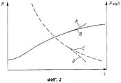
Фиг. 2 схематично иллюстрирует усеченное сопло в форме колокола с добавленной к нему частью, для которой вторая производная радиуса по длине положительна. FIG. 2 schematically illustrates a truncated bell-shaped nozzle with a portion added to it for which the second derivative of the radius radius is positive in length.
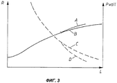
Фиг. 3 схематично иллюстрирует усеченное сопло в форме колокола с добавленной к нему частью, для которой вторая производная радиуса по длине отрицательна, но третья производная радиуса постоянна и равна нулю. FIG. 3 schematically illustrates a truncated bell-shaped nozzle with a portion added to it for which the second derivative of the radius is negative in length, but the third derivative of the radius is constant and equal to zero.
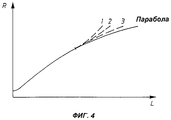
На фиг.4 представлены результаты сравнения известных профилей и профилей по изобретению. Figure 4 presents the results of a comparison of known profiles and profiles according to the invention.
Сведения, подтверждающие возможность осуществления изобретения
На фиг.1-3 через А обозначен модифицированный профиль сопла; В - это базовый радиус; С - базовое давление; D - модифицированное давление.Information confirming the possibility of carrying out the invention
1-3 through A denotes a modified nozzle profile; B is the base radius; C is the base pressure; D is the modified pressure.
Обычная практика состоит в выборе параболического профиля ракетного сопла с использованием профилей, имеющих отрицательную вторую производную радиуса по длине. В отличие от профилей этого типа, коническое сопло представляет собой специальный случай с постоянной производной. В связи с этим обсуждение конического профиля вполне уместно в рамках данной заявки. Потери в Isp могут быть меньше, поскольку появляется возможность дольше сохранять эффективный колоколообразный профиль и тем не менее обеспечить желаемое соотношение для выходной зоны. A common practice is to select the parabolic profile of the rocket nozzle using profiles having a negative second derivative of the radius in length. Unlike profiles of this type, a conical nozzle is a special case with a constant derivative. In this regard, the discussion of the conical profile is quite appropriate in the framework of this application. Losses in Isp can be less, since it becomes possible to maintain an effective bell-shaped profile longer and still provide the desired ratio for the exit zone.
Аналогичным образом, как это показано на фиг.3, профиль выбирается таким образом, чтобы вторая производная радиуса по длине была отрицательна, но третья производная радиуса (эквивалентная второй производной угла между касательной к контуру сопла и его продольной осью) была постоянна и равна нулю. Similarly, as shown in FIG. 3, the profile is selected so that the second derivative of the radius along the length is negative, but the third derivative of the radius (equivalent to the second derivative of the angle between the tangent to the nozzle contour and its longitudinal axis) is constant and equal to zero.
На фиг.4 профили, приведенные на фиг.1-3, представлены на едином графике, чтобы облегчить их сравнение. In Fig. 4, the profiles shown in Figs. 1-3 are presented in a single graph to facilitate comparison.
Для обеспечения сокращения длины сопла по изобретению в некоторых вариантах его выполнения целесообразно предусмотреть также более быстрое расширение сопла в переходной зоне от параболического контура, т.е. скачок на профиле, выбранный в интервале от 0 до 6o.In order to reduce the length of the nozzle according to the invention, in some embodiments, it is also advisable to provide a more rapid expansion of the nozzle in the transition zone from the parabolic circuit, i.e. a jump on the profile, selected in the range from 0 to 6 o .
Claims (2)
Applications Claiming Priority (1)
| Application Number | Priority Date | Filing Date | Title |
|---|---|---|---|
| PCT/SE1998/002222 WO2000034641A1 (en) | 1998-12-04 | 1998-12-04 | Rocket nozzle contour for flow separation control and side load reduction |
Publications (2)
| Publication Number | Publication Date |
|---|---|
| RU2001114577A RU2001114577A (en) | 2003-02-20 |
| RU2209333C2 true RU2209333C2 (en) | 2003-07-27 |
Family
ID=20411802
Family Applications (1)
| Application Number | Title | Priority Date | Filing Date |
|---|---|---|---|
| RU2001114577/06A RU2209333C2 (en) | 1998-12-04 | 1998-12-04 | Conour of rocket nozzle to control division of flow and reduct side load |
Country Status (7)
| Country | Link |
|---|---|
| US (1) | US6574964B1 (en) |
| EP (1) | EP1135588A1 (en) |
| JP (1) | JP2002531766A (en) |
| CN (1) | CN1322275A (en) |
| RU (1) | RU2209333C2 (en) |
| UA (1) | UA46175C2 (en) |
| WO (1) | WO2000034641A1 (en) |
Cited By (2)
| Publication number | Priority date | Publication date | Assignee | Title |
|---|---|---|---|---|
| EA008728B1 (en) * | 2005-02-22 | 2007-08-31 | Ажанс Спасьяль Эропеен | Device and method for reducing the nonsteady side loads acting on a nozzle of a rocket engine |
| RU2552020C2 (en) * | 2013-09-23 | 2015-06-10 | Государственный научный центр Российской Федерации-федеральное государственное унитарное предприятие "Исследовательский Центр имени М.В. Келдыша" | Rocket engine nozzle |
Families Citing this family (7)
| Publication number | Priority date | Publication date | Assignee | Title |
|---|---|---|---|---|
| US20080264372A1 (en) * | 2007-03-19 | 2008-10-30 | Sisk David B | Two-stage ignition system |
| DE102010042890B4 (en) | 2010-10-25 | 2020-07-30 | Deutsches Zentrum für Luft- und Raumfahrt e.V. | Engine device for a missile, test bench or launch pad for a missile and method for reducing a side load in an engine device |
| AT511466B1 (en) | 2011-08-03 | 2012-12-15 | Hoerbiger Kompressortech Hold | FLUID MIXER |
| US9009966B2 (en) * | 2013-03-15 | 2015-04-21 | Northrop Gurmman Systems Corporation | Internal/external single expansion ramp nozzle with integrated third stream |
| RU2531161C1 (en) * | 2013-04-24 | 2014-10-20 | Федеральное государственное унитарное предприятие "Центральный аэрогидродинамический институт имени профессора Н.Е. Жуковского" (ФГУП "ЦАГИ") | Axisymmetric nozzle of rocket engine |
| DE102015011958B4 (en) | 2015-09-18 | 2024-02-01 | Arianegroup Gmbh | Thruster |
| KR20200114123A (en) | 2019-03-27 | 2020-10-07 | 엘지전자 주식회사 | An air conditioning apparatus |
Family Cites Families (11)
| Publication number | Priority date | Publication date | Assignee | Title |
|---|---|---|---|---|
| US3352495A (en) * | 1965-01-29 | 1967-11-14 | Thiokol Chemical Corp | Nozzle construction |
| US3394549A (en) * | 1965-07-06 | 1968-07-30 | North American Rockwell | Step nozzle |
| FR2602275B1 (en) * | 1986-08-04 | 1990-08-10 | Onera (Off Nat Aerospatiale) | IMPROVEMENTS ON PROPELLER NOZZLES FOR REDUCING SIDE EFFORT |
| FR2618488B1 (en) | 1987-07-20 | 1989-12-15 | Europ Propulsion | DIVERGENT WITH BREAKING GALBE FOR NOZZLE OF MOTOR-ROCKET |
| US6324833B1 (en) * | 1990-04-24 | 2001-12-04 | Cordant Technologies, Inc. | Reinforced composite articles and method of making same |
| FR2705737B1 (en) | 1993-05-28 | 1995-08-18 | Europ Propulsion | Scalloped rocket engine nozzle. |
| FR2705739B1 (en) | 1993-05-28 | 1995-08-18 | Europ Propulsion | Rocket engine nozzle with selectively reduced outlet section. |
| WO1997029277A1 (en) * | 1996-02-12 | 1997-08-14 | Volvo Aero Corporation | Rocket engine nozzle |
| NL1004193C2 (en) | 1996-04-01 | 1997-10-02 | Sjoerd Meijer | Method for processing metal sheet. |
| WO1998012429A1 (en) * | 1996-09-23 | 1998-03-26 | Volvo Aero Corporation | Controlled temperature rocket nozzle |
| DE19755732C2 (en) | 1997-12-15 | 2000-01-13 | Waeschle Gmbh | Process for the production of granules from polymeric materials |
-
1998
- 1998-12-04 EP EP98965318A patent/EP1135588A1/en not_active Ceased
- 1998-12-04 WO PCT/SE1998/002222 patent/WO2000034641A1/en not_active Application Discontinuation
- 1998-12-04 UA UA2001063740A patent/UA46175C2/en unknown
- 1998-12-04 JP JP2000587065A patent/JP2002531766A/en active Pending
- 1998-12-04 CN CN98814321A patent/CN1322275A/en active Pending
- 1998-12-04 RU RU2001114577/06A patent/RU2209333C2/en not_active IP Right Cessation
- 1998-12-04 US US09/856,610 patent/US6574964B1/en not_active Expired - Fee Related
Cited By (2)
| Publication number | Priority date | Publication date | Assignee | Title |
|---|---|---|---|---|
| EA008728B1 (en) * | 2005-02-22 | 2007-08-31 | Ажанс Спасьяль Эропеен | Device and method for reducing the nonsteady side loads acting on a nozzle of a rocket engine |
| RU2552020C2 (en) * | 2013-09-23 | 2015-06-10 | Государственный научный центр Российской Федерации-федеральное государственное унитарное предприятие "Исследовательский Центр имени М.В. Келдыша" | Rocket engine nozzle |
Also Published As
| Publication number | Publication date |
|---|---|
| EP1135588A1 (en) | 2001-09-26 |
| WO2000034641A1 (en) | 2000-06-15 |
| JP2002531766A (en) | 2002-09-24 |
| CN1322275A (en) | 2001-11-14 |
| US6574964B1 (en) | 2003-06-10 |
| UA46175C2 (en) | 2002-05-15 |
Similar Documents
| Publication | Publication Date | Title |
|---|---|---|
| RU2209333C2 (en) | Conour of rocket nozzle to control division of flow and reduct side load | |
| US6568172B2 (en) | Converging nozzle thrust reverser | |
| US5000399A (en) | Variable contour annular air inlet for an aircraft engine nacelle | |
| US6546715B1 (en) | Cascade-type thrust reverser | |
| US7997872B2 (en) | Fan blade | |
| RU2331776C2 (en) | High area ratio autosuction interturbine duct assembly for gas turbine engine (versions), system and method of optimising efficiency of gas turbine engine incorporating suchduct | |
| US6419446B1 (en) | Apparatus and method for inhibiting radial transfer of core gas flow within a core gas flow path of a gas turbine engine | |
| US8662417B2 (en) | Gas turbine engine fan variable area nozzle with swivable insert system | |
| CA2935758C (en) | Integrated strut-vane nozzle (isv) with uneven vane axial chords | |
| US6260794B1 (en) | Dolphin cascade vane | |
| US6997676B2 (en) | Bifurcated outlet guide vanes | |
| US20090126339A1 (en) | Thrust Reverser Door | |
| JP2004084669A (en) | System and method for actively changing effective flow-through area of intake part region of aircraft engine | |
| EP2791477A2 (en) | Gas turbine engine exhaust diffuser including circumferential vane | |
| FR2463859A1 (en) | EJECTION TUBE WITH EJECTABLE GAS STREAM | |
| US20210301761A1 (en) | Variable area nozzle exhaust system with integrated thrust reverser | |
| US5038559A (en) | Method and apparatus for selectively varying an effective fluid flow area of a jet engine exhaust nozzle | |
| US6422820B1 (en) | Corner tang fan blade | |
| US5235808A (en) | Exhaust nozzle including idle thrust spoiling | |
| EP3702603A1 (en) | Thrust reverser assembly for an engine nacelle of an aircraft | |
| US7287369B2 (en) | Method for extending a nozzle and extended nozzle for rocket drives | |
| JPH07102903A (en) | Stress reduction type impeller blade | |
| RU2165538C2 (en) | Jet engine nozzle | |
| RU2454354C2 (en) | Supersonic aircraft jet engine | |
| WO1996034193A1 (en) | Thrust reverser mechanism for reducing fan distortion |
Legal Events
| Date | Code | Title | Description |
|---|---|---|---|
| MM4A | The patent is invalid due to non-payment of fees |
Effective date: 20081205 |