RU2205259C2 - Device for control of water level in hydraulic structures - Google Patents
Device for control of water level in hydraulic structures Download PDFInfo
- Publication number
- RU2205259C2 RU2205259C2 RU2001121043/13A RU2001121043A RU2205259C2 RU 2205259 C2 RU2205259 C2 RU 2205259C2 RU 2001121043/13 A RU2001121043/13 A RU 2001121043/13A RU 2001121043 A RU2001121043 A RU 2001121043A RU 2205259 C2 RU2205259 C2 RU 2205259C2
- Authority
- RU
- Russia
- Prior art keywords
- water
- gate
- drum
- water level
- horizontal axis
- Prior art date
Links
Images
Landscapes
- Barrages (AREA)
Abstract
Description
Изобретение относится к гидротехнике и может быть использовано для регулирования уровней воды в оросительных каналах. The invention relates to hydraulic engineering and can be used to control water levels in irrigation canals.
Известны устройства для регулирования уровней воды в гидротехнических сооружениях, включающие водоизмещающий затвор, горизонтальную ось вращения и калиброванные отверстия для воды и воздуха (Авторское свидетельство СССР 589327, МКИ Е 02 В 13/00, 1978). Known devices for regulating water levels in hydraulic structures, including a displacement shutter, a horizontal axis of rotation and calibrated holes for water and air (USSR Author's Certificate 589327, MKI E 02 B 13/00, 1978).
Однако известные водоизмещающие затворы сложны конструктивно и регулируют уровень при пропуске воды в одном направлении. However, the known displacement gates are structurally complex and regulate the level when passing water in one direction.
В предлагаемом устройстве, включающем водоизмещающий затвор, горизонтальную ось вращения и калиброванные отверстия для воды и воздуха, водоизмещающий затвор выполнен в виде барабана с лопастями, калиброванные отверстия для воды и воздуха выполнены на образующей поверхности барабана противоположно друг другу, а горизонтальная ось вращения своими концами закреплена в направляющих с возможностью свободного перемещения в вертикальной плоскости. In the proposed device, which includes a displacement shutter, a horizontal axis of rotation and calibrated holes for water and air, a displacement shutter is made in the form of a drum with blades, calibrated holes for water and air are made on the forming surface of the drum opposite each other, and the horizontal axis of rotation is fixed at its ends in guides with the possibility of free movement in a vertical plane.
Кроме этого, горизонтальная ось вращения связана со счетчиком расхода воды. In addition, the horizontal axis of rotation is associated with a water flow meter.
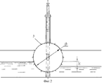
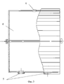
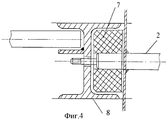
На фиг.1 изображен поперечный разрез оросительного канала с предлагаемым устройством для регулирования уровней воды в оросительном канале, на фиг.2 - он же, продольный разрез, на фиг.3 - конструктивная схема водоизмещающего затвора, на фиг.4 - вид А на фиг.1. Figure 1 shows a cross section of an irrigation canal with the proposed device for regulating water levels in an irrigation canal, Fig.2 is a longitudinal section, Fig.3 is a structural diagram of a displacement shutter, Fig.4 is a view A in Fig. .1.
Предлагаемое устройство включает водоизмещающий затвор 1, горизонтальную ось вращения 2. Затвор 1 выполнен в виде барабана с лопастями 3, внутренняя полость 4 которого снабжена калиброванными отверстиями 5 и 6, расположенными на образующей поверхности барабана противоположно друг другу. Горизонтальная ось вращения закреплена в направляющих 7 и 8 с возможностью свободного перемещения в вертикальной плоскости и может быть связана со счетчиком расхода воды 9. Кроме этого, устройство может быть снабжено грузоподъемным винтовым механизмом 10. The proposed device includes a displacement shutter 1, the horizontal axis of
Работает устройство следующим образом. The device operates as follows.
Водоизмещающий затвор 1 вращается на горизонтальной оси 2 с помощью лопастей 3 в сторону забора воды, при этом горизонтальная ось 2 свободно перемещается в вертикальной плоскости в направляющих 7 и 8. При вращении барабана калиброванные отверстия 5 и 6 поочередно погружаются в воду или сообщаются с атмосферой. При заборе воды в канале образуется перепад уровней воды "Z" до затвора и после него. Поэтому при погружении калиброванных отверстий 5 в воду вода из верхнего бьефа заполняет внутреннюю полость 4 барабана, так как в это время другие калиброванные отверстия 6 сообщаются с атмосферой. Когда отверстия 5 попадут в нижний бьеф, происходит опорожнение полости 4 и замещение воды воздухом через отверстия 6. Отверстия 5 и 6 калибруются так, чтобы поддерживать заданный перепад уровней воды Н при соответствующем расходе воды из канала. Поэтому, если изменяется перепад уровней в ту или другую сторону, происходит заполнение или опорожнение внутренней полости 4 вращающегося затвора. В результате чего затвор 1 перемещается по направляющим 7 и 8 вниз или вверх, увеличивая или уменьшая проходное сечение для пропуска воды. При прекращении забора воды исчезает перепад уровней воды в канале. В этом случае внутренняя полость 4 затвора 1 заполняется водой до максимального объема. Затвор 1 полностью погружается в воду, изменив проходное сечение для пропуска минимального объема воды. The displacement shutter 1 rotates on the
По количеству совершенных оборотов затвора во время пропуска воды можно вести учет расхода воды на каждом участке канала. Для этого горизонтальная ось вращения 2 связана со счетчиком расхода воды 9. By the number of perfect shutter revolutions during the passage of water, it is possible to keep track of the water flow in each section of the channel. For this, the horizontal axis of
Когда забор воды осуществляют из участка канала до затвора, также возникнет перепад уровней воды Н. В результате затвор 1 будет вращаться в обратную сторону, пропуская воду из нижнего участка канала в верхний. Это позволяет не сбрасывать воду из нижнего участка канала, а использовать ее для полива и тем самым сократить расход воды, используемый при поливе. Винтовой механизм 10 используется для подъема барабана при его техническом обслуживании и ремонте. When water is taken from the channel section to the gate, a difference in water levels N will also occur. As a result, the gate 1 will rotate in the opposite direction, passing water from the lower section of the channel to the upper. This allows not to discharge water from the lower part of the canal, but to use it for irrigation and thereby reduce the water flow used during irrigation. The screw mechanism 10 is used to lift the drum during its maintenance and repair.
Claims (2)
Priority Applications (1)
| Application Number | Priority Date | Filing Date | Title |
|---|---|---|---|
| RU2001121043/13A RU2205259C2 (en) | 2001-07-26 | 2001-07-26 | Device for control of water level in hydraulic structures |
Applications Claiming Priority (1)
| Application Number | Priority Date | Filing Date | Title |
|---|---|---|---|
| RU2001121043/13A RU2205259C2 (en) | 2001-07-26 | 2001-07-26 | Device for control of water level in hydraulic structures |
Publications (2)
| Publication Number | Publication Date |
|---|---|
| RU2205259C2 true RU2205259C2 (en) | 2003-05-27 |
| RU2001121043A RU2001121043A (en) | 2003-06-20 |
Family
ID=20252125
Family Applications (1)
| Application Number | Title | Priority Date | Filing Date |
|---|---|---|---|
| RU2001121043/13A RU2205259C2 (en) | 2001-07-26 | 2001-07-26 | Device for control of water level in hydraulic structures |
Country Status (1)
| Country | Link |
|---|---|
| RU (1) | RU2205259C2 (en) |
Citations (3)
| Publication number | Priority date | Publication date | Assignee | Title |
|---|---|---|---|---|
| FR2548706A1 (en) * | 1983-07-04 | 1985-01-11 | Alsthom Atlantique | ROTATING VALVE |
| US4522534A (en) * | 1983-02-23 | 1985-06-11 | Hitachi, Ltd. | Control method for open channel |
| SU1500729A1 (en) * | 1987-07-27 | 1989-08-15 | Kirgiz Selskokhoz I | Hydraulic structure |
-
2001
- 2001-07-26 RU RU2001121043/13A patent/RU2205259C2/en not_active IP Right Cessation
Patent Citations (3)
| Publication number | Priority date | Publication date | Assignee | Title |
|---|---|---|---|---|
| US4522534A (en) * | 1983-02-23 | 1985-06-11 | Hitachi, Ltd. | Control method for open channel |
| FR2548706A1 (en) * | 1983-07-04 | 1985-01-11 | Alsthom Atlantique | ROTATING VALVE |
| SU1500729A1 (en) * | 1987-07-27 | 1989-08-15 | Kirgiz Selskokhoz I | Hydraulic structure |
Similar Documents
| Publication | Publication Date | Title |
|---|---|---|
| JPS59196978A (en) | Water engine | |
| RU2205259C2 (en) | Device for control of water level in hydraulic structures | |
| CN117403587A (en) | Staggered layout structure suitable for high-density urban river surge high and low water levels | |
| KR100592975B1 (en) | Adobe Block | |
| KR101405096B1 (en) | Oil pressure type movable that under low water is discharged | |
| CN206521736U (en) | Upper-turn-type gate | |
| CN204345043U (en) | A kind of float-ball type level control valve | |
| KR200338295Y1 (en) | A auto floodgate of dam with fishway | |
| JP4369687B2 (en) | Water weight type automatic water level control gate | |
| KR20120040301A (en) | Rotary-type floodgate | |
| JP2514866B2 (en) | Flow response gate for irrigation canal | |
| KR200244423Y1 (en) | Closed water gate operated by the water stop device | |
| JPH0340900Y2 (en) | ||
| JPS6032196Y2 (en) | undulating fishway gate device | |
| CN204982810U (en) | Automatic measure hollow gate of water intaking | |
| KR100781717B1 (en) | Adobe Block | |
| SU911478A1 (en) | Regulator of head water level in hydraulic structures | |
| US1695733A (en) | System for developing power from tides | |
| JP3528135B2 (en) | Reciprocating rocking device | |
| JP4449877B2 (en) | Scum removing device and method | |
| RU2743585C1 (en) | Water shutter | |
| JP2818969B2 (en) | Parallel fishway device | |
| SU1500729A1 (en) | Hydraulic structure | |
| RU2201487C2 (en) | Hydraulic autoregulator | |
| JPS6019142Y2 (en) | Fishway gate device |
Legal Events
| Date | Code | Title | Description |
|---|---|---|---|
| MM4A | The patent is invalid due to non-payment of fees |
Effective date: 20090727 |