RU2201901C1 - Water cleaning unit - Google Patents
Water cleaning unit Download PDFInfo
- Publication number
- RU2201901C1 RU2201901C1 RU2001135234A RU2001135234A RU2201901C1 RU 2201901 C1 RU2201901 C1 RU 2201901C1 RU 2001135234 A RU2001135234 A RU 2001135234A RU 2001135234 A RU2001135234 A RU 2001135234A RU 2201901 C1 RU2201901 C1 RU 2201901C1
- Authority
- RU
- Russia
- Prior art keywords
- water
- housing
- water flow
- supply pipe
- flow switch
- Prior art date
Links
Images
Abstract
Description
Изобретение относится к области очистки воды с помощью фильтрации от находящихся в ней примесей металлов, коллоидных и дисперсных частиц, бактерий и вирусов. The invention relates to the field of water purification by filtering from impurities of metals, colloidal and dispersed particles, bacteria and viruses.
Существует множество устройств для очистки воды, представляющих собой фильтры с загрузкой фильтрующего материала в корпусе устройства с подводящими и отводящими патрубками. Поток фильтруемой воды подается либо сверху вниз, в этом случае фильтрующая насадка прижимается к нижней дренажной системе, либо снизу вверх, в этом случае образуется взвешенный слой фильтрующего материала (Справочник химика-энергетика. - М.: Энергия, 1972, с. 149-153, Кастальский А.А., Минц Д.М. Подготовка воды для питьевого и промышленного водоснабжения. Госиздат "Высшая школа". - Москва, 1962 г., с. 500-507). There are many devices for water purification, which are filters with the loading of filter material in the device casing with inlet and outlet pipes. The stream of filtered water is supplied either from top to bottom, in this case, the filter nozzle is pressed to the lower drainage system, or from bottom to top, in this case a suspended layer of filter material is formed (Chemical-Energy Handbook. - M .: Energy, 1972, p. 149-153. , Kastalsky A.A., Mints D.M. Water Treatment for Drinking and Industrial Water Supply, State Publishing House "Higher School". - Moscow, 1962, p. 500-507).
Наиболее близким к заявленному является устройство для очистки воды от железа, содержащее корпус, расположенные в нем слои из фильтрующего материала, подводящий трубопровод, нижнее дренажное устройство для подачи воздуха и трубопроводы очистки и регенерации, соединенные между собой переключающей арматурой (см. патент РФ 2134660, опубл. 20.08.99). Closest to the claimed is a device for water purification from iron, containing a housing, layers of filtering material located in it, a supply pipe, a lower drainage device for air supply and cleaning and regeneration pipelines connected by switching valves (see RF patent 2134660, publ. 08.20.99).
К недостаткам этого устройства относится возможность выброса фильтрующего материала из корпуса при взрыхлении потоком воды, направляемой снизу вверх. Такая конструкция исключает применение в устройстве комбинаций фильтрующих материалов с различным удельным весом, например ионообменных смол, кварцевого песка, активированного угля. Другим недостатком является то, что взрыхление осуществляется потоком воды, это не обеспечивает глубокую отмывку фильтрующего материала и требует повышенного расхода воды. The disadvantages of this device include the possibility of ejection of filter material from the housing when loosening a stream of water directed from the bottom up. This design eliminates the use in the device of combinations of filter materials with different specific gravities, for example, ion-exchange resins, silica sand, activated carbon. Another disadvantage is that loosening is carried out by a stream of water, this does not provide deep washing of the filter material and requires an increased flow of water.
Задачей, на решение которой направлено изобретение, является расширение функциональных возможностей устройства за счет установки различных видов фильтрующих материалов, а также повышение экономичности за счет снижения себестоимости очистки воды. The problem to which the invention is directed, is to expand the functionality of the device by installing various types of filter materials, as well as increasing efficiency by reducing the cost of water treatment.
Поставленная задача решается тем, что устройство для очистки воды, содержащее корпус с расположенными в нем слоями фильтрующего материала, подводящий трубопровод, нижнее дренажное устройство, устройство для подачи воздуха и установленные снаружи корпуса трубопроводы очистки воды и регенерации, присоединенные соответственно к верхней и нижней частям корпуса и соединенные между собой и подводящим трубопроводом посредством переключателя потока воды, снабжено слоем катализатора, способствующего образованию дисперсных частиц из соединений металлов, содержащихся в очищаемой воде, устройство для подачи воздуха установлено на подводящем трубопроводе до переключателя потока воды, и над слоем катализатора установлено верхнее дренажное устройство. The problem is solved in that a water purification device comprising a housing with layers of filter material located therein, a supply pipe, a lower drainage device, an air supply device and water purification and regeneration pipelines installed outside the housing, connected respectively to the upper and lower parts of the housing and connected to each other and the supply pipe by means of a water flow switch, provided with a catalyst layer that promotes the formation of dispersed particles from the Nij metals contained in the feed water, the air supply device is installed on the supply line to water flow switch, and over the catalyst bed is set upper drainage device.
Фильтрующие слои могут быть выполнены из ионообменной смолы и, например, кварцевого песка. Устройство для подачи воздуха может быть выполнено в виде эжектора, а переключатель потока воды - в виде трехходового крана. The filter layers can be made of ion exchange resin and, for example, silica sand. The device for supplying air can be made in the form of an ejector, and the water flow switch is in the form of a three-way valve.
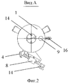
На фиг.1 представлен общий вид устройства, на фиг.2 - вид "А" на фиг.1. Figure 1 presents a General view of the device, figure 2 is a view of "A" in figure 1.
Устройство состоит из корпуса 1, верхнего дренажного устройства 2, подводящего трубопровода 3, переключателя 4 потока воды, нижнего дренажного устройства 5, трубопровода очистки 6, трубопровода регенерации 7, устройства для подачи воздуха, например эжектора 8, установленного на подводящем трубопроводе 3 до переключателя 4. Кроме того, устройство содержит воздушный клапан 9, патрубок выхода чистой воды 10, слой катализатора 11, расположенный под верхним дренажным устройством 2. The device consists of a housing 1, an upper drainage device 2, a supply pipe 3, a
Под слоем катализатора последовательно размещены слой ионообменной смолы 12, слой кварцевого песка 13 для механической очистки. В верхней части корпуса выполнено загрузочное окно 14. Устройство содержит также дренажный вентиль 15 и сливной патрубок 16. Under the catalyst layer, a layer of ion exchange resin 12, a layer of silica sand 13 for mechanical cleaning are sequentially placed. In the upper part of the housing there is a
Устройство работает следующим образом. The device operates as follows.
Вода из сети или от насоса через вентиль подается в подводящий трубопровод 3, затем на устройство подачи воздуха - эжектор 8, где подсасывается воздух, и переключатель потока воды - трехходовой кран 4, после чего вода по трубопроводу очистки воды 6 поступает в верхнюю часть корпуса 1. Избыточный воздух выбрасывается в атмосферу через клапан 9 (воздухом отдуваются газообразные примеси, которые часто придают неприятный запах воде), а вода поступает в слой катализатора 11, на котором все формы железа, марганца, алюминия и др. переводятся в грубодисперсную форму. Проходя через слой катионообменной смолы в серебряной форме 12, вода насыщается серебром, после чего все дисперсные частицы из воды удаляются на слое механической очистки 13, выполненном, например, из слоя кварцевого песка. Очищенная вода выходит из корпуса 1 через патрубок выхода чистой воды 10. Слои фильтрующего материала 11, 12, 13 установлены между верхним 2 и нижним 5 дренажными устройствами, выполненными в виде сетки с ячейкой меньше гранул фильтрующего материала либо в виде дренажных колпачков (стандартный дренаж). Water from the network or from the pump through the valve is supplied to the inlet pipe 3, then to the air supply device — an
После накопления большого количества дисперсных частиц в слое механической очистки 13 возрастает сопротивление потоку воды. Обычно это происходит после 1-2 месяцев непрерывной работы. After the accumulation of a large number of dispersed particles in the mechanical cleaning layer 13, the resistance to water flow increases. This usually occurs after 1-2 months of continuous use.
Для удаления накопившихся частиц ручка трехходового крана 4 поворачивается из положения "Очистка" в положение "Взрыхление", вода подается в нижнюю часть фильтра по трубопроводу регенерации 7 и, поступая снизу вверх, взрыхляет фильтрующие материалы, освобождая их от накопившихся частиц. Слив этой воды осуществляется через патрубок 16. Процесс взрыхления длится 15-20 минут. Верхнее дренажное устройство 2 исключает вынос фильтрующего материала из фильтра. Затем трехходовой кран 4 устанавливается в положение "Очистка" на следующие 1-2 месяца. Процессы фильтрации и взрыхления чередуются на протяжении нескольких лет. To remove accumulated particles, the handle of the three-
Загрузка фильтрующих материалов осуществляется через загрузочное окно 14. Дренаж воды из корпуса осуществляется через дренажный вентиль 15. The loading of filtering materials is carried out through the
Для улучшения процесса взрыхления фильтрующих материалов эжектор 8 устанавливается перед трехходовым краном 4. В этом случае воздух поступает в воду не только в режиме фильтрации, но и при взрыхлении. Взрыхление водовоздушным потоком происходит интенсивнее и исключается возможность "прижимания" фильтрующего слоя к верхнему дренажному устройству, что может наблюдаться при взрыхлении без подачи воздуха. To improve the process of loosening the filter materials, an
Таким образом, предложение позволит устанавливать различные фильтрующие материалы, что расширит функциональные возможности устройства за счет отфильтрования различных примесей, а также ликвидировать потери фильтрующего материала при регенерации фильтра, снизить себестоимость очистки воды за счет использования катализатора, позволяющего быстро переводить растворенные формы металлов в нерастворимые частицы, и использовать исходную воду для промывки фильтрующих слоев. Thus, the proposal will allow the installation of various filtering materials, which will expand the functionality of the device by filtering out various impurities, as well as eliminate the loss of filtering material during filter regeneration, reduce the cost of water treatment through the use of a catalyst that allows you to quickly convert dissolved forms of metals into insoluble particles, and use the source water to rinse the filter layers.
Claims (4)
Priority Applications (1)
| Application Number | Priority Date | Filing Date | Title |
|---|---|---|---|
| RU2001135234A RU2201901C1 (en) | 2001-12-27 | 2001-12-27 | Water cleaning unit |
Applications Claiming Priority (1)
| Application Number | Priority Date | Filing Date | Title |
|---|---|---|---|
| RU2001135234A RU2201901C1 (en) | 2001-12-27 | 2001-12-27 | Water cleaning unit |
Publications (1)
| Publication Number | Publication Date |
|---|---|
| RU2201901C1 true RU2201901C1 (en) | 2003-04-10 |
Family
ID=20254938
Family Applications (1)
| Application Number | Title | Priority Date | Filing Date |
|---|---|---|---|
| RU2001135234A RU2201901C1 (en) | 2001-12-27 | 2001-12-27 | Water cleaning unit |
Country Status (1)
| Country | Link |
|---|---|
| RU (1) | RU2201901C1 (en) |
-
2001
- 2001-12-27 RU RU2001135234A patent/RU2201901C1/en not_active IP Right Cessation
Similar Documents
| Publication | Publication Date | Title |
|---|---|---|
| CN107055871A (en) | A kind of new coagulating sedimentation retention filtering air-water backwashing integrated high-efficiency filter tank | |
| JP2000135500A (en) | Wastewater purification equipment | |
| JP2001507276A (en) | Liquid processing method and processing apparatus | |
| JP3567011B2 (en) | Circulation system and water storage tank | |
| RU2201901C1 (en) | Water cleaning unit | |
| KR200392652Y1 (en) | Fast dual washing type water purifying plant | |
| RU2371233C2 (en) | Device for treatment of drinking water | |
| JPS6216125B2 (en) | ||
| CN212262493U (en) | Quartz sand filter | |
| KR100824310B1 (en) | Filtration system | |
| RU23870U1 (en) | WATER TREATMENT DEVICE | |
| JPH1057717A (en) | Waste water treating device | |
| JP3072909U (en) | Water quality improvement device | |
| JPH1094707A (en) | Water purifier and method for backwashing water purifier | |
| JPH10460A (en) | Dew formation preventive apparatus for water purifier | |
| KR101758907B1 (en) | Rainwater treatment system | |
| CN2920972Y (en) | Sewage purifier | |
| KR200257125Y1 (en) | Filtration apparatus of water tank | |
| JP2600966Y2 (en) | Artificial river with filtration and purification equipment | |
| JPH11200426A (en) | Rainwater storage device | |
| CN108607248A (en) | A kind of Household sewage processor | |
| CN2326596Y (en) | Direct drinking-water deep-processing production apparatus | |
| KR970007316B1 (en) | Waste water treatment apparatus | |
| CN103933782A (en) | Water filtering and intake device arranged on water intake end | |
| JPH1119652A (en) | Water treatment device |
Legal Events
| Date | Code | Title | Description |
|---|---|---|---|
| MM4A | The patent is invalid due to non-payment of fees |
Effective date: 20171228 |