RU2200309C2 - Gear testing fiber-optical light guides for mechanical fatigue - Google Patents
Gear testing fiber-optical light guides for mechanical fatigue Download PDFInfo
- Publication number
- RU2200309C2 RU2200309C2 RU2001103040A RU2001103040A RU2200309C2 RU 2200309 C2 RU2200309 C2 RU 2200309C2 RU 2001103040 A RU2001103040 A RU 2001103040A RU 2001103040 A RU2001103040 A RU 2001103040A RU 2200309 C2 RU2200309 C2 RU 2200309C2
- Authority
- RU
- Russia
- Prior art keywords
- clamps
- clamp
- guides
- fiber
- sample
- Prior art date
Links
Images


Landscapes
- Investigating Strength Of Materials By Application Of Mechanical Stress (AREA)
Abstract
Description
Изобретение относится к устройствам для измерения параметров процесса механической усталости волоконных световодов. The invention relates to devices for measuring process parameters of mechanical fatigue of optical fibers.
Известно устройство-аналог, позволяющее измерять параметры процесса усталостного разрушения волоконных световодов, - это универсальная разрывная машина [1] . С точки зрения усталостных испытаний принципиально важным качеством разрывной машины является возможность испытывать образцы при различных постоянных значениях скорости нагруження (то есть скорости увеличения нормального напряжения растяжения). Как правило, разрывные машины снабжены климатическими камерами, которые позволяют испытывать образцы и измерять параметры механической усталости при различных окружающих условиях, в частности при 100% влажности. Однако разрывные машины являются дорогими устройствами. Дорогим оказывается и процесс усталостных испытаний с помощью разрывной машины из-за неэффективного использования длины образцов при проведении этих испытаний. Например, при проведении испытаний, результаты которых приведены ниже, длина каждого образца, испытываемого на разрывной машине, составляла ~ 1м, при нагружаемой длине ~ 0.15 м. Концы образцов длиной ~ 0.85 м были необходимы для закрепления образцов на барабанных зажимах разрывной машины [1]. A device-analogue is known, which makes it possible to measure the parameters of the process of fatigue fracture of optical fibers — this is a universal explosive machine [1]. From the point of view of fatigue tests, a fundamentally important quality of a tensile testing machine is the ability to test samples at various constant values of the loading speed (i.e., the rate of increase of the normal tensile stress). Typically, tensile testing machines are equipped with climate chambers that allow testing samples and measuring mechanical fatigue under various environmental conditions, in particular at 100% humidity. However, explosive machines are expensive devices. The process of fatigue tests using a tensile testing machine is also expensive because of the inefficient use of the length of the samples during these tests. For example, during the tests, the results of which are given below, the length of each sample tested on a tensile testing machine was ~ 1 m, with a loading length of ~ 0.15 m. The ends of the samples ~ 0.85 m long were necessary for fixing the samples on the drum clamps of the tensile testing machine [1] .
Известно устройство-прототип для механических испытаний образцов стеклянных волокон путем одновременного воздействия на них напряжениями динамического кручения и динамического осевого растяжения [2]. Устройство создано путем модификации универсальной разрывной машины. Модификация состояла в том, что на нижней части основания разрывной машины неподвижно закреплено основание специально разработанного стола, имеющего подвижную площадку, которая приводится во вращение относительно вертикальной оси электродвигателем постоянного тока и на которой неподвижно крепится зажим для фиксации нижнего конца образца стеклянного волокна. A known prototype device for mechanical testing of samples of glass fibers by simultaneously exposing them to stresses of dynamic torsion and dynamic axial tension [2]. The device was created by modifying a universal explosive machine. The modification consisted in the fact that on the lower part of the base of the tensile testing machine the base of a specially designed table is fixedly fixed, having a movable platform, which is rotated relative to the vertical axis by a DC motor and on which the clip is fixedly fixed to fix the lower end of the glass fiber sample.
Устройство-прототип имеет:
вертикальное основание;
узел с неподвижно закрепленным верхним зажимом (для фиксации верхнего конца испытываемого образца);
узел с неподвижно закрепленным нижним зажимом (для фиксации нижнего конца образца);
верхний и нижний зажимы струбциночного типа для фиксации концов образца;
привод для прецизионного управляемого перемещения узла верхнего зажима в вертикальном направлении;
привод для прецизионного управляемого вращения узла нижнего зажима относительно вертикальной оси;
измеритель усилия растяжения, приложенного к испытываемому образцу;
измеритель угла поворота узла нижнего зажима относительно вертикальной оси.The prototype device has:
vertical base;
a node with a fixed upper clamp (for fixing the upper end of the test sample);
a node with a fixed lower clamp (for fixing the lower end of the sample);
upper and lower clamp type clamps for fixing the ends of the sample;
a drive for precision controlled movement of the upper clamp assembly in a vertical direction;
a drive for precision controlled rotation of the lower clamp assembly relative to the vertical axis;
a tensile force meter applied to the test sample;
measuring angle of rotation of the lower clamp assembly relative to the vertical axis.
Достоинством этого устройства является эффективное использование длины образцов. Благодаря возможности использования в этом случае струбциночных зажимов полная длина образцов для устройства-прототипа незначительно отличалась от нагружаемой длины. The advantage of this device is the efficient use of sample lengths. Due to the possibility of using clamps in this case, the total length of the samples for the prototype device was slightly different from the loaded length.
Измеряемыми величинами в устройстве-прототипе являются разрывное усилие W, фиксируемое датчиком усилия растяжения, и угол поворота φ площадки стола с нижним зажимом, при котором происходит разрушение образца. The measured values in the prototype device are the breaking force W, recorded by the tensile force sensor, and the angle of rotation φ of the table area with the lower clamp, at which the sample is destroyed.
В качестве меры механической прочности стеклянных волокон используется значение нормального разрушающего напряжения σN, которое рассчитывается по известной формуле [3]
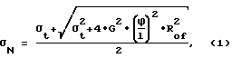
где l - нагружаемая длина образца,
![]()
Rof - радиус стеклянного волокна, E и v - соответственно модуль Юнга и коэффициент Пуассона материала образца. Для кварцевых стекол Е ~ 7200 кгс/мм2, v≈ 0.1682.As a measure of the mechanical strength of glass fibers, the value of the normal breaking stress σ N , which is calculated by the well-known formula [3], is used.
where l is the loaded length of the sample,
![]()
R of is the radius of the glass fiber, E and v are Young's modulus and Poisson's ratio of the sample material, respectively. For quartz glasses, E ~ 7200 kgf / mm 2 , v≈ 0.1682.
При проведении усталостных испытаний волоконных световодов важно обеспечить постоянство скорости нагружения [1]. Измерения значений медианной прочности при различных постоянных скоростях нагружения позволяют определить параметры процесса усталостного разрушения волоконного световода и, следовательно, построить научно обоснованный прогноз его долговечности. В случае, когда испытательное напряжение создается за счет совместного воздействия напряжений динамического кручения и динамического осевого растяжения, скорость нагружения оказывается постоянной только при постоянных (ненулевых) скоростях и осевого растяжения и динамического кручения. When carrying out fatigue tests of optical fibers, it is important to ensure a constant loading rate [1]. Measurements of the values of the median strength at various constant loading rates make it possible to determine the parameters of the process of fatigue failure of a fiber waveguide and, therefore, to construct a scientifically based forecast for its durability. In the case when the test stress is created due to the combined effects of dynamic torsion stresses and dynamic axial tension, the loading speed is constant only at constant (non-zero) speeds and axial tension and dynamic torsion.
Устройство-прототип имеет следующие недостатки:
оно является дорогим;
позволяет испытывать образцы только в лабораторной среде;
конструкция зажимов для образцов не обеспечивает высокой производительности труда оператора устройства и не позволяет испытывать современные волоконные световоды, покрытые защитными полимерными оболочками.The prototype device has the following disadvantages:
it is expensive;
allows you to test samples only in a laboratory environment;
the design of the clamps for samples does not provide high productivity for the operator of the device and does not allow testing of modern fiber optic fibers coated with protective polymer shells.
Дороговизна устройства вызвана наличием двух прецизионных механизмов нагружения: продольного растяжения образцов и их осевого закручивания и, соответственно, наличием двух измерителей: разрывного усилия и угла поворота стола с нижним зажимом. Устройство-прототип не позволяет исследовать свойства образцов в средах, отличных от лабораторной, поскольку из-за наличия поворотного стола не может быть использована стандартная климатическая камера разрывной машины. Процесс установки образцов для испытаний с помощью устройства-прототипа является длительным и неудобным. Требуется высокая точность установки образца: необходимо совместить его ось с осью вращения нижнего зажима с ошибкой, не превышающей значение диаметра образца. Вследствие того что верхний и нижний зажимы жестко закреплены в соответствующих узлах устройства-прототипа и оно не имеет никаких приспособлений для упрощения и ускорения процесса заправки, производительность труда оператора устройства оказывается низкой - много времени тратится на специальную подготовку образцов. The high cost of the device is caused by the presence of two precision loading mechanisms: the longitudinal tension of the samples and their axial twisting, and, accordingly, the presence of two meters: tensile strength and the angle of rotation of the table with the lower clamp. The prototype device does not allow to study the properties of samples in environments other than laboratory, because due to the presence of a rotary table, the standard climatic chamber of the tensile testing machine cannot be used. The process of installing test specimens using a prototype device is lengthy and inconvenient. High accuracy of sample installation is required: it is necessary to combine its axis with the axis of rotation of the lower clamp with an error not exceeding the value of the diameter of the sample. Due to the fact that the upper and lower clamps are rigidly fixed in the corresponding nodes of the prototype device and it does not have any devices to simplify and speed up the refueling process, the productivity of the device operator is low - a lot of time is spent on special sample preparation.
Устройство-прототип разрабатывалось и применялось для испытаний стеклянных волокон без защитного полимерного покрытия. В зажимах устройства-прототипа фиксировались стеклянные концы волокна, защищенные от воздействия жестких прижимных губок струбциночных зажимов картонными накладками. Современные волоконные световоды представляют собой многослойные конструкции: стеклянная световедущая часть покрыта снаружи несколькими защитными слоями полимеров. Обычно первичное полимерное покрытие, наносимое непосредственно на стекло, выполнено из мягкого полимера, а наружное - из жесткого. Попытка использовать при испытаниях таких волоконных световодов струбциночные зажимы с одним прижимным винтом (как у прототипа) выявила следующие трудности. Для эффективной фиксации концов образца необходимо сильно деформировать жесткое наружное покрытие так, чтобы мягкое первичное покрытие не могло играть роль "смазки" между наружным покрытием и стеклянной световедущей частью. Если прижим оказывается недостаточным, то крутящий момент не передается от зажима к стеклянной части волоконного световода и испытание образца провести не удается. Если же прижим оказывается слишком сильным, то образец может разрушиться на зажимах и измеренные значения прочности оказываются заниженными по сравнению с результатами испытаний этого же волоконного световода на разрывной машине с барабанными зажимами. Это проиллюстрировано на фиг.1. Здесь приведены результаты измерения прочности одномодового волоконного световода, имеющего двухслойное полимерное покрытие. На графике по оси абсцисс отложены значения разрывных усилий, эквивалентные измеренным значениям разрывных нормальных напряжений, а по оси ординат - вероятности P разрушения образцов. Эквивалентные разрывные усилия Fедн рассчитывались по формуле Fедн = σN•π•R
Целью предлагаемого изобретения является
удешевление устройства для измерения параметров процесса усталостного разрушения волоконных световодов (в том числе в условиях, отличных от лабораторных);
повышение производительности труда оператора устройства.The aim of the invention is
cheaper device for measuring the parameters of the process of fatigue fracture of optical fibers (including in conditions other than laboratory);
increasing the productivity of the device operator.
Поставленная цепь достигается благодаря тому, что предлагаемое устройство для испытаний образцов волоконных световодов на механическую усталость имеет
вертикальное основание;
узел с неподвижно закрепленным верхним зажимом (для фиксации верхнего конца испытываемого образца);
узел с неподвижно закрепленным нижним зажимом (для фиксации нижнего конца образца);
верхний и нижний зажимы струбциночного типа для фиксации концов образца;
согласно изобретению
устройство имеет привод для прецизионного управляемого вращения узла верхнего зажима относительно вертикальной оси;
устройство имеет индикатор разрушения образца волоконного световода, размещенный в верхней части вертикального основания устройства;
устройство имеет направляющие, которые обеспечивают свободное перемещение узла нижнего зажима в вертикальном направлении и препятствуют его вращению относительно вертикальной оси;
узлы верхнего и нижнего зажимов снабжены направляющими, оси которых перпендикулярны оси вращения волоконного световода, для свободного надвигания по ним соответствующих зажимов;
верхний и нижний зажимы имеют первые направляющие для совмещения с направляющими узлов верхнего и нижнего зажимов;
зажимы снабжены двумя или более прижимными винтами для фиксации образца;
верхний и нижний зажимы имеют вторые направляющие для совмещения оси образца волоконного световода с осью вращения верхнего зажима;
вес узла нижнего зажима Wcar выбрав таким, чтобы выполнялись условия
0.090 кгс ≤ Wcar ≤ 3.23 кгс; (3)
центр тяжести верхнего зажима смещен относительно оси вращения в сторону надвигания зажима.The circuit is achieved due to the fact that the proposed device for testing samples of optical fibers for mechanical fatigue has
vertical base;
a node with a fixed upper clamp (for fixing the upper end of the test sample);
a node with a fixed lower clamp (for fixing the lower end of the sample);
upper and lower clamp type clamps for fixing the ends of the sample;
according to the invention
the device has a drive for precision controlled rotation of the upper clamp assembly relative to the vertical axis;
the device has an indicator of destruction of the fiber sample, located in the upper part of the vertical base of the device;
the device has guides that provide free movement of the lower clamp assembly in the vertical direction and prevent its rotation relative to the vertical axis;
the nodes of the upper and lower clamps are provided with guides, the axes of which are perpendicular to the axis of rotation of the fiber, for the free movement of the respective clamps along them;
the upper and lower clamps have first guides for aligning with the guides of the nodes of the upper and lower clamps;
the clamps are provided with two or more clamping screws for fixing the sample;
the upper and lower clamps have second guides for aligning the axis of the sample of the fiber with the axis of rotation of the upper clamp;
the weight of the lower clamp assembly W car is chosen so that the conditions are met
0.090 kgf ≤ W car ≤ 3.23 kgf; (3)
the center of gravity of the upper clamp is offset relative to the axis of rotation in the direction of the clamp's sliding.
Изобретение поясняется чертежами. The invention is illustrated by drawings.
Фиг. 1. Сравнение распределения разрывной прочности волоконного световода, измеренной с помощью универсальной разрывной машины lnstron-1122, и крутильной прочности, измеренной с помощью устройства для испытаний волоконных световодов на механическую усталость путем одновременного воздействия на них напряжениями кручения и осевого растяжения. При крутильных испытаниях использовались струбциночные зажимы с одним прижимным винтом. FIG. 1. Comparison of the distribution of the tensile strength of a fiber waveguide, measured using a lnstron-1122 universal tensile machine, and the torsional strength, measured using a device for testing optical fibers for mechanical fatigue by simultaneously applying torsional and axial tensile stresses to them. During torsion tests, clamp clamps with one clamping screw were used.
Фиг. 2 Принципиальная схема устройства для испытаний образцов волоконных световодов на механическую усталость путем одновременного воздействия на них напряжениями динамического кручения и статического осевого растяжения. FIG. 2 Schematic diagram of a device for testing samples of optical fibers for mechanical fatigue by simultaneously acting on them with dynamic torsion stresses and static axial tension.
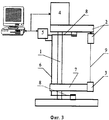
Фиг.3 Принципиальная схема реализованного устройства для испытаний образцов волоконных световодов на механическую усталость путем одновременного воздействия на них напряжениями динамического кручения и статического осевого растяжения. Figure 3 Schematic diagram of an implemented device for testing samples of optical fibers for mechanical fatigue by simultaneously exposing them to stresses of dynamic torsion and static axial tension.
Фиг. 4. Сравнение распределения разрывной прочности волоконного световода, измеренной с помощью универсальной разрывной машины lnstron-1122, и крутильной прочности, измеренной с помощью устройства для испытаний волоконных световодов на механическую усталость путем одновременного воздействия на них напряжениями динамического кручения и статического осевого растяжения. При крутильных испытаниях использовались струбциночные зажимы с двумя прижимными винтами. FIG. 4. Comparison of the distribution of the tensile strength of a fiber waveguide, measured using a lnstron-1122 universal tensile machine, and the torsional strength, measured using a device for testing fiber optic fibers for mechanical fatigue by simultaneously applying dynamic torsional stresses and static axial tensile stresses to them. During torsion tests, clamp clamps with two clamping screws were used.
Фиг.5 Принципиальная схема струбциночного зажима с двумя прижимными винтами для закрепления образцов волоконных световодов в устройстве для испытаний на механическую усталость путем одновременного воздействия на образцы напряжениями динамического кручения и статического осевого растяжения. Figure 5 Schematic diagram of a clamp clamp with two clamping screws for fixing samples of optical fibers in a device for testing mechanical fatigue by simultaneously affecting the samples with stresses of dynamic torsion and static axial tension.
Принципиальная схема предлагаемого устройства для испытаний образцов волоконных световодов на механическую усталость представлена на фиг.2. A schematic diagram of the proposed device for testing samples of optical fibers for mechanical fatigue is presented in figure 2.
Устройство содержит вертикальное основание 1, на котором закреплены все узлы устройства. Узел 2 с неподвижно закрепленным на нем верхним зажимом расположен в верхней части вертикального основания. Прецизионное управляемое вращение узла 2 относительно вертикальной оси осуществляется с помощью привода 4, состоящего из шагового электродвигателя (ШД) и редуктора. Использование шагового электродвигателя позволяет обойтись без измерителя угла поворота узла верхнего зажима, поскольку для высокоточного определения значения угла достаточно подсчитать количество шагов, выполненных ШД. В нижней части вертикального основания расположен узел 3 с неподвижно закрепленным нижним зажимом. Узел может свободно перемещаться в вертикальном направлении вдоль направляющих 6, которые в то же время препятствуют вращению узла относительно вертикальной оси. Благодаря этому осуществляется динамическое закручивание образца волоконного световода 9 с помощью привода узла верхнего зажима. В процессе выполнения испытаний узел нижнего зажима свободно висит на тестируемом волоконном световоде, осуществляя его статическое растяжение. При разрушении образца узел 3 падает вдоль направляющих 6 и изменяет состояние индикатора 5 разрушения образца волоконного световода. Электрическая часть индикатора 5, как и привод 4, расположены в верхней части вертикального основания 1. Индикатор разрушения образца волоконного световода является необходимым узлом предлагаемого устройства. В устройстве-прототипе признаком разрушения являлось резкое падение усилия растяжения, фиксируемое измерителем усилия растяжения при разрушении образца стеклянного волокна. Измеритель усилия растяжения является дорогим высокоточным элементом испытательного устройства, и его присутствие не является необходимым для обеспечения фиксации разрушения. Для этой цели достаточно индикатора, который имеет два состояния: "образец цел", "образец разрушен". The device contains a
Малый вес и компактность устройства в целом позволяют в отличие от устройства-прототипа использовать предлагаемое устройство для испытаний образцов в различных средах, например в воде. Вес предлагаемого устройства не превышает 4 кгс и скомпоновано оно так, что электрический привод для управляемого вращения узла верхнего зажима, а также электрическая часть индикатора разрушения образца волоконного световода расположены в верхней части вертикального основания устройства. Благодаря этому при погружении устройства в емкость с водой (аквариум) привод и электрическая часть индикатора оказываются выше уровня воды, что позволяет испытывать образцы в условиях 100% влажности. The low weight and compactness of the device as a whole make it possible, in contrast to the prototype device, to use the proposed device for testing samples in various environments, for example, in water. The weight of the proposed device does not exceed 4 kgf and it is arranged so that the electric drive for the controlled rotation of the upper clamp assembly, as well as the electrical part of the destruction indicator of the fiber sample, are located in the upper part of the vertical base of the device. Due to this, when the device is immersed in a container of water (an aquarium), the drive and the electrical part of the indicator are higher than the water level, which allows testing the samples in conditions of 100% humidity.
Устройство-прототип создано на основе универсальной разрывной машины, цена которой вместе с климатической камерой составляет ~ 20000 $. Предлагаемое устройство стоит ~ 3000 $. Такая разница в ценах вызвана следующими причинами. В устройстве-прототипе осевое растяжение образца создается за счет прецизионного управляемого вертикального перемещения узла верхнего зажима с помощью мощного привода универсальной разрывной машины. В предлагаемом устройстве статическое осевое растяжение образца создается за счет веса узла нижнего зажима, который в процессе проведения испытания свободно висит на образце волоконного световода. Вес этого узла известен, поэтому не нужен датчик усилия осевого растяжения образца, который необходим при использовании устройства-прототипа. The prototype device is based on a universal explosive machine, the price of which, together with the climate chamber, is ~ $ 20,000. The proposed device costs ~ $ 3000. This price difference is due to the following reasons. In the prototype device, the axial tension of the specimen is created due to the precision controlled vertical movement of the upper clamp assembly using a powerful drive of a universal tensile testing machine. In the proposed device, the static axial tension of the sample is created due to the weight of the lower clamp assembly, which during the test freely hangs on the sample of the optical fiber. The weight of this node is known, therefore, the axial tensile force sensor of the sample is not needed, which is necessary when using the prototype device.
Нормальные напряжения в образцах волоконных световодов при механических испытаниях методом кручения можно рассчитать, измеряя либо значения приложенного к образцу крутящего момента, либо значения деформации. Значения момента при разрушении волоконных световодов не превышают 0.1 кгс•мм. Для измерения столь малых значений момента силы не существует эталонов. Использование деформации для расчета разрушающего напряжения может привести к большим ошибкам, вызванным тем, что по-разному деформируется часть образца, находящаяся между зажимами, и концы образца на зажимах. Деформацию волоконного световода можно описать, вводя эффективную длину [4] образца, которая отличается от расстояния между зажимами (то есть нагружаемой длины образца) тем больше, чем больше деформируемая длина волоконного световода на зажимах. Трудность состоит в том, что длина, на которой деформация образца на зажимах уменьшается до нуля, зависит от ее максимального значения. При разработке конструкции зажимов для испытаний волоконных световодов методом динамического кручения особое внимание было уделено тому, чтобы минимизировать разницу между нагружаемой и эффективной длиной образцов. Успешное решение этой задачи позволило использовать значения деформации образцов для расчета разрушающих нормальных напряжений. The normal stresses in the samples of optical fibers during mechanical tests by the torsion method can be calculated by measuring either the values of the torque applied to the sample or the values of deformation. The values of the moment during the destruction of fiber fibers do not exceed 0.1 kgf • mm. To measure such small values of the moment of force, there are no standards. The use of deformation for calculating the breaking stress can lead to large errors caused by the fact that the part of the sample located between the clamps and the ends of the sample on the clamps are deformed differently. The deformation of the fiber can be described by introducing the effective length [4] of the sample, which differs from the distance between the clamps (that is, the loaded length of the sample) the greater, the greater the deformable length of the fiber at the clips. The difficulty is that the length at which the deformation of the sample at the clamps decreases to zero depends on its maximum value. In developing the design of clamps for testing fiber optic fibers by dynamic torsion, special attention was paid to minimize the difference between the loaded and effective lengths of the samples. The successful solution of this problem made it possible to use the values of sample deformation for calculating destructive normal stresses.
В устройстве-прототипе применены зажимы струбциночного типа с одним прижимным винтом. При использовании таких зажимов велика вероятность повреждения поверхности волоконного световода на зажиме. Вследствие этого распределение прочности, измеренное на крутильной машине с такими струбциночными зажимами, оказывается сдвинутым в область малых прочностей по сравнению с распределением прочности, полученным при испытаниях образцов этого же волоконного световода на разрывной машине с барабанными зажимами (см. фиг.1). На фиг.4 представлено сравнение распределений прочности одного и того же волоконного световода, измеренных на крутильной машине, снабженной струбциночными зажимами с двумя прижимными винтами (как у предлагаемого устройства), и с помощью разрывной машины, снабженной барабанными зажимами. Видно, что при использовании струбциночных зажимов с двумя прижимными винтами распределение крутильной прочности совпадает с распределением разрывной прочности. Это связано с тем, что при использовании таких зажимов не происходит повреждения и разрушения образцов на зажимах. The prototype device uses clamp type clamps with one clamping screw. When using such clamps, there is a high probability of damage to the surface of the fiber waveguide on the clamp. As a result, the distribution of strength, measured on a torsion machine with such clamping clamps, is shifted to the region of low strengths compared with the distribution of strength obtained by testing samples of the same fiber waveguide on a tensile testing machine with drum clamps (see figure 1). Figure 4 presents a comparison of the distribution of strength of the same fiber, measured on a twisting machine equipped with clamping clamps with two clamping screws (as with the proposed device), and using a tensile testing machine equipped with drum clamps. It is seen that when using clamps with two clamping screws, the distribution of torsional strength coincides with the distribution of tensile strength. This is due to the fact that when using such clamps, damage and destruction of samples on the clamps does not occur.
В то же время такие зажимы тоже относятся к классу струбциночных, поскольку, согласно БСЭ (издание второе, т. 41, стр. 147), струбцинка представляет собой прямоугольную раму, через один из длинных брусьев которой пропущен один или несколько прижимных винтов. At the same time, such clamps also belong to the class of clamping clamps, since, according to TSB (second edition, vol. 41, p. 147), the clamp is a rectangular frame through which one or several clamping screws are passed through one of the long bars.
Для удобства заправки, повышения точности установки образцов и увеличения производительности труда оператора испытательного устройства узлы верхнего и нижнего зажимов имеют направляющие, совместимые с первыми направляющими на верхнем и нижнем зажимах. Оси тех и других направляющих перпендикулярны оси вращения образца. Благодаря этому зажимы легко снимаются и устанавливаются в узлах. Это позволяет заправлять образцы в зажимы вне устройства и затем свободно надвигать зажимы по направляющим, находящимся на узлах верхнего и нижнего зажимов. For the convenience of refueling, increasing the accuracy of the installation of samples and increasing the productivity of the operator of the test device, the nodes of the upper and lower clamps have guides compatible with the first guides on the upper and lower clamps. The axes of those and other guides are perpendicular to the axis of rotation of the sample. Due to this, the clamps are easily removed and installed in nodes. This allows samples to be inserted into the clamps outside the device and then to freely slide the clamps along the guides located on the nodes of the upper and lower clamps.
Для обеспечения высокой точности совмещения оси образца волоконного световода с осью вращения верхнего зажима верхний и нижний зажимы снабжены вторыми направляющими, которые позволяют совместить ось вращения зажима с осью волоконного световода с ошибкой, не превышающей 0.1 мм, то есть менее радиуса образца. To ensure high accuracy of alignment of the axis of the sample of the fiber with the axis of rotation of the upper clamp, the upper and lower clamps are equipped with second guides that allow you to combine the axis of rotation of the clamp with the axis of the fiber with an error not exceeding 0.1 mm, i.e. less than the radius of the sample.
Предлагаемое устройство для испытаний образцов волоконных световодов на механическую усталость функционирует следующим образом. Оператор снимает зажимы с узлов и, используя вторые направляющие, вставляет в зажимы концы заранее отрезанного образца волоконного световода. Затем концы образца фиксируются за счет затягивания прижимных винтов струбцинок и зажимы с закрепленным в них образцом надвигаются по направляющим в узлах 2 и 3. Узел 3 удерживается от перемещения в вертикальном направлении за счет упругости образца 9. Индикатор разрушения образца находится в состоянии "образец цел". The proposed device for testing samples of optical fibers for mechanical fatigue operates as follows. The operator removes the clamps from the nodes and, using the second guides, inserts the ends of the pre-cut sample of the optical fiber into the clamps. Then the ends of the sample are fixed by tightening the clamping screws of the clamps and the clamps with the sample fixed in them are pushed along the guides in
После этого включается ШД привода 4 и образец подвергается закручиванию относительно вертикальной оси. Для того чтобы при вращении верхний зажим не слетал с направляющей узла 2 его центр тяжести смещен относительно оси вращения в сторону надвигания зажима. Таким образом, при вращении зажим прижимается к опорной поверхности центробежной силой. Волоконный световод испытывает одновременное воздействие статического осевого растяжения за счет веса узла 3 с нижним зажимом и напряжения динамического кручения, создаваемого с помощью прецизионного привода 4. После достижения нормальным напряжением разрушающего значения и разрушения образца узел 3 падает вдоль направляющих 6, изменяя состояние индикатора 5 разрушения образца волоконного световода на "образец разрушен". При этом фиксируется значение угла поворота ШД, выполненного с момента начала испытания. Значение разрушающего напряжения рассчитывается с помощью соотношения (6) (см. ниже) или (1), в которых угол φ равен значению угла поворота узла верхнего зажима относительно оси образца, выполненного приводом 4, и значение W равно весу узла 3 с нижним зажимом. При проведении испытаний в аквариуме вес узла 3 уменьшается на архимедову силу. After this, the
Вес узла нижнего зажима выбирается таким (3), чтобы обеспечить механическую устойчивость и постоянство скорости нагружения тестируемых образцов. Благодаря этому устройство используется для измерения параметров процесса механической усталости волоконных световодов. Кручение волоконного световода при выполнении испытаний может привести к потере им механической устойчивости, при этом ось образца образует сложную пространственную кривую, и напряжение, действующее на него, оказывается очень сложным. В этом случае интерпретация результатов испытаний затруднена. Для того чтобы потери устойчивости не происходило, достаточно приложить к образцу дополнительное растяжение σt, превышающее некоторое критическое значение σzer:
σzer≤σt.
Испытания показывают, что для волоконных световодов σzer≈ 10-3 • Е, так что при испытании с помощью предлагаемого устройства потери устойчивости образцов удается избежать, если вес узла 3 с нижним зажимом удовлетворяет условию
10-3•E•π•R
В случае, когда испытательное напряжение в образце создается за счет совместного воздействия напряжениями динамического кручения и статического осевого растяжения, невозможно обеспечить постоянство скорости нагружения во всем диапазоне значений нормального напряжения. При выполнении испытаний с целью определения параметров механической усталости волоконных световодов важно обеспечить постоянство скорости увеличения нормального напряжения ![]()
Wcar≤3,6•10-2•E•π•R
то значение нормального напряжения (1) в указанном диапазоне значений нормальных напряжений с точностью до единиц процентов определяется выражением
![]()
так что скорость нагружения при закручивании образца составляет
![]()
Таким образом, скорость нагружения ![]()
![]()
10-3•E•π•R
Для стандартных кварцевых волоконных световодов диаметром 125 мкм условия (7) принимают вид
0.090 кгс ≤ Wcar ≤ 3.23 кгс. (8)
Таким образом, предлагаемое устройство характеризуется новой совокупностью признаков, которая позволяет достичь нового технического свойства, не являющегося суммарным эффектом: выполнить испытания образцов волоконных световодов на механическую усталость путем одновременного воздействия на них напряжениями динамического кручения и статического осевого растяжения. Благодаря указанным выше существенным признакам устройство позволяет проводить испытания образцов волоконных световодов в различных средах, в частности в условиях 100% влажности, обеспечивает высокую точность получаемых результатов (не уступающую точности результатов при испытании образцов на разрывной машине) и постоянство скорости нагружения (в указанном диапазоне напряжений), необходимое для получения характеристик механической усталости.The weight of the lower clamp assembly is chosen such (3) to ensure mechanical stability and constant loading speed of the tested samples. Due to this, the device is used to measure the parameters of the process of mechanical fatigue of optical fibers. Torsion of the fiber during testing can lead to loss of mechanical stability, while the axis of the sample forms a complex spatial curve, and the voltage acting on it is very complex. In this case, the interpretation of the test results is difficult. In order to prevent stability loss, it is enough to apply an additional tensile σ t to the sample that exceeds some critical value of σ zer :
σ zer ≤σ t .
Tests show that for fiber fibers σ zer ≈ 10 -3 • E, so that when tested with the proposed device, the loss of stability of the samples can be avoided if the weight of
10 -3 • E • π •
In the case when the test stress in the sample is created due to the combined action of dynamic torsion stresses and static axial tension, it is impossible to ensure a constant loading rate over the entire range of normal stress values. When performing tests to determine the parameters of mechanical fatigue of optical fibers, it is important to ensure a constant rate of increase in normal voltage ![]()
W car ≤3.6 • 10 -2 • E • π •
then the value of the normal voltage (1) in the specified range of values of normal stresses with an accuracy of units of percent is determined by the expression
![]()
so that the loading speed when twisting the sample is
![]()
Thus, the loading rate ![]()
![]()
10 -3 • E • π •
For standard quartz fiber optical fibers with a diameter of 125 μm, conditions (7) take the form
0.090 kgf ≤ W car ≤ 3.23 kgf. (8)
Thus, the proposed device is characterized by a new set of features, which allows to achieve a new technical property, which is not the total effect: to test samples of fiber optical fibers for mechanical fatigue by simultaneously influencing them with dynamic torsional stresses and static axial tension. Due to the above mentioned essential features, the device allows testing fiber fiber samples in various environments, in particular in conditions of 100% humidity, provides high accuracy of the results obtained (not inferior to the accuracy of the results when testing samples on a tensile testing machine) and constant loading speed (in the specified voltage range ) necessary to obtain the characteristics of mechanical fatigue.
По простоте и дешевизне предлагаемое устройство превосходит все известные устройства для выполнения усталостных испытаний волоконных световодов [1] , а по точности и применимости для выполнения прогноза долговечности волоконных световодов в различных эксплуатационных условиях не уступает разрывным машинам. In terms of simplicity and low cost, the proposed device is superior to all known devices for performing fatigue tests of optical fibers [1], and in terms of accuracy and applicability for predicting the durability of optical fibers under various operating conditions, it is not inferior to tensile testing machines.
ПРИМЕР РЕАЛИЗАЦИИ
Предлагаемое устройство для испытаний образцов волоконных световодов на механическую усталость реализовано (см. фиг.3) и испытано. Стоимость конструкторских работ, работы по реализации устройства в металле и разработка программного обеспечения для управления устройством с помощью персонального компьютера составила около 3000 $.EXAMPLE OF IMPLEMENTATION
The proposed device for testing samples of optical fibers for mechanical fatigue is implemented (see figure 3) and tested. The cost of design work, work on the implementation of the device in metal and the development of software for controlling the device using a personal computer amounted to about $ 3000.
На верхней части вертикального основания 1 устройства расположен узел 2 с неподвижно закрепленным верхним зажимом. Узлы 2 и 3 верхнего и нижнего зажимов имеют направляющие, оси которых перпендикулярны оси вращения волокна, для совмещения с первыми направляющими соответствующих зажимов. Были реализованы направляющие типа "ласточкин хвост" и "гильза-направляющий стержень". Узел 2 приводится во вращение относительно вертикальной оси с помощью привода 4 на основе шагового двигателя ДШИ-200-3. Узел 3 с неподвижно закрепленным нижним зажимом представляет собой каретку 7, которая свободно перемещается в вертикальном направлении вдоль двух направляющих. В качестве одной направляющей используется вертикальное основание 1 устройства. Вторая направляющая 6 выполняет также функцию тяги индикатора 5 разрушения образца волоконного световода. On the upper part of the
Для удобства работы оператора испытательное устройство имеет фиксатор, который ограничивает вертикальные перемещения узла 3. Фиксатор используется при установке в устройство зажимов с закрепленным в них образцом. Перед началом испытаний оператор с помощью фиксатора устанавливает узел 3 в таком положении, чтобы расстояние между верхним и нижним зажимами оказалось несколько меньше длины тестируемых образцов. При установке образца сначала надвигается по направляющим узла 2 верхний зажим. Затем по направляющим зафиксированного узла 3 надвигается нижний зажим. При этом образец не ограничивает необходимые перемещения зажимов и не мешает выполнять эти операции. Перед включением нагружающего двигателя оператор освобождает фиксатор и узел нижнего зажима 3 повисает на образце, создавая в последнем статическое растягивющее напряжение σt.
Электрическая часть индикатора разрушения образца волоконного световода расположена на верхней части вертикального основания устройства и представляет собой пару: светодиод - фотодиод. Световой поток от светодиода на фотодиод перекрывается с помощью непрозрачного лепестка, укрепленного на верхней части направляющей 6, которая может перемещаться в вертикальном направлении. Нижний и верхний концы направляющей прикреплены к пластинчатым пружинам 8, расположенным на нижней и верхней частях установки. Под действием пружин направляющая занимает положение, при котором лепесток перекрывает световой поток от светодиода к фотодиоду. После разрушения образца 9 каретка с нижним зажимом падает вниз, изгибает пружины и сдвигает направляющую 6 так, что на фотодиод начинает поступать световой поток от светодиода. Вращение узла с нижним зажимом относительно вертикальной оси блокируется благодаря наличию двух указанных выше направляющих. В то же время направляющие не мешают вертикальному перемещению этого узла.For the convenience of the operator, the test device has a latch that restricts the vertical movement of the
The electrical part of the destruction indicator of the fiber sample is located on the upper part of the vertical base of the device and is a pair: LED - photodiode. The luminous flux from the LED to the photodiode is blocked by an opaque petal mounted on the upper part of the guide 6, which can be moved in the vertical direction. The lower and upper ends of the guide are attached to
Устройство имеет струбцинонные зажимы для закрепления концов испытываемых образцов. На фиг.5 представлена принципиальная схема верхнего зажима и часть 10 узла верхнего зажима с направляющей 12 для свободного надвигания зажима. Конструктивно верхний и нижний зажимы одинаковы. Размеры зажимов подбирались таким образом, чтобы их центр тяжести был сдвинут относительно оси вращения верхнего зажима в направлении надвигания на направляющие узла верхнего зажима. Каждый зажим имеет корпус 11, первую направляющую 13 (совместимую с направляющей 12 узла верхнего или нижнего зажима) для быстрой установки зажима на испытательное устройство, прижимные винты 14. Вторые направляющие 15 и 16, фиксирующие конец образца 9 в двух точках: при входе в зажимающую струбцину и при выходе из нее, изготовлены из материала, не повреждающего образец (например, из капролона). Благодаря этому ось испытываемого волоконного световода совмещается с осью вращения верхнего зажима с ошибкой, не превышающей 0.1 мм, то есть менее радиуса образца (на фиг.5 изображены два прижимных винта; при необходимости их количество может быть увеличено). The device has clamp clamps for securing the ends of the test samples. Figure 5 presents a schematic diagram of the upper clamp and
Оператор управляет устройством и получает результаты испытания с помощью персонального компьютера. The operator controls the device and receives the test results using a personal computer.
Реализованные варианты конструкции узлов устройства не исчерпывают всех возможных конструктивных вариантов построения устройства. Например, вертикальное основание устройства может быть выполнено в виде трубы с вырезами для зажимов, индикатор разрушения образца волоконного световода может быть реализован с помощью герконов, управление устройством не обязательно должно осуществляться с помощью персонального компьютера и т.д. The implemented design options for the nodes of the device do not exhaust all possible structural options for constructing the device. For example, the vertical base of the device can be made in the form of a pipe with cutouts for clamps, an indicator of the destruction of a fiber sample can be implemented using reed switches, the device does not have to be controlled using a personal computer, etc.
Для оценки точности результатов испытаний было выполнено сравнение результатов измерения распределения прочности волоконных световодов на универсальной разрывной машине Instron-1122 и на устройстве для испытаний образцов волоконных световодов на механическую усталость методом одновременного воздействия на них напряжениями динамического кручения и статического осевого растяжения. Два рандомизированных ансамбля образцов были нарезаны из одного и того же одномодового волоконного световода с двухслойным полимерным покрытием и испытаны на двух устройствах. Диаметр стеклянной части волоконного световода составлял 0.125 мм, наружный диаметр в покрытии был равен 0.255 мм. В качестве первичного покрытия использован полимер DeSolite 950-106, толщина покрытия составляла 0.04 мм. Материал вторичного покрытия - полимер DeSolite 950-108, толщина покрытия 0.025 мм. При испытаниях использовался набор дополнительных грузов, которые навешивались на каретку 7 с нижним зажимом. Набор дополнительных грузов позволил перекрыть весь диапазон значений статического растяжения (8). Для того чтобы обеспечить возможность проведения испытаний в воде и других агрессивных средах, а также реализовать дополнительное усилие растяжения ~ 0.1 кгс, из титана были изготовлены специальные зажимы струбциночного типа с двумя прижимными винтами каждый. To assess the accuracy of the test results, a comparison was made of the results of measuring the distribution of strength of optical fibers on an Instron-1122 universal tensile testing machine and on a device for testing samples of optical fibers for mechanical fatigue by the simultaneous action of dynamic torsional stresses and static axial tension on them. Two randomized ensembles of samples were cut from the same single-mode fiber with a two-layer polymer coating and tested on two devices. The diameter of the glass part of the fiber was 0.125 mm, and the outer diameter in the coating was 0.255 mm. The primary coating used was DeSolite 950-106 polymer, the coating thickness was 0.04 mm. The material of the secondary coating is DeSolite 950-108 polymer, the coating thickness is 0.025 mm. During the tests, a set of additional weights was used, which were hung on the
Результаты испытаний при всех дополнительных грузах сведены вместе и представлены на фиг. 4 (экспериментальные точки, отмеченные знаком "о"). Здесь же для сравнения приведены результаты испытания второго ансамбля образцов на разрывной машине с барабанными зажимами (экспериментальные точки, отмеченные знаком "х"). На графике по оси абсцисс отложены значения разрывных усилий, эквивалентные измеренным значениям разрывных нормальных напряжений, а по оси ординат - вероятности Р разрушения образцов. The test results for all additional weights are brought together and presented in FIG. 4 (experimental points marked with an o). Here, for comparison, the test results of the second ensemble of samples on a tensile testing machine with drum clamps are shown (experimental points marked with an x). On the graph, the abscissa axis shows the values of tensile forces equivalent to the measured values of normal tensile stresses, and the ordinates show the probabilities P of fracture of the samples.
Из графиков на фиг.4 видно, что измеренные распределения прочности совпадают. Это означает, что точности измерения усталостных характеристик волоконных световодов на универсальной разрывной машине и с помощью предлагаемого устройства одинаковы во всем указанном выше диапазоне значений усилия статического растяжения образцов. С помощью предлагаемого устройства были измерены также распределения прочности волоконных световодов в условиях 100% влажности при различных скоростях нагружения. Эти измерения позволили получить значения параметров механической усталости волоконных световодов при различных внешних условиях и выполнить прогноз их долговечности. Устройство-прототип не позволяет получить такие результаты. From the graphs in figure 4 it is seen that the measured distribution of strength coincide. This means that the accuracy of the measurement of the fatigue characteristics of the optical fibers on a universal tensile machine and using the proposed device are the same in the entire range of values of the static tension of the samples indicated above. Using the proposed device were also measured the distribution of the strength of the optical fibers in conditions of 100% humidity at various loading speeds. These measurements made it possible to obtain the values of the mechanical fatigue parameters of optical fibers under various environmental conditions and to make a prediction of their durability. The prototype device does not allow to obtain such results.
Литература
1. International Electrotechnical Commission. Draft International Standard 86A/302/DIS, Project number 86A/793-1-3/Ed.1.Literature
1. International Electrotechnical Commission. Draft International Standard 86A / 302 / DIS, Project number 86A / 793-1-3 / Ed. 1.
2. William J. Kroenke. "Torsional testing techniques applied to fine diameter glass fibres". The Glass Industry, v. 47, 5, p.p. 262-266, 282-284, 1966. 2. William J. Kroenke. "Torsional testing techniques applied to fine diameter glass fibers." The Glass Industry, v. 47, 5, p.p. 262-266, 282-284, 1966.
3. С.П. Тимошенко, Дж. Гудьер. Теория упругости, М.: Наука, 1975. 3.S.P. Tymoshenko, J. Goodyear. Theory of elasticity, Moscow: Nauka, 1975.
4. И. В. Александров, М. Е. Жаботинский, С.Я. Фельд, О.Е. Шушпанов. "Оптимизация барабанных зажимов при статических и динамических испытаниях волоконных световодов". - Журнал технической физики, т. 61, 11, стр. 140-150 (1991). 4. I.V. Aleksandrov, M.E. Zhabotinsky, S.Ya. Feld, O.E. Shushpanov. "Optimization of drum clamps in static and dynamic tests of optical fibers." - Journal of Technical Physics, vol. 61, 11, pp. 140-150 (1991).
Claims (1)
Priority Applications (1)
| Application Number | Priority Date | Filing Date | Title |
|---|---|---|---|
| RU2001103040A RU2200309C2 (en) | 2001-02-06 | 2001-02-06 | Gear testing fiber-optical light guides for mechanical fatigue |
Applications Claiming Priority (1)
| Application Number | Priority Date | Filing Date | Title |
|---|---|---|---|
| RU2001103040A RU2200309C2 (en) | 2001-02-06 | 2001-02-06 | Gear testing fiber-optical light guides for mechanical fatigue |
Publications (2)
| Publication Number | Publication Date |
|---|---|
| RU2200309C2 true RU2200309C2 (en) | 2003-03-10 |
| RU2001103040A RU2001103040A (en) | 2004-03-20 |
Family
ID=20245531
Family Applications (1)
| Application Number | Title | Priority Date | Filing Date |
|---|---|---|---|
| RU2001103040A RU2200309C2 (en) | 2001-02-06 | 2001-02-06 | Gear testing fiber-optical light guides for mechanical fatigue |
Country Status (1)
| Country | Link |
|---|---|
| RU (1) | RU2200309C2 (en) |
Cited By (4)
| Publication number | Priority date | Publication date | Assignee | Title |
|---|---|---|---|---|
| RU2238536C1 (en) * | 2003-05-30 | 2004-10-20 | Институт радиотехники и электроники РАН | Clamp for testing fiber-optic light conduit |
| RU2319130C1 (en) * | 2006-06-27 | 2008-03-10 | Институт радиотехники и электроники Российской Академии Наук | Device for fatigue test of fiber light guides |
| RU2399035C1 (en) * | 2009-06-29 | 2010-09-10 | Учреждение Российской академии наук Институт радиотехники и электроники им. В.А. Котельникова РАН | Method of measuring parametres characterising strength and "healing" properties of nanosize molecular structures formed on surface of fibre-optic guides during manufacture |
| RU2612949C2 (en) * | 2015-08-04 | 2017-03-14 | федеральное государственное бюджетное образовательное учреждение высшего образования "Костромской государственный университет" (КГУ) | Portable breaking machine for testing threads at monoaxial stretching |
Citations (3)
| Publication number | Priority date | Publication date | Assignee | Title |
|---|---|---|---|---|
| SU183464A1 (en) * | ВСЕСО ОЗаЛ | DOSING DEVICE TO THE DYNOMOMETER FOR DETERMINATION OF THE STRENGTH OF A FIBER BEAM | ||
| SU1654723A1 (en) * | 1989-01-16 | 1991-06-07 | Предприятие П/Я А-3697 | Method of determining rigidity upon twist testing |
| US5460052A (en) * | 1994-07-28 | 1995-10-24 | University Of Massachusetts Lowell | Apparatus and method for measuring composite interface properties |
-
2001
- 2001-02-06 RU RU2001103040A patent/RU2200309C2/en not_active IP Right Cessation
Patent Citations (3)
| Publication number | Priority date | Publication date | Assignee | Title |
|---|---|---|---|---|
| SU183464A1 (en) * | ВСЕСО ОЗаЛ | DOSING DEVICE TO THE DYNOMOMETER FOR DETERMINATION OF THE STRENGTH OF A FIBER BEAM | ||
| SU1654723A1 (en) * | 1989-01-16 | 1991-06-07 | Предприятие П/Я А-3697 | Method of determining rigidity upon twist testing |
| US5460052A (en) * | 1994-07-28 | 1995-10-24 | University Of Massachusetts Lowell | Apparatus and method for measuring composite interface properties |
Cited By (5)
| Publication number | Priority date | Publication date | Assignee | Title |
|---|---|---|---|---|
| RU2238536C1 (en) * | 2003-05-30 | 2004-10-20 | Институт радиотехники и электроники РАН | Clamp for testing fiber-optic light conduit |
| RU2319130C1 (en) * | 2006-06-27 | 2008-03-10 | Институт радиотехники и электроники Российской Академии Наук | Device for fatigue test of fiber light guides |
| RU2319130C9 (en) * | 2006-06-27 | 2008-06-27 | Институт радиотехники и электроники Российской Академии Наук | Device for fatigue test of fiber light guides |
| RU2399035C1 (en) * | 2009-06-29 | 2010-09-10 | Учреждение Российской академии наук Институт радиотехники и электроники им. В.А. Котельникова РАН | Method of measuring parametres characterising strength and "healing" properties of nanosize molecular structures formed on surface of fibre-optic guides during manufacture |
| RU2612949C2 (en) * | 2015-08-04 | 2017-03-14 | федеральное государственное бюджетное образовательное учреждение высшего образования "Костромской государственный университет" (КГУ) | Portable breaking machine for testing threads at monoaxial stretching |
Also Published As
| Publication number | Publication date |
|---|---|
| RU2001103040A (en) | 2004-03-20 |
Similar Documents
| Publication | Publication Date | Title |
|---|---|---|
| RU2200309C2 (en) | Gear testing fiber-optical light guides for mechanical fatigue | |
| DE3914147A1 (en) | SENSOR FOR DETECTING REAGENT CONCENTRATIONS | |
| Lines et al. | Explanation of anomalous loss in high delta singlemode fibres | |
| Lu et al. | Recent developments in hermetically coated optical fiber | |
| Glaesemann | Advancements in mechanical strength and reliability of optical fibers | |
| RU2194966C2 (en) | Method predicting time of no-failure operation of light guides | |
| Evano et al. | Lifetime modeling of silica optical fiber in static fatigue test | |
| RU2238536C1 (en) | Clamp for testing fiber-optic light conduit | |
| Cuellar et al. | Static fatigue lifetime of optical fibers in bending | |
| Setchell | Damage studies in high-power fiber transmission systems | |
| Kennedy et al. | Stress-free aging of optical fiber in water and humid environments: Part 2 | |
| SU1755110A1 (en) | Device for fatigue testing of specimens | |
| Glaesemann et al. | Quantifying the puncture resistance of optical fiber coatings | |
| Bogatyrev et al. | Investigation of the mechanical strength of fiber-optic waveguides used in optical communications systems | |
| CN116773577B (en) | Optical fiber foreign matter detection device and preparation method thereof | |
| SE9301883L (en) | Method and apparatus for determining the life of a fiber | |
| RU2319130C9 (en) | Device for fatigue test of fiber light guides | |
| Svensson | Evaluation of B-values of telecom fibers, objectives and methods | |
| Smith et al. | Mechanical behavior of optical fibers removed from a field-aged cable | |
| Betz et al. | Fiberoptic smart sensing of component deformations in adaptive wings | |
| Suhir | Fiber Optics Structural Mechanics and Nano-Technology Based New Generation of Fiber Coatings: Review and Extension | |
| Lofts et al. | Development of sensing coils for an ultraminiaturized tactical fiber gyroscope | |
| Ellis et al. | Pcs Cable Connector Termination, Radiation Exposure, And Testing | |
| Lin et al. | Modeling of extrinsic defects in silica fibers using Vickers identification | |
| Estep et al. | Effect of carbon overcoating on the mechanical behavior of large flaws |
Legal Events
| Date | Code | Title | Description |
|---|---|---|---|
| MZ4A | Patent is void |
Effective date: 20081222 |