RU2198744C2 - Sieve - Google Patents
Sieve Download PDFInfo
- Publication number
- RU2198744C2 RU2198744C2 RU2001103611/03A RU2001103611A RU2198744C2 RU 2198744 C2 RU2198744 C2 RU 2198744C2 RU 2001103611/03 A RU2001103611/03 A RU 2001103611/03A RU 2001103611 A RU2001103611 A RU 2001103611A RU 2198744 C2 RU2198744 C2 RU 2198744C2
- Authority
- RU
- Russia
- Prior art keywords
- sieve
- groove
- annular
- cloth
- screening cloth
- Prior art date
Links
Images
Landscapes
- Combined Means For Separation Of Solids (AREA)
Abstract
Description
Изобретение относится к области разделения или сортировки сыпучих материалов, в частности, к устройствам для сортировки продуктов помола. The invention relates to the field of separation or sorting of bulk materials, in particular, to devices for sorting grinding products.
Известно сито (см. , например, авт.св. СССР 2015750, кл. B 07 B 1/00, 1991 г. ), содержащее просеивающее полотно, которое выполнено с участками, имеющими большее и меньшее сечения ячеек. A sieve is known (see, for example, Aut. St. USSR 2015 750, class B 07 B 1/00, 1991) containing a screening cloth that is made with sections having a larger and smaller section of cells.
Ни в одной из известных конструкций сит не решается задача обеспечения постоянного натяжения просеивающего полотна. None of the known sieve designs solve the problem of ensuring constant tension of the screening cloth.
За прототип выбрано сито цилиндрической формы (см., например, заявку Франции 2187426, кл. B 07 B 1/48, опубл. 18.01.1974), содержащее просеивающее полотно, обойму, в которой выполнена кольцевая проточка, размещенный в проточке обоймы поверх просеивающего полотна кольцевой вкладыш, ширина которого соответствует ширине проточки. For the prototype, a cylindrical sieve was selected (see, for example, French application 2187426, class B 07 B 1/48, publ. 01/18/1974) containing a screening cloth, a cage in which an annular groove is made, placed in the casing groove over the screening web annular liner, the width of which corresponds to the width of the groove.
В устройстве-прототипе обеспечивается натяжение просеивающего полотна, но оно сложно и нетехнологично. The prototype device provides the tension of the screening cloth, but it is difficult and low-tech.
Предложенное изобретение направлено на решение указанной задачи простыми средствами. The proposed invention is aimed at solving this problem by simple means.
Для этого в предложенном сите цилиндрической формы, содержащем просеивающее полотно, обойму, в которой выполнена кольцевая проточка, размещенный в проточке обоймы поверх просеивающего полотна кольцевой вкладыш, ширина которого соответствует ширине проточки, просеивающее полотно и торец кольцевого вкладыша установлены с прижатием к донной части кольцевой проточки, при этом для дополнительного крепления просеивающего полотна внутренняя поверхность кольцевой проточки, ее дно, покрыто клеящим составом. To do this, in the proposed sieve of cylindrical shape containing a screening cloth, a cage in which an annular groove is made, an annular insert is placed in the casing groove over the screening cloth, the width of which corresponds to the groove width, the sifting cloth and the end of the annular insert are installed with the ring groove pressed to the bottom at the same time, for additional fastening of the screening cloth, the inner surface of the annular groove, its bottom, is covered with an adhesive composition.
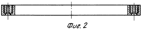
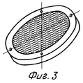
Изобретение поясняется чертежом, где на фиг.1 представлена конструкция сита; на фиг.2 показано сито в собранном виде; на фиг.3 - общий вид сита. The invention is illustrated in the drawing, where figure 1 shows the design of the sieve; figure 2 shows the sieve in assembled form; figure 3 is a General view of the sieve.
Сито цилиндрической формы (см. фиг.1) содержит кольцевой вкладыш 1, просеивающее полотно 2, натянутое на обойму 3, в которой выполнена кольцевая проточка 4, а также винт 5 и отверстия 6, 7 под винт в кольцевом вкладыше 1 и в обойме 3 соответственно. The sieve of cylindrical shape (see Fig. 1) contains an annular liner 1, a
При изготовлении сита на обойму 3 со стороны кольцевой проточки 4 натягивается просеивающее полотно 2 с необходимым усилием P (см. фиг.1). На натянутое просеивающее полотно 2 над кольцевой проточкой 4 в обойме 3 устанавливается кольцевой вкладыш 1. Приложенным усилием P1 кольцевой вкладыш 1 вместе с просеивающим полотном вдавливается в проточку 4, внутренняя поверхность которой покрыта клеящим составом, например, клеем. Для повышения надежности закрепления просеивающего полотна 2 на обойме 3 предусмотрено дополнительное крепление с помощью винта 5, для чего в обойме и в теле кольцевого вкладыша 1 выполнены отверстия 7 и 6. Количество таких отверстий зависит от диаметра сита.In the manufacture of the sieve on the cage 3 from the side of the annular groove 4 stretches the
Такое выполнение сита обеспечивает надежность крепления просеивающего полотна и увеличивает срок его эксплуатации без снижения силы его натяжения на обойме простыми средствами, что повышает технологичность изготовления и, в конечном итоге, качество выходных продуктов помола. This embodiment of the sieve ensures the reliability of the fastening of the screening cloth and increases its life without reducing the force of tension on the cage by simple means, which increases the manufacturability and, ultimately, the quality of the output grinding products.
Claims (1)
Priority Applications (1)
| Application Number | Priority Date | Filing Date | Title |
|---|---|---|---|
| RU2001103611/03A RU2198744C2 (en) | 2001-02-09 | 2001-02-09 | Sieve |
Applications Claiming Priority (1)
| Application Number | Priority Date | Filing Date | Title |
|---|---|---|---|
| RU2001103611/03A RU2198744C2 (en) | 2001-02-09 | 2001-02-09 | Sieve |
Publications (2)
| Publication Number | Publication Date |
|---|---|
| RU2001103611A RU2001103611A (en) | 2003-01-27 |
| RU2198744C2 true RU2198744C2 (en) | 2003-02-20 |
Family
ID=20245800
Family Applications (1)
| Application Number | Title | Priority Date | Filing Date |
|---|---|---|---|
| RU2001103611/03A RU2198744C2 (en) | 2001-02-09 | 2001-02-09 | Sieve |
Country Status (1)
| Country | Link |
|---|---|
| RU (1) | RU2198744C2 (en) |
Cited By (1)
| Publication number | Priority date | Publication date | Assignee | Title |
|---|---|---|---|---|
| RU169741U1 (en) * | 2016-06-09 | 2017-03-30 | Общество с ограниченной ответственностью "ВИБРОТЕХНИК" | SIT FIXING DEVICE |
-
2001
- 2001-02-09 RU RU2001103611/03A patent/RU2198744C2/en not_active IP Right Cessation
Cited By (1)
| Publication number | Priority date | Publication date | Assignee | Title |
|---|---|---|---|---|
| RU169741U1 (en) * | 2016-06-09 | 2017-03-30 | Общество с ограниченной ответственностью "ВИБРОТЕХНИК" | SIT FIXING DEVICE |
Similar Documents
| Publication | Publication Date | Title |
|---|---|---|
| DE60004184D1 (en) | SCREEN CONSTRUCTION, VIBRATION SEPARATOR AND METHOD FOR SCREENING | |
| WO2003090940A8 (en) | Shale shaker | |
| BRPI0619279A2 (en) | SHALE SHAKER, METHOD FOR TREATING MATERIAL INTRODUCED INTO A VIBRATORY SEPARATOR AND MEDIA READABLE BY COMPUTER | |
| NO20024375L (en) | Sieve assembly, bearing structure and a method of manufacturing the same, and a vibration screen | |
| NO20051716D0 (en) | Vibratory separator and screen assembly | |
| DK2092971T3 (en) | Apparatus for sieving drilling mud | |
| ATE483852T1 (en) | SCREENING DEVICE FOR WET SCREENING OF PAPER FIBER SUSPENSIONS | |
| EA200800136A1 (en) | METHOD AND INSTALLATION FOR SEARCHING AND SEPARATION OF FLUID MEDIA | |
| RU2198744C2 (en) | Sieve | |
| MY162615A (en) | A screen assembly for a vibratory separator | |
| BR0305330A (en) | Drumhead and Tensioning Device | |
| AU2002324902A1 (en) | Serine/threonine hydrolase proteins and screening assays | |
| CN102836816B (en) | A kind of resonance screens | |
| SU613830A1 (en) | Drum screen | |
| BR0100351A (en) | Classifier for cleaning a fibrous material suspension | |
| US20210016208A1 (en) | Gasket for screen frame | |
| KR200209610Y1 (en) | Vibration screen | |
| JP2006263696A (en) | Stay suppression rectifying blade | |
| SE9701368L (en) | Screening device with reject dilution | |
| EA200200977A1 (en) | DEVICE FOR THE SEPARATION OF MATERIAL AND METHOD OF ITS USE | |
| RU2001103611A (en) | SIEVE | |
| KR20150053601A (en) | Separators are used in vibration assembled with excellent screen | |
| SE8400477D0 (en) | SORTING OR COLLECTIVE MATERIAL OR GRANULATE SORTING APPLIANCES | |
| KR200247845Y1 (en) | Screen assembly of vibrational separator | |
| RU2059448C1 (en) | Vibration classifier |
Legal Events
| Date | Code | Title | Description |
|---|---|---|---|
| MM4A | The patent is invalid due to non-payment of fees |
Effective date: 20060210 |