RU2196504C2 - Device for measuring active and capacitive components of biological tissue impedance - Google Patents
Device for measuring active and capacitive components of biological tissue impedance Download PDFInfo
- Publication number
- RU2196504C2 RU2196504C2 RU2000117324/14A RU2000117324A RU2196504C2 RU 2196504 C2 RU2196504 C2 RU 2196504C2 RU 2000117324/14 A RU2000117324/14 A RU 2000117324/14A RU 2000117324 A RU2000117324 A RU 2000117324A RU 2196504 C2 RU2196504 C2 RU 2196504C2
- Authority
- RU
- Russia
- Prior art keywords
- output
- amplifier
- input
- current
- voltage
- Prior art date
Links
Images

Abstract
Description
Изобретение относится к области биофизики и медицинской техники и может быть использовано в медицине для экспресс- диагностики различных заболеваний и количественной оценки степени патологических изменений в тканях и органах по отклонению их электрических характеристик от нормы. The invention relates to the field of biophysics and medical technology and can be used in medicine for rapid diagnosis of various diseases and quantitatively assess the degree of pathological changes in tissues and organs by deviating their electrical characteristics from normal.
Известны приборы и устройства для раздельного измерения составляющих комплексного сопротивления [1, 2] и, в частности, импеданса биологических тканей, например, реографы [3, 4, 5, 6]. Реографы по устройству и принципу действия разделяют на биполярные (двухэлектродные) и тетраполярные (четырехэлектродные). Known instruments and devices for separate measurement of the components of the complex resistance [1, 2] and, in particular, the impedance of biological tissues, for example, rheographs [3, 4, 5, 6]. Rheographs according to the device and the principle of action are divided into bipolar (two-electrode) and tetrapolar (four-electrode).
Биполярный реограф состоит из моста переменного тока, в одно из плеч которого с помощью двух электродов включен биологический объект. В другое плечо включены переменные калиброванные резистор и конденсатор, которые служат для балансировки моста переменного тока по активной и емкостной составляющим импеданса биологической ткани. По показаниям калиброванного резистора и конденсатора определяют активное и емкостное сопротивление биологической ткани на рабочей частоте реографа. A bipolar rheograph consists of an alternating current bridge, into one of the arms of which a biological object is connected using two electrodes. The other arm includes variable calibrated resistor and capacitor, which serve to balance the alternating current bridge with respect to the active and capacitive components of the biological tissue impedance. According to the readings of a calibrated resistor and capacitor, the active and capacitive resistance of biological tissue is determined at the operating frequency of the rheograph.
Однако при использовании мостовых схем измеряемые электрические характеристики биологической ткани неизбежно включают в себя и электрические характеристики границы раздела электрод - биологическая ткань, которые также обладают и активным, и емкостным сопротивлением. Поэтому в двух электродных реографах с использованием мостовых схем трудно отдифференцировать электрические свойства биологической ткани от погрешностей, вносимых электрическими свойствами электродов. However, when using bridge circuits, the measured electrical characteristics of biological tissue inevitably include the electrical characteristics of the electrode - biological tissue interface, which also have active and capacitive resistance. Therefore, in two electrode rheographs using bridge circuits, it is difficult to differentiate the electrical properties of biological tissue from the errors introduced by the electrical properties of the electrodes.
Известно также устройство, описанное в [7] (с. 70-71, рис.34а). The device described in [7] is also known (p. 70-71, Fig. 34a).
Устройство содержит (см. рис.34 в работе [7]) генератор высокой частоты, объект измерения Z образца, подключенный по четырехэлектродной схеме (тетраполярный метод), разделительный трансформатор Тр1, первичная обмотка которого соединена последовательно с Z образца и может шунтироваться конденсатором С1 или резистором R1 в зависимости от положения переключателя В1. Вторичная обмотка трансформатора соединена последовательно с потенциальными электродами образца, суммарное напряжение с которых подается на клеммы "Вых", и его величина зависит от фазовых соотношений. The device contains (see Fig. 34 in [7]) a high-frequency generator, an object for measuring Z of a sample connected in a four-electrode circuit (tetrapolar method), an isolation transformer Tr1, the primary winding of which is connected in series with Z of the sample and can be shunted by capacitor C1 or resistor R1 depending on the position of the switch B1. The secondary winding of the transformer is connected in series with the potential electrodes of the sample, the total voltage from which is supplied to the terminals "Output", and its value depends on the phase relationships.
Известное устройство не позволяет проводить измерения составляющих импеданса биологического объекта активного сопротивления R и емкостного сопротивления Хс с достаточной точностью по следующим причинам. Так как у исследуемого биологического объекта величины Хc и R неизвестны, то при измерении, например, активной составляющей импеданса R необходимо полностью скомпенсировать емкостную составляющую импеданса Хc. В данном устройстве эту компенсацию осуществляют путем подключения в первичную обмотку трансформатора конденсатора С1, емкостное сопротивление которого на измеряемой частоте должно быть в точности равно емкостному сопротивлению биологического объекта. Если случайно окажется, что емкостные сопротивления равны, то действительно происходит полная компенсация емкостной составляющей Хс и на входе будет регистрироваться активная составляющая R. Если же емкостное сопротивление конденсатора С1 будет меньше или больше Хс биологического объекта, то произойдет неполная компенсация или перекомпенсация и на выходе данного устройства в качестве активной составляющей R будет регистрироваться некоторый импеданс, который может иметь емкостной или даже индуктивный характер. Аналогичные явления будут наблюдаться и при измерении емкостной составляющей импеданса. Таким образом, известное устройство не позволяет точно скомпенсировать составляющие импеданса биологической ткани и, следовательно, напряжение выходного сигнала при измерении активной составляющей R будет содержать нескомпенсированную емкостную составляющую, а при измерении емкостной составляющей Хс будет содержать нескомпенсированную часть активной составляющей. Кроме того, известно, что емкостные свойства биологической ткани и емкостные свойства границы раздела токовые электроды - биологическая ткань изменяют свои электрические характеристики от частоты в широких пределах (на несколько порядков). В связи с этим наличие в измерительной схеме, чувствительной к фазовым соотношениям, индуктивного элемента (трансформатора Тр1) является источником дополнительных неконтролируемых погрешностей.The known device does not allow to perform measurements of the impedance components of the biological object resistance R and capacitance with X with sufficient accuracy for the following reasons. Since the values of X c and R are unknown for the biological object under study, when measuring, for example, the active component of the impedance R, it is necessary to completely compensate for the capacitive component of the impedance X c . In this device, this compensation is carried out by connecting a capacitor C1 to the primary winding of the transformer, the capacitance of which at the measured frequency must be exactly equal to the capacitive resistance of a biological object. If by chance it turns out that the capacitances are equal, then the capacitive component X s is completely compensated and the active component R is detected at the input. If the capacitance C1 of the capacitor C1 is less than or greater than X from the biological object, then incomplete compensation or overcompensation will occur the output of this device as an active component R will be recorded some impedance, which may be capacitive or even inductive in nature. Similar phenomena will be observed when measuring the capacitive component of the impedance. Thus, the known device does not accurately compensate for the components of the biological tissue impedance and, therefore, the voltage of the output signal when measuring the active component R will contain an uncompensated capacitive component, and when measuring the capacitive component X c it will contain an uncompensated part of the active component. In addition, it is known that the capacitive properties of biological tissue and the capacitive properties of the interface between current electrodes and biological tissue change their electrical characteristics from frequency over a wide range (by several orders of magnitude). In this regard, the presence in the measuring circuit, sensitive to phase relationships, of an inductive element (transformer Tr1) is a source of additional uncontrolled errors.
Наиболее близким по техническому решению к предложенному является устройство для измерения активной и реактивной составляющих импеданса биологических тканей [8], содержащее генератор симметричных прямоугольных импульсов, интегратор, преобразователь напряжение - ток, два токовых электрода, два потенциальных электрода, дифференциальный усилитель, синхронный детектор, двухпозиционный переключатель, фазосдвигающий каскад, усилитель постоянного тока и измерительный прибор. The closest technical solution to the proposed one is a device for measuring the active and reactive components of the impedance of biological tissues [8], containing a generator of symmetrical rectangular pulses, an integrator, a voltage-current converter, two current electrodes, two potential electrodes, a differential amplifier, a synchronous detector, two-position switch, phase shifting stage, DC amplifier and measuring device.
Известное устройство не позволяет проводить измерения активной и реактивной составляющих импеданса биологических объектов, то есть активного сопротивления R и емкостного сопротивления Хс с высокой точностью. В данном устройстве точность измерений принципиально ограничена тем, что в качестве измерительного тока используются симметричные импульсы тока треугольной формы. Известно, что несинусоидальные напряжения и токи можно разложить в тригонометрический ряд (Эйлера-Фурье), который содержит кроме основной гармоники гармоники высших частот. В частности, для периодических импульсов тока треугольной формы разложение в тригонометрический ряд имеет вид [9]:
![]()
Видно, что вклад основной гармоники составляет 81%. Так как в известном устройстве синхронное детектирование осуществляется на основной частоте, то для гармоник высших частот будут нарушены фазовые соотношения и, следовательно, условие синхронного детектирования. Это ведет к увеличению погрешностей измерения активной и реактивной составляющих импеданса биологических тканей. Отрицательно сказываются на точности измерений и особенности объекта исследований. Электрические характеристики биологической ткани сильно зависят от частоты измерительного тока. Это также вносит непредсказуемые погрешности в результаты измерений активной и реактивной составляющих импеданса биологических тканей.The known device does not allow for measurement of active and reactive components of impedance of biological objects, i.e. resistance R x and the capacitance with high accuracy. In this device, the accuracy of measurements is fundamentally limited by the fact that symmetrical triangular current pulses are used as the measuring current. It is known that non-sinusoidal voltages and currents can be expanded in a trigonometric series (Euler-Fourier), which contains, in addition to the fundamental harmonic, higher-frequency harmonics. In particular, for periodic triangular current pulses, the expansion in a trigonometric series has the form [9]:
![]()
It can be seen that the contribution of the fundamental harmonic is 81%. Since in the known device synchronous detection is carried out at the fundamental frequency, then for harmonics of higher frequencies the phase relationships and, therefore, the condition of synchronous detection will be violated. This leads to an increase in the measurement errors of the active and reactive components of the impedance of biological tissues. Negatively affect the accuracy of measurements and features of the object of study. The electrical characteristics of biological tissue are highly dependent on the frequency of the measuring current. It also introduces unpredictable errors in the measurement results of the active and reactive components of the impedance of biological tissues.
Целью изобретения является повышение точности измерений. The aim of the invention is to improve the accuracy of measurements.
На фиг.1 приведена функциональная схема устройства для измерения активной и емкостной составляющих импеданса биологических тканей. Figure 1 shows a functional diagram of a device for measuring the active and capacitive components of the impedance of biological tissues.
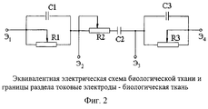
На фиг.2 приведена эквивалентная электрическая схема биологической ткани и границы раздела токовые электроды - биологическая ткань (ТЭ - БТ). Figure 2 shows the equivalent electrical circuit of biological tissue and the interface between current electrodes and biological tissue (TE - BT).
Устройство содержит генератор синусоидальных напряжений 1 с частотами 1,5 кГц, 6 кГц, 24 кГц, 96 кГц, последовательно соединенные с ним четырехканальный мультиплексор 2, широкополосный усилитель с изменяемым коэффициентом усиления 3. К выходу широкополосного усилителя с изменяемым коэффициентом усиления 3 подключен один из токовых электродов Э1 четырехконтактного зонда 4, а другой его токовый электрод Э4 подключен через резистор 13 к широкополосному усилителю 5. Выход широкополосного усилителя 5 подключен к компаратору напряжения 6 и фазовому детектору 7, соединенному с низкочастотным фильтром 8, выход которого подключен к одному входу операционного усилителя 10, к другому входу которого подключен потенциометр 9. К выходу операционного усилителя 10 подключен вход управления широкополосного усилителя с изменяемым коэффициентом усиления 3. Потенциальные электроды Э2 и Э3 четырехконтактного зонда 4 подключены к соответствующим входам повторителей напряжения 11 и 12, а их выходы соединены с фазочувствительным измерителем разности двух напряжений 14. К выходу фазочувствительного измерителя разности двух напряжений 14 подключен усилитель постоянного напряжения с двумя фиксированными коэффициентами усиления 15. Выход усилителя постоянного напряжения с двумя фиксированными коэффициентами усиления 15 соединен через аналого-цифровой преобразователь 16 с жидкокристаллическим индикатором 17. Вход управления фазочувствительного измерителя разности двух напряжений 14 подключен к выходу двухпозиционного переключателя 20. Выход компаратора напряжений 6 соединен с одним входом двухпозиционного переключателя 20 и через формирователь задержек 18 с четырехканальным мультиплексором 19, - с другим входом двухпозиционного переключателя 20.The device contains a sinusoidal voltage generator 1 with frequencies of 1.5 kHz, 6 kHz, 24 kHz, 96 kHz, a four-channel multiplexer 2 connected in series with it, a broadband amplifier with a variable gain 3. To the output of a broadband amplifier with a variable gain 3, one of current electrodes E 1 four-contact probe 4 and the other current electrode E 4 is connected through a resistor 13 to a broadband amplifier 5. The output of broadband amplifier 5 is connected to a
Устройство измерения активной и емкостной составляющих импеданса биологических тканей работает следующим образом. A device for measuring the active and capacitive components of the impedance of biological tissues works as follows.
Генератор синусоидальных напряжений 1 вырабатывает четыре строго гармонических сигнала с частотами 1,5 кГц, 6 кГц, 24 кГц и 96 кГц. Переменные напряжения с указанными частотами поступают на четырех анальный мультиплексор 2, где происходит выбор необходимой частоты для проведения измерений. С выхода мультиплексора 2, синусоидальное напряжение подается на широкополосный усилитель с изменяемым (автоматически регулируемым) коэффициентом усиления 3. The sinusoidal voltage generator 1 produces four strictly harmonic signals with frequencies of 1.5 kHz, 6 kHz, 24 kHz and 96 kHz. Alternating voltages with the indicated frequencies are supplied to four anal multiplexer 2, where the necessary frequency is selected for measurements. From the output of multiplexer 2, a sinusoidal voltage is supplied to a broadband amplifier with a variable (automatically adjustable) gain 3.
В широкополосном усилителе 3 осуществляется усиление напряжения таким образом, чтобы зондирующий ток через биологическую ткань (через крайние токовые электроды) оставался постоянной амплитуды, независимо от сопротивления биологического объекта. Регулирование коэффициента усиления широкополосного усилителя с изменяемым коэффициентом усиления 3 осуществляется за счет сигнала, снимаемого с постоянного резистора 13, включенного последовательно с токовым электродом Э4 четырехконтактного зонда 4 в цепи зондирующего тока. Падение напряжения, снимаемое с постоянного резистора 13, пропорциональное амплитуде зондирующего тока, подается на широкополосный усилитель 5.In the broadband amplifier 3, the voltage is amplified so that the probing current through the biological tissue (through the extreme current electrodes) remains constant in amplitude, regardless of the resistance of the biological object. The gain of a broadband amplifier with a variable gain 3 is controlled by a signal taken from a constant resistor 13 connected in series with the current electrode E 4 of the four-pin probe 4 in the probe current circuit. The voltage drop removed from the constant resistor 13, proportional to the amplitude of the probing current, is supplied to the broadband amplifier 5.
Усиленный сигнал с выхода широкополосного усилителя 5 поступает на компаратор напряжения 6 и фазовый детектор 7. С выхода фазового детектора 7 продетектированный сигнал подается на низкочастотный фильтр 8. Сигнал на выходе низкочастотного фильтра 8, пропорциональный величине зондирующего тока, через биологический объект сравнивается с задающим (опорным) напряжением, снимаемым с потенциометра 9. Сигнал разбаланса усиливается операционным усилителем 10 и поступает в цепь управления широкополосного усилителя с изменяемым коэффициентом усиления 3. В результате между токовыми контактами Э1 и Э4 четырехконтактного зонда 4 протекает ток заданной величины независимо от электрических свойств биологической ткани и переходных сопротивлений границы раздела электрод - биологическая ткань. Падение напряжения с поверхности биологической ткани снимается с помощью потенциальных электродов Э2 и Э3 четырехконтактного зонда 4 и подается на вход повторителя напряжения 11 и вход повторителя напряжения 12, обеспечивающих высокое входное сопротивление. С выхода повторителей 11 и 12 напряжения подаются на входы фазочувствительного измерителя разности двух напряжений 14. Управление фазочувствительным измерителем разности двух напряжений 14 осуществляется сигналом, который поступает с двухпозиционного переключателя 20. В зависимости от положения двухпозиционного переключателя 20 на выходе фазочувствительного измерителя разности двух напряжений появляется сигнал, соответствующий емкостной или активной составляющей импеданса биологического объекта. При измерении емкостной реактивной составляющей импеданса необходима задержка фазы управляющего сигнала на четверть периода, поэтому управляющий сигнал проходит через формирователь задержек 18 и четырехканальный мультиплексор 19. При измерении активной составляющей напряжения управляющий сигнал фазы поступает непосредственно с компаратора 6 на двухпозиционный переключатель 20 и затем на фазочувствительный измеритель разности двух напряжений 14. С выхода фазочувствительного измерителя разности двух напряжений 14 постоянная составляющая продетектированного сигнала поступает на усилитель постоянного напряжения 15, имеющий два фиксированных коэффициента усиления 1:1 и 1:10. Усиленное постоянное напряжение с выхода усилителя постоянного напряжения 15 подается на аналого-цифровой преобразователь 16 и затем на жидкокристаллической индикатор 17, на котором индицируется величина активного или емкостного сопротивления ткани.The amplified signal from the output of the broadband amplifier 5 is fed to the
Проведены испытания работоспособности опытного экземпляра устройства для измерения активной и емкостной составляющих импеданса биологических тканей. The performance tests of a prototype device for measuring the active and capacitive components of the impedance of biological tissues were performed.
Испытания включают калибровку прибора, установку величины зондирующего измерительного тока и проверку его стабильности при изменении внешнего сопротивления на токовых электродах, а также измерение активной и емкостной составляющих импеданса на электрической модели биологической ткани (эквивалентной электрической схеме). Tests include calibrating the device, setting the value of the probe measuring current and checking its stability when the external resistance changes on the current electrodes, as well as measuring the active and capacitive components of the impedance on an electrical model of biological tissue (equivalent to an electrical circuit).
1. Установка измерительного (зондирующего) тока. 1. Installation of measuring (probing) current.
К четырехконтактному зонду в качестве биологического объекта включается электрическая модель биологического объекта (эквивалентная электрическая схема биологической ткани), представленная на фиг.2, где:
Э1 и Э4 - токовые электроды;
Э2 и Э3 - потенциальные электроды;
С1 и R1 - моделируют электрические свойства границы раздела Э - БТ;
С3 и R3 - моделируют электрические свойства границы раздела Э - БТ;
R2 - моделирует активное сопротивление БТ;
С2 - моделирует реактивное емкостное сопротивление БТ.To a four-pin probe as a biological object, an electric model of a biological object (equivalent electrical circuit of biological tissue) is included, as shown in figure 2, where:
E 1 and E 4 - current electrodes;
E 2 and E 3 are potential electrodes;
C1 and R1 - model the electrical properties of the E – BT interface;
C3 and R3 - model the electrical properties of the E – BT interface;
R2 - simulates the active resistance of BT;
C2 - models reactive capacitive reactance of BT.
Установка измерительного зондирующего тока проводится по показаниям милливольтметра, подключенного к резистору 13 (см. блок-схему), путем изменения величины потенциометра 9. Измерительный ток устанавливают величиной 0,0001 А. The installation of the measuring probe current is carried out according to the readings of the millivoltmeter connected to the resistor 13 (see the block diagram) by changing the value of the potentiometer 9. The measuring current is set to 0.0001 A.
2. Проверка стабильности измерительного тока при возможных изменениях сопротивления биологического объекта между токовыми электродами. 2. Checking the stability of the measuring current with possible changes in the resistance of a biological object between current electrodes.
К прибору подключают эквивалентную электрическую схему (см. фиг.2). An equivalent electrical circuit is connected to the device (see FIG. 2).
Изменяют величины переменных резисторов R1 и R2 в пределах от 10 Ом до 10000 Ом. При этом величина измерительного тока практически остается постоянной в пределах точности стандартного измерительного прибора ±1%. The values of the variable resistors R1 and R2 vary from 10 ohms to 10,000 ohms. In this case, the value of the measuring current practically remains constant within the accuracy of a standard measuring device ± 1%.
3. Проверка работоспособности прибора при измерении активной составляющей импеданса. 3. Checking the operability of the device when measuring the active component of the impedance.
Двухпозиционный переключатель должен находиться в положении "R". Проверка производится подключением эквивалентной электрической схемы, представленной на фиг.2, при следующих параметрах элементов R1=R2=R3=10 кОм, С1=С2= С3=0,1 мкФ. При этом на всех частотах 1,5 кГц, 6 кГц, 24 кГц и 96 кГц показания на цифровом индикаторе остаются постоянными и составляют 10 кОм. В случае отклонения показаний цифрового индикатора от истинного значения резистора R2 (в данном случае R2=10 кОм) может быть произведена корректировка при настройке прибора. The on / off switch must be in the "R" position. The check is made by connecting the equivalent electrical circuit shown in figure 2, with the following parameters of the elements R1 = R2 = R3 = 10 kOhm, C1 = C2 = C3 = 0.1 μF. At the same time, at all frequencies of 1.5 kHz, 6 kHz, 24 kHz and 96 kHz, the readings on the digital indicator remain constant and amount to 10 kOhm. If the digital indicator deviates from the true value of the resistor R2 (in this case, R2 = 10 kOhm), an adjustment can be made when setting up the device.
4. Проверка работоспособности прибора при измерении реактивной емкостной составляющей импеданса. 4. Checking the performance of the device when measuring the reactive capacitive component of the impedance.
Двухпозиционный переключатель перевести в положение "Хс". Для проведения проверки подключают эквивалентную электрическую схему на фиг.2 при тех же параметрах элементов, то есть R1=R2=R3=10 кОм, С1=С2=С3=0,1 мкФ. Величины резистора R2 и конденсатора С2, моделирующих непосредственно электрические свойства биологической ткани, предварительно измеряли с помощью стандартного универсального L, С, R измерителя типа Е7-11 с погрешностью измерений не выше 1%.Turn the on / off switch to the "X s " position. To carry out the verification, the equivalent electric circuit in Fig. 2 is connected with the same parameters of the elements, that is, R1 = R2 = R3 = 10 kΩ, C1 = C2 = C3 = 0.1 μF. The values of resistor R2 and capacitor C2, directly simulating the electrical properties of biological tissue, were previously measured using a standard universal L, C, R meter of type E7-11 with a measurement error of no higher than 1%.
Результаты измерений реактивной, емкостной составляющей импеданса Хс на всех частотах и рассчитанные значения ![]()
![]()
Таким образом, опытный экземпляр устройства четко выделяет на гармоническом сигнале активную и емкостную составляющие импеданса с погрешностью ±1%. Thus, the prototype of the device clearly distinguishes the active and capacitive components of the impedance with an error of ± 1% on the harmonic signal.
Предложенное устройство значительно повышает точность измерений активной и емкостной составляющих импеданса биологической ткани и может быть рекомендовано для точных биофизических и медицинских исследований при диагностике различных заболеваний. The proposed device significantly improves the accuracy of measurements of the active and capacitive components of the impedance of biological tissue and can be recommended for accurate biophysical and medical studies in the diagnosis of various diseases.
Литература к заявке
1. Клиническая реография, под редакцией Б.Г. Шершнева, Киев, "Здоровье", 1977, с. 8.Application Literature
1. Clinical rheography, edited by B.G. Shershneva, Kiev, "Health", 1977, p. 8.
2. Тренчук В.В. Импедансометрия роговицы глаза. Киев, "Здоровье", 1986, с. 88. 2. Trenchuk V.V. Impedanometry of the cornea of the eye. Kiev, "Health", 1986, p. 88.
3. Прохончуков А.А., Логинова Н.К., Жижина Н.А. Функциональная диагностика в стоматологической практике. М.: "Медицина", 1980, с. 74-78. 3. Prokhonchukov A.A., Loginova N.K., Zhizhina N.A. Functional diagnostics in dental practice. M .: "Medicine", 1980, p. 74-78.
4. Мажбич Б.И. Методика раздельной графической регистрации омической и емкостной составляющих электрического сопротивления участка легочной ткани у человека. Бюл. экспер. биол. и мед.. 1964, 3, c. 121. 4. Mazhbich B.I. The technique of separate graphic registration of the ohmic and capacitive components of the electrical resistance of the lung tissue site in humans. Bull. an expert. biol. and honey .. 1964, 3, p. 121.
5. Дехтяренко П. И. Синхронное детектирование в измерительной технике, Киев, 1965, 313 с. 5. Dekhtyarenko P. I. Synchronous detection in measuring equipment, Kiev, 1965, 313 pp.
6. Кнеллер В.Ю. Автоматическое измерение составляющих комплексного сопротивления. М.-Л. "Энергия", 1967, 354 с. 6. Kneller V.Yu. Automatic measurement of the components of complex resistance. M.-L. "Energy", 1967, 354 p.
7. Гуревич М. И. , Соловьев А.И., Литовченко Л.П., Доломан Л.Б. Импедансная реоплетизмография, Киев: "Наукова думка", 1982, с.70-71. 7. Gurevich M.I., Soloviev A.I., Litovchenko L.P., Doloman L.B. Impedance reoplethysmography, Kiev: "The Science Dumka", 1982, pp. 70-71.
8. Авторское свидетельство СССР 1759402, кл. А 61 В 5/05 1990 - прототип. 8. Copyright certificate of the USSR 1759402, cl. A 61 B 5/05 1990 is a prototype.
9. Электротехнический справочник. 5 издание, под ред. П.Г. Грудинского и др., М.: "Энергия", 1974 г., с. 39. 9. Electrical reference book. 5th edition, ed. P.G. Grudinsky et al., M .: "Energy", 1974, p. 39.
Claims (1)
Priority Applications (1)
| Application Number | Priority Date | Filing Date | Title |
|---|---|---|---|
| RU2000117324/14A RU2196504C2 (en) | 2000-06-28 | 2000-06-28 | Device for measuring active and capacitive components of biological tissue impedance |
Applications Claiming Priority (1)
| Application Number | Priority Date | Filing Date | Title |
|---|---|---|---|
| RU2000117324/14A RU2196504C2 (en) | 2000-06-28 | 2000-06-28 | Device for measuring active and capacitive components of biological tissue impedance |
Publications (2)
| Publication Number | Publication Date |
|---|---|
| RU2000117324A RU2000117324A (en) | 2002-06-27 |
| RU2196504C2 true RU2196504C2 (en) | 2003-01-20 |
Family
ID=20237165
Family Applications (1)
| Application Number | Title | Priority Date | Filing Date |
|---|---|---|---|
| RU2000117324/14A RU2196504C2 (en) | 2000-06-28 | 2000-06-28 | Device for measuring active and capacitive components of biological tissue impedance |
Country Status (1)
| Country | Link |
|---|---|
| RU (1) | RU2196504C2 (en) |
Cited By (4)
| Publication number | Priority date | Publication date | Assignee | Title |
|---|---|---|---|---|
| RU2504328C1 (en) * | 2012-07-06 | 2014-01-20 | Федеральное государственное бюджетное образовательное учреждение высшего профессионального образования "Юго-Западный государственный университет" (ЮЗГУ) | Device for controlling anisotropy of electric conductivity of biotissues |
| RU2509531C1 (en) * | 2012-07-04 | 2014-03-20 | Федеральное государственное бюджетное образовательное учреждение высшего профессионального образования "Тамбовский государственный технический университет" ФГБОУ ВПО ТГТУ | Method for determining bioobject impedance components |
| RU2522949C1 (en) * | 2012-12-17 | 2014-07-20 | Общество С Ограниченной Ответственностью "Хилби" | Device for measuring electric parameters of individual's body area |
| CN112914576A (en) * | 2020-09-30 | 2021-06-08 | 世耳医疗科技(上海)有限公司 | Human body bioelectricity detection circuit, detection system and detection method |
-
2000
- 2000-06-28 RU RU2000117324/14A patent/RU2196504C2/en not_active IP Right Cessation
Cited By (5)
| Publication number | Priority date | Publication date | Assignee | Title |
|---|---|---|---|---|
| RU2509531C1 (en) * | 2012-07-04 | 2014-03-20 | Федеральное государственное бюджетное образовательное учреждение высшего профессионального образования "Тамбовский государственный технический университет" ФГБОУ ВПО ТГТУ | Method for determining bioobject impedance components |
| RU2504328C1 (en) * | 2012-07-06 | 2014-01-20 | Федеральное государственное бюджетное образовательное учреждение высшего профессионального образования "Юго-Западный государственный университет" (ЮЗГУ) | Device for controlling anisotropy of electric conductivity of biotissues |
| RU2522949C1 (en) * | 2012-12-17 | 2014-07-20 | Общество С Ограниченной Ответственностью "Хилби" | Device for measuring electric parameters of individual's body area |
| CN112914576A (en) * | 2020-09-30 | 2021-06-08 | 世耳医疗科技(上海)有限公司 | Human body bioelectricity detection circuit, detection system and detection method |
| CN112914576B (en) * | 2020-09-30 | 2024-03-22 | 世耳医疗科技(上海)有限公司 | Human body bioelectricity detection circuit, detection system and detection method |
Similar Documents
| Publication | Publication Date | Title |
|---|---|---|
| JP3907353B2 (en) | Bioimpedance measurement device | |
| Ackmann | Complex bioelectric impedance measurement system for the frequency range from 5 Hz to 1 MHz | |
| US4692685A (en) | Electrical measuring apparatus, and methods for determining the condition or identity of biological material | |
| EP0417796A2 (en) | Hematocrit measuring instrument | |
| WO2006074092A1 (en) | High precision voltage source for electrical impedance tomography | |
| JPH1014898A (en) | Bioelectric impedance measuring device | |
| WO2011060497A1 (en) | Signal distribution for patient-electrode measurements | |
| Noveletto et al. | Analog front-end for the integrated circuit AD5933 used in electrical bioimpedance measurements | |
| JP2000060878A (en) | Root apex position detector | |
| Al-Hatib | Patient-instrument connection errors in bioelectrical impedance measurement | |
| RU2196504C2 (en) | Device for measuring active and capacitive components of biological tissue impedance | |
| JP3692014B2 (en) | A system to compensate for pressure and temperature effects | |
| Torrents et al. | Compensation of impedance meters, when using an external front-end amplifier | |
| Kamp et al. | Technological basis of EEG recording | |
| JP2003116803A (en) | Electric characteristic measuring system | |
| Jones et al. | Constraints on tetrapolar tissue impedance measurements | |
| JP4671467B2 (en) | Impedance measuring device | |
| SU1759402A1 (en) | Device for measuring active and reactive components of biological tissue impedance | |
| Margo et al. | Four electrode embedded bioimpedance measurement system | |
| Dušek et al. | Designing a cost-effective multiplexer for electrical impedance tomography | |
| AU2012372049B2 (en) | Method for controlling electrodes for bio-impedance measurements and apparatus for bio-impedance measurements | |
| RU2462185C1 (en) | Device for measuring impedance of biological media | |
| RU2504328C1 (en) | Device for controlling anisotropy of electric conductivity of biotissues | |
| WO2006021891A1 (en) | Apical constriction locator | |
| Mungall et al. | Measurement of the dielectric properties of blood |
Legal Events
| Date | Code | Title | Description |
|---|---|---|---|
| MM4A | The patent is invalid due to non-payment of fees |
Effective date: 20020629 |