RU2196305C2 - Facility determining mass of helicopter in horizontal flight - Google Patents
Facility determining mass of helicopter in horizontal flight Download PDFInfo
- Publication number
- RU2196305C2 RU2196305C2 RU2001102624A RU2001102624A RU2196305C2 RU 2196305 C2 RU2196305 C2 RU 2196305C2 RU 2001102624 A RU2001102624 A RU 2001102624A RU 2001102624 A RU2001102624 A RU 2001102624A RU 2196305 C2 RU2196305 C2 RU 2196305C2
- Authority
- RU
- Russia
- Prior art keywords
- blade
- helicopter
- rotor
- distance
- input
- Prior art date
Links
Images

Landscapes
- Testing Or Calibration Of Command Recording Devices (AREA)
Abstract
Description
Изобретение относится к классу измерительной техники и может быть использовано в информационно-измерительных системах и системах управления вертолетом. The invention relates to the class of measuring equipment and can be used in information-measuring systems and helicopter control systems.
Известно устройство (Arnoltbmil, Poits Herman, Pichter Peter. Регулирующее устройство несущего винта вертолета. Патент ФРГ, МКИ В 64 D 27/26, 1481601, заявлено 3.01.66 г., опубл. 8.03.73 г.) - [1] для регулировки тяги несущего винта вертолета, содержащее тензометрические датчики упругих деформаций, расположенные на каждой лопасти в разных точках. Сигналы с датчиков, соответствующие напряжениям изгиба лопасти и зависящие от подъемной силы винта, подаются на вычислительное устройство. Недостатком устройства является значительная погрешность измерения тяги несущего винта вертолета за счет сильного влияния изменения температуры окружающей среды на работу тензометрических датчиков. A device is known (Arnoltbmil, Poits Herman, Pichter Peter. Regulating device of the rotor of a helicopter. Germany patent, MKI B 64 D 27/26, 1481601, claimed 3.01.66, publ. 8.03.73) - [1] for adjusting the rotor thrust of the helicopter, containing strain gauges for elastic deformation located on each blade at different points. The signals from the sensors, corresponding to the bending stresses of the blades and depending on the lifting force of the screw, are fed to the computing device. The disadvantage of this device is the significant error in measuring the thrust of the rotor of the helicopter due to the strong influence of changes in ambient temperature on the operation of strain gauge sensors.
Известное устройство для определения веса вертолета с несущим винтом над фюзеляжем, образованным несколькими лопастями, установленными в ступице на вращающемся валу, приводящим лопасти во вращение, содержит датчики частоты вращения несущего винта и продольной скорости движения, согласующее устройство, вычислитель и индикатор, причем выход согласующего устройства соединен со входом вычислителя, подключенного к индикатору (США, патент 5229956, 20.07.1993 г., G 01 G 9/00, опубл. РЖ ИСМ. Вып. 82, 1, 1995 г.) - [2]. A known device for determining the weight of a helicopter with a rotor above the fuselage, formed by several blades mounted in a hub on a rotating shaft, leading the blades to rotate, contains sensors of the rotor speed and longitudinal speed, matching device, calculator and indicator, and the output of the matching device connected to the input of the calculator connected to the indicator (US patent 5229956, 07.20.1993, G 01 G 9/00, publ. RZH ISM.
Это устройство выбрано для сравнительного анализа с предлагаемым техническим решением. This device is selected for comparative analysis with the proposed technical solution.
Недостатком данного устройства является недостаточная точность определения массы вертолета в горизонтальном полете. The disadvantage of this device is the lack of accuracy in determining the mass of the helicopter in horizontal flight.
Изобретение решает задачу повышения точности определения массы вертолета в горизонтальном полете за счет реализации наиболее совершенного способа определения статического давления на вертолете. The invention solves the problem of increasing the accuracy of determining the mass of a helicopter in horizontal flight by implementing the most advanced method for determining the static pressure on a helicopter.
Это достигается тем, что в устройство для определения массы вертолета в горизонтальном полете, содержащее датчики частоты вращения несущего винта и продольной скорости движения, согласующее устройство, вычислитель и индикатор, причем выход согласующего устройства соединен со входом вычислителя, подключенного к индикатору, введены три интегратора, преобразователь частоты в напряжение, датчик температуры воздуха за бортом и три датчика давления, каждый из которых подсоединен к своему дренажному отверстию на поверхности лопасти, которые расположены в одном сечении лопасти на расстоянии r=0,7R от оси вращения несущего винта, где R - радиус несущего винта, при этом первое дренажное отверстие расположено на нагнетающей стороне лопасти на расстоянии ~ 0,4 хорды от передней кромки, второе - на засасывающей стороне лопасти на том же расстоянии, а третье - на нагнетающей стороне лопасти на расстоянии ~ 0,6 хорды от передней кромки, при этом каждый датчик давления соединен со входом своего интегратора, входы управления которых и вход преобразователя частоты в напряжение соединены с датчиком частоты вращения несущего винта, выходы интеграторов, преобразователя частоты в напряжение, датчиков продольной скорости движения и температуры воздуха за бортом подключены ко входам согласующего устройства. This is achieved by the fact that in the device for determining the mass of the helicopter in horizontal flight, containing sensors of the rotor speed and longitudinal speed, a matching device, a calculator and an indicator, the output of the matching device connected to the input of the calculator connected to the indicator, three integrators are introduced, a frequency to voltage converter, an air temperature sensor overboard and three pressure sensors, each of which is connected to its drainage hole on the surface of the blade, which the blades are located in one section at a distance r = 0.7R from the rotor axis of rotation of the rotor, where R is the radius of the rotor, with the first drainage hole located on the discharge side of the blade at a distance of ~ 0.4 chords from the leading edge, the second at the suction side of the blade at the same distance, and the third on the discharge side of the blade at a distance of ~ 0.6 chords from the leading edge, with each pressure sensor connected to the input of its integrator, the control inputs of which and the input of the frequency converter to the voltage are connected to the sensor com rotor speed, integrators outputs the frequency-voltage converter, the longitudinal velocity sensors and temperature overboard connected to the inputs of the matching device.
Для пояснения сущности изобретения на фиг.1 представлена блок-схема устройства, где:
1, 2, 3 - датчики давления, воспринимающие давления соответственно в первой, второй и третьей точках на поверхности лопасти;
4, 5, 6 - интеграторы;
7 - датчик частоты вращения несущего винта;
8 - преобразователь частоты в напряжение;
9 - датчик продольной скорости движения вертолета;
10 - датчик температуры воздуха за бортом;
11 - согласующее устройство;
12 - вычислитель;
13 - индикатор.To clarify the invention, figure 1 presents a block diagram of a device, where:
1, 2, 3 - pressure sensors that sense pressure, respectively, at the first, second and third points on the surface of the blade;
4, 5, 6 - integrators;
7 - rotor speed sensor;
8 - frequency to voltage converter;
9 - the sensor of the longitudinal speed of the helicopter;
10 - air temperature sensor overboard;
11 - matching device;
12 - calculator;
13 - indicator.
В устройстве каждый из датчиков давления 1, 2, 3 подключен к своему дренажному отверстию на поверхности лопасти, которые расположены в одном сечении лопасти на расстоянии r=0,7R, при этом первое дренажное отверстие расположено на нагнетающей стороне лопасти на расстоянии ~0,4 хорды от передней кромки, второе - на засасывающей стороне лопасти на том же расстоянии, а третье - на нагнетающей стороне лопасти на расстоянии ~0,6 хорды от передней кромки. Каждый датчик давления 1, 2, 3 соединен со входом своего интегратора 4, 5, 6, входы управления которых и вход преобразователя частоты в напряжение 8 соединены с датчиком частоты вращения 7 несущего винта. Выходы интеграторов 4, 5, 6, преобразователя частоты в напряжение 8, датчиков продольной скорости движения 9 и температуры воздуха за бортом 10 подключены ко входам согласующего устройства 11, выход которого соединен с вычислителем 12, подключенным к индикатору 13. In the device, each of the
Устройство работает следующим образом. Сигналы с датчиков давления 1, 2, 3 пропорциональны давлениям P1, Р2 и Р3, снимаемым в точках поверхности лопасти в сечении r=0,7R, расположение которых представлено на фиг.2, где b - хорда сечения несущего винта (НВ), поступают на интеграторы 4, 5 и 6, на входы управления которых подается также сигнал с датчика частоты вращения несущего винта вертолета. Интеграторы 4, 5 и 6 вырабатывают сигналы, пропорциональные осредненным за один оборот несущего винта значениям давлений ![]()
![]()
где τ - период вращения НВ.The device operates as follows. The signals from the ![]()
![]()
where τ is the period of rotation of the HB.
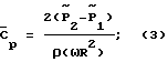
Одновременно сигнал с датчика частоты вращения 7 НВ поступает на вход преобразователя частоты в напряжение 8. Далее выходные сигналы интеграторов 4, 5 и 6, преобразователя частоты в напряжение 8, датчика продольной скорости движения вертолета 9 и датчика температуры воздуха за бортом 10 поступают на согласующее устройство 11, которое преобразует их в цифровые коды, поступающие на вычислитель 12. Вычислитель 12 вычисляет величину массы вертолета и полученный результат отображается на индикаторе 13. Вычислитель 12 реализует следующий алгоритм:
![]()
![]()
![]()
где μ - коэффициент режима работы НВ;
Vx - продольная скорость движения вертолета;
ω - частота вращения НВ;
R - радиус НВ вертолета;
М - среднее за один оборот НВ значение числа Маха на конце лопасти;
a - скорость звука за бортом;
ρ - плотность воздуха за бортом;
![]()
Ст - коэффициент тяги НВ вертолета;
m - масса вертолета;
g - ускорение свободного падения.At the same time, the signal from the speed sensor 7 HB is fed to the input of the frequency converter to voltage 8. Next, the output signals of the integrators 4, 5 and 6, the frequency converter to voltage 8, the longitudinal velocity sensor of the helicopter 9 and the air temperature sensor overboard 10 are fed to the matching device 11, which converts them into digital codes supplied to the computer 12. The computer 12 calculates the mass of the helicopter and the result is displayed on the indicator 13. The computer 12 implements the following algorithm:
![]()
![]()
![]()
where μ is the coefficient of the HB operation mode;
V x - the longitudinal speed of the helicopter;
ω is the rotational speed of the HB;
R is the radius of the HB helicopter;
M is the average for one revolution of the HB value of the Mach number at the end of the blade;
a is the speed of sound overboard;
ρ is the air density overboard;
![]()
With t - thrust coefficient of the NV helicopter;
m is the mass of the helicopter;
g is the acceleration of gravity.
Скорость звука и плотность воздуха за бортом вычисляются по формулам (Акимов А. И. , Берестов А.М., Михеев Р.А. Летные испытания вертолетов. М., Машиностроение, 1980) - [3]. The speed of sound and the density of air overboard are calculated by the formulas (Akimov A.I., Berestov A.M., Mikheev R.A. Flight tests of helicopters. M., Mechanical Engineering, 1980) - [3].
![]()
![]()
где Pст - величина статического давления за бортом;
to - температура воздуха за бортом. ![]()
![]()
where P article - the value of the static pressure overboard;
t o - air temperature overboard.
В свою очередь величина статического давления Рст вычисляется через значения осредненных за один оборот НВ давлений ![]()
![]()
![]()
где k1, k2, k3 - константы, определенные для конкретного профиля лопасти и места расположения точек съема давлений P1, Р2 и P3 на ее поверхности. ![]()
where k 1 , k 2 , k 3 are constants defined for a particular profile of the blade and the location of the pressure release points P 1 , P 2 and P 3 on its surface.
Функциональная зависимость (4) коэффициента тяги HВ Ст от коэффициента режима работы НВ μ, числа Маха М на конце лопасти и коэффициента ![]()
![]()
Оценка точности определения массы вертолета в полете с помощью предлагаемого устройства показала, что если инструментальная погрешность измерения давления составляет ΔР= 30 Па, погрешность измерения продольной скорости движения вертолета оценивается величиной ΔVx=5 км/ч, инструментальная погрешность измерения частоты вращения НВ составляет Δω ==0,1 рад/с, а температура воздуха за бортом определяется с точностью Δto=1o, то относительная погрешность определения массы вертолета в полете не превышает 1-2%.Evaluation of the accuracy of determining the mass of the helicopter in flight using the proposed device showed that if the instrumental error in the pressure measurement is ΔР = 30 Pa, the error in measuring the longitudinal velocity of the helicopter is estimated at ΔV x = 5 km / h, the instrumental error in measuring the rotational speed of HB is Δω = = 0.1 rad / s, and the air temperature overboard is determined with an accuracy of Δt o = 1 o , then the relative error in determining the mass of the helicopter in flight does not exceed 1-2%.
Заявленное устройство может быть реализовано с использованием серийно выпускаемых комплектующих изделий. The claimed device can be implemented using commercially available components.
Источники информации
1. В качестве датчиков давления могут быть использованы любые стандартные датчики, вырабатывающие электрический сигнал, пропорциональный давлению воздуха (Браславский Д.А. Приборы и датчики летательных аппаратов. М., Машиностроение, 1970 г., 392 с.).Sources of information
1. Any standard sensors that generate an electrical signal proportional to air pressure can be used as pressure sensors (D. Braslavsky. Instruments and sensors of aircraft. M., Mechanical Engineering, 1970, 392 p.).
2. Преобразователь частоты в напряжение 8 и интеграторы 4, 5 и 6 могут быть выполнены по известным схемам (Титце У., Шенк К. Полупроводниковая схемотехника. М., Мир, 1982г., 512 с.). 2. The frequency to voltage converter 8 and the integrators 4, 5 and 6 can be made according to known schemes (Titz U., Schenk K. Semiconductor circuitry. M., Mir, 1982, 512 pp.).
3. Датчик продольной скорости 9 - приемник воздушного давления, например, ПВД-5 с измерительным преобразователем типа ИКД27ДА или ИКД27ДФ. 3. The longitudinal velocity sensor 9 is an air pressure receiver, for example, PVD-5 with a measuring transducer of the type IKD27DA or IKD27DF.
4. Датчик частоты вращения несущего винта 7 - штатный датчик типа Д-1. 4. The rotor speed sensor 7 - a standard sensor type D-1.
5. Датчик температуры воздуха за бортом 10 - датчик типа П-5 с измерительным преобразователем. 5. Air temperature sensor overboard 10 - type P-5 sensor with a measuring transducer.
6. Согласующее устройство 11 - может быть использован модуль аналогового типа 15КА-60/8-10. 6. Matching device 11 - an analog type module 15KA-60 / 8-10 can be used.
7. Вычислитель 12 - может быть использована бортовая ЭВМ, однокристальная микро-ЭВМ серии 180б, 1813 и т.п. 7. Computer 12 — an on-board computer, a single-chip micro-computer of a series 180b, 1813, etc., can be used.
8. Индикатор 13 - цифровой вольтметр, например, типа КАЦ 202, АЛС-324, на которых величина массы вертолета отображается непосредственно в цифрах. 8. Indicator 13 - a digital voltmeter, for example, type KAC 202, ALS-324, on which the mass of the helicopter is displayed directly in numbers.
Применение заявленного устройства по сравнению с прототипом позволяет решить задачу повышения точности определения массы вертолета в полете. The use of the claimed device in comparison with the prototype allows us to solve the problem of increasing the accuracy of determining the mass of the helicopter in flight.
Claims (1)
Priority Applications (1)
| Application Number | Priority Date | Filing Date | Title |
|---|---|---|---|
| RU2001102624A RU2196305C2 (en) | 2001-01-29 | 2001-01-29 | Facility determining mass of helicopter in horizontal flight |
Applications Claiming Priority (1)
| Application Number | Priority Date | Filing Date | Title |
|---|---|---|---|
| RU2001102624A RU2196305C2 (en) | 2001-01-29 | 2001-01-29 | Facility determining mass of helicopter in horizontal flight |
Publications (1)
| Publication Number | Publication Date |
|---|---|
| RU2196305C2 true RU2196305C2 (en) | 2003-01-10 |
Family
ID=20245343
Family Applications (1)
| Application Number | Title | Priority Date | Filing Date |
|---|---|---|---|
| RU2001102624A RU2196305C2 (en) | 2001-01-29 | 2001-01-29 | Facility determining mass of helicopter in horizontal flight |
Country Status (1)
| Country | Link |
|---|---|
| RU (1) | RU2196305C2 (en) |
-
2001
- 2001-01-29 RU RU2001102624A patent/RU2196305C2/en active
Similar Documents
| Publication | Publication Date | Title |
|---|---|---|
| EP1172656B1 (en) | Rotational direction detecting | |
| US4590475A (en) | Stall avoidance system for aircraft | |
| EP0597899B1 (en) | Angle of attack sensor using inverted ratio of pressure differentials | |
| DE59803204D1 (en) | METHOD FOR MEASURING THE REVOLUTION OF A MOTOR VEHICLE WHEEL AND AIR PRESSURE CONTROL SYSTEM FOR A MOTOR VEHICLE | |
| US11650134B2 (en) | Determining tread depth using data from a tire-mounted sensor | |
| EP0502811B1 (en) | Helicopter weight measurement | |
| JP2004037255A (en) | Method and apparatus for estimating mass of vehicle, and method and apparatus for estimating gradient using the method | |
| JPH0668498B2 (en) | Air flow measuring device | |
| JP3860264B2 (en) | Method and apparatus for measuring airspeed of a rotorcraft | |
| US20120072130A1 (en) | Method of measuring torque and torque measuring system for said method | |
| JPH02105023A (en) | Method and device for weighing car | |
| RU2196305C2 (en) | Facility determining mass of helicopter in horizontal flight | |
| CA2472292A1 (en) | Process and apparatus for monitoring the validity of speed data for an aircraft and speed-data generating system having such an apparatus | |
| US7461548B2 (en) | Method and a device for measuring the speed of an aircraft, in particular a rotorcraft at low speed | |
| CN109159787A (en) | A kind of electric car tire attachment stable state real-time detecting system and method | |
| EP0335045A1 (en) | Flow measurement device utilizing force transducers | |
| RU168214U1 (en) | Strap-on integrated inertial heading vertical | |
| US4821581A (en) | Method and apparatus for the continuous measuring of bulk material passing over a measuring wheel | |
| US5874673A (en) | Air speed and direction indicating system for rotary winged aircraft | |
| WO2018046136A1 (en) | Estimation of absolute wheel roll radii and estimation of vertical compression value | |
| RU86752U1 (en) | HELICOPTER AIR SIGNAL SYSTEM | |
| CN110132490B (en) | Dynamic balance detection system for wheels of running vehicle | |
| RU58719U1 (en) | HELICOPTER SPEED METER | |
| US6938472B2 (en) | Static pressure calculation from dynamic pressure for rotary air-data system and methodology therefor | |
| CN100387937C (en) | Electronic turbine flowmeter for gas |