RU2194373C1 - Power supply circuit of filament lamps in luminaire - Google Patents
Power supply circuit of filament lamps in luminaire Download PDFInfo
- Publication number
- RU2194373C1 RU2194373C1 RU2001122775/09A RU2001122775A RU2194373C1 RU 2194373 C1 RU2194373 C1 RU 2194373C1 RU 2001122775/09 A RU2001122775/09 A RU 2001122775/09A RU 2001122775 A RU2001122775 A RU 2001122775A RU 2194373 C1 RU2194373 C1 RU 2194373C1
- Authority
- RU
- Russia
- Prior art keywords
- power supply
- incandescent lamps
- lamps
- wire
- lamp
- Prior art date
Links
- 238000005286 illumination Methods 0.000 abstract description 2
- 239000000126 substance Substances 0.000 abstract 1
- 230000004907 flux Effects 0.000 description 6
- 238000004804 winding Methods 0.000 description 4
- 238000002485 combustion reaction Methods 0.000 description 2
- 238000004020 luminiscence type Methods 0.000 description 2
- 230000007935 neutral effect Effects 0.000 description 2
- 238000010586 diagram Methods 0.000 description 1
Images


Classifications
-
- H—ELECTRICITY
- H05—ELECTRIC TECHNIQUES NOT OTHERWISE PROVIDED FOR
- H05B—ELECTRIC HEATING; ELECTRIC LIGHT SOURCES NOT OTHERWISE PROVIDED FOR; CIRCUIT ARRANGEMENTS FOR ELECTRIC LIGHT SOURCES, IN GENERAL
- H05B39/00—Circuit arrangements or apparatus for operating incandescent light sources
- H05B39/04—Controlling
- H05B39/041—Controlling the light-intensity of the source
-
- H—ELECTRICITY
- H05—ELECTRIC TECHNIQUES NOT OTHERWISE PROVIDED FOR
- H05B—ELECTRIC HEATING; ELECTRIC LIGHT SOURCES NOT OTHERWISE PROVIDED FOR; CIRCUIT ARRANGEMENTS FOR ELECTRIC LIGHT SOURCES, IN GENERAL
- H05B39/00—Circuit arrangements or apparatus for operating incandescent light sources
- H05B39/04—Controlling
- H05B39/06—Switching arrangements, e.g. from series operation to parallel operation
-
- Y—GENERAL TAGGING OF NEW TECHNOLOGICAL DEVELOPMENTS; GENERAL TAGGING OF CROSS-SECTIONAL TECHNOLOGIES SPANNING OVER SEVERAL SECTIONS OF THE IPC; TECHNICAL SUBJECTS COVERED BY FORMER USPC CROSS-REFERENCE ART COLLECTIONS [XRACs] AND DIGESTS
- Y02—TECHNOLOGIES OR APPLICATIONS FOR MITIGATION OR ADAPTATION AGAINST CLIMATE CHANGE
- Y02B—CLIMATE CHANGE MITIGATION TECHNOLOGIES RELATED TO BUILDINGS, e.g. HOUSING, HOUSE APPLIANCES OR RELATED END-USER APPLICATIONS
- Y02B20/00—Energy efficient lighting technologies, e.g. halogen lamps or gas discharge lamps
Landscapes
- Circuit Arrangement For Electric Light Sources In General (AREA)
Abstract
Description
Изобретение относится к светотехнике, в частности к светильникам с регулируемым световым потоком. The invention relates to lighting equipment, in particular to lamps with adjustable luminous flux.
Известна электрическая схема питания ламп накаливания светильника, содержащая диоды, включенные последовательно с соответствующими группами ламп, объединенных общей шиной, два выключателя и источник питания переменного напряжения, соединенный одним полюсом с катодом первого и анодом второго диодов (авт. свид. СССР 1221766, Н 05 В 39/00, опубл. 1986). Первый выключатель соединен с анодом первого и катодом второго диодов и установлен в электрической цепи между группами ламп. Второй выключатель установлен в электрической цепи между общей шиной и вторым полюсом источника питания. Электрическая схема питания обеспечивает работу светильника в двух режимах с максимальным и уменьшенным световым потоком. Режим максимального светового потока соответствует замкнутому состоянию обоих выключателей. При этом к обоим группам ламп накаливания подведены оба полупериода от источника переменного напряжения через первый и второй диоды. Режим уменьшенного светового потока соответствует разомкнутому первому и замкнутому второму выключателям. Ток проходит в один полупериод через первый диод и первую группу ламп накаливания, а во второй полупериод через второй диод и вторую группу ламп накаливания. Все лампы накаливания при этом светят в половину накала. A known electrical circuit for supplying incandescent lamps containing diodes connected in series with corresponding groups of lamps connected by a common bus, two switches and an AC voltage source connected to the cathode of the first and the anode of the second diodes by one pole (ed. Certificate. USSR 1221766, H 05 B 39/00, publ. 1986). The first switch is connected to the anode of the first and the cathode of the second diode and is installed in an electric circuit between groups of lamps. The second switch is installed in the electrical circuit between the common bus and the second pole of the power source. The power supply circuit provides the luminaire in two modes with maximum and reduced luminous flux. The maximum light output corresponds to the closed state of both switches. In this case, both half-periods from the AC voltage source through the first and second diodes are connected to both groups of incandescent lamps. The reduced light output mode corresponds to the open first and closed second switches. The current flows in one half-cycle through the first diode and the first group of incandescent lamps, and in the second half-cycle through the second diode and the second group of incandescent lamps. All incandescent lamps shine in half.
Недостатком известной электрической схемы питания является малое количество (два) режимов работы светильника. A disadvantage of the known electrical power circuit is a small number (two) of lamp operating modes.
Наиболее близким к предлагаемому по совокупности признаков и достигаемому техническому результату является принятая за прототип известная люстра с регулируемым световым потоком, описанная в авт. свид. СССР 1089349, Н 05 В 39/06, опубл. 1984. Люстра содержит четыре лампы накаливания, объединенные в две параллельно соединенные группы. Каждая группа выполнена в виде цепочки из двух последовательно соединенных ламп. Одна точка параллельного соединения двух групп ламп накаливания соединена с нулевым проводом однофазной сети питания через первую контактную пару двухклавишного выключателя. В люстре установлено реле с тремя группами нормально замкнутых и нормально разомкнутых контактов. Обмотка реле подсоединена к фазному проводу и через вторую контактную пару двухклавишного выключателя к нулевому проводу. Вторая точка параллельного соединения двух групп ламп накаливания соединена со средним контактом первой группы контактов реле. Нормально замкнутый и нормально разомкнутый контакты первой группы контактов реле подсоединены соответственно к первому и второму выводам обмотки реле. Средние точки каждой цепочки последовательно соединенных ламп накаливания подключены к средним контактам соответственно второй и третьей групп контактов реле, причем нормально разомкнутые контакты этих групп подсоединены к фазному проводу. Closest to the proposed combination of features and the achieved technical result is the well-known chandelier with an adjustable luminous flux adopted as a prototype, described in ed. testimonial. USSR 1089349, H 05 B 39/06, publ. 1984. A chandelier contains four incandescent lamps, combined in two parallel connected groups. Each group is made in the form of a chain of two series-connected lamps. One point of parallel connection of two groups of incandescent lamps is connected to the neutral wire of a single-phase power supply network through the first contact pair of a two-gang switch. A relay with three groups of normally closed and normally open contacts is installed in the chandelier. The relay winding is connected to the phase wire and through the second contact pair of the two-gang switch to the neutral wire. The second point of parallel connection of two groups of incandescent lamps is connected to the middle contact of the first group of relay contacts. Normally closed and normally open contacts of the first group of relay contacts are connected respectively to the first and second terminals of the relay winding. The midpoints of each chain of series-connected incandescent lamps are connected to the middle contacts of the second and third groups of relay contacts, respectively, and the normally open contacts of these groups are connected to the phase wire.
При замыкании только первой контактной пары двухклавишного выключателя фазная разность потенциалов прикладывается ко всем лампам накаливания, включенным по параллельно-последовательной схеме. При этом осуществляется режим сумеречного освещения, так как к каждой из четырех ламп накаливания подводится половина фазного напряжения. При замыкании только второй контактной пары двухклавишного выключателя на обмотку реле поступает фазное напряжение, в результате чего осуществляется коммутация цепей питания ламп накаливания и обеспечивается режим горения в полный накал двух ламп накаливания. Две другие лампы накаливания при этом не горят. При замыкании одновременно первой и второй контактных пар двухклавишного выключателя разность потенциалов на каждой лампе накаливания становится равной фазному напряжению, в результате чего осуществляется режим горения всех четырех ламп накаливания в полный накал. When only the first contact pair of the two-gang switch is closed, the phase potential difference is applied to all incandescent lamps switched on in parallel-serial circuit. In this case, the twilight lighting mode is implemented, since half of the phase voltage is applied to each of the four incandescent lamps. When only the second contact pair of the two-gang switch is closed, phase voltage is applied to the relay winding, as a result of which the power supply circuits of the incandescent lamps are switched on and the combustion mode is fully heated for two incandescent lamps. The other two incandescent lamps do not light up. When the first and second contact pairs of the two-gang switch are closed at the same time, the potential difference on each incandescent lamp becomes equal to the phase voltage, as a result of which the combustion mode of all four incandescent lamps in full glow is carried out.
Люстра с регулируемым световым потоком имеет три режима работы, что расширяет ее функциональные возможности. The chandelier with adjustable luminous flux has three modes of operation, which expands its functionality.
Недостаток люстры состоит в ее конструктивной сложности вследствие наличия реле с обмоткой, питания и тремя группами нормально замкнутых и нормально разомкнутых контактов, наличия большого количества соединительных проводов и точек соединения. The disadvantage of the chandelier is its structural complexity due to the presence of a relay with a winding, power and three groups of normally closed and normally open contacts, the presence of a large number of connecting wires and connection points.
Задача изобретения состоит в том, чтобы конструктивно упростить светильник с регулируемым световым потоком при обеспечении трех режимов его работы со свечением всех ламп накаливания в полный накал или в половину накала, а также свечением части ламп накаливания в полный накал. The objective of the invention is to constructively simplify a luminaire with an adjustable luminous flux while providing three modes of its operation with the luminescence of all incandescent lamps in full or half incandescence, as well as the illumination of part of incandescent lamps in full incandescence.
Поставленная задача решается тем, что светильник с регулируемым световым потоком содержит параллельно соединенные первую и вторую лампы накаливания, а также первую и вторую контактные пары для подключения ламп накаливания к проводам сети питания. Точка параллельного соединения ламп накаливания соединена со вторым проводом сети питания через первую контактную пару. Светильник дополнительно содержит третью контактную пару, включенную между первой лампой накаливания и вторым проводом сети. Вторая контактная пара включена между первой лампой накаливания и первым проводом сети питания. Кроме того вторая и третья контактные пары имеют общий подвижный контакт, соединенный с первой лампой накаливания, установленный с возможностью подключения к первому или второму проводам сети питания. The problem is solved in that the lamp with an adjustable luminous flux contains parallel connected first and second incandescent lamps, as well as first and second contact pairs for connecting incandescent lamps to the wires of the power network. The parallel connection point of incandescent lamps is connected to the second wire of the power supply network through the first contact pair. The lamp further comprises a third contact pair included between the first incandescent lamp and the second network wire. A second contact pair is connected between the first incandescent lamp and the first wire of the power supply. In addition, the second and third contact pairs have a common movable contact connected to the first incandescent lamp, installed with the ability to connect to the first or second wires of the power network.
Три контактные пары, из которых первая установлена между точкой параллельного соединения ламп накаливания и вторым проводом сети питания, вторая - между первой лампой накаливания и первым проводом сети питания, а третья - между первой лампой накаливания и вторым проводом сети питания, обеспечивают работу светильника в трех режимах свечения. Three contact pairs, the first of which is installed between the point of parallel connection of incandescent lamps and the second wire of the power supply network, the second - between the first incandescent lamp and the first wire of the power supply network, and the third - between the first incandescent lamp and the second wire of the power supply network, provide the lamp in three light modes.
Использование в светильнике только трех контактных пар с малым количеством соединительных проводов и точек соединения для обеспечения трех режимов свечения позволяет конструктивно упростить его, повысить надежность работы и удобство эксплуатации. The use of only three contact pairs with a small number of connecting wires and connection points in the luminaire to provide three luminescence modes makes it possible to constructively simplify it, increase reliability and ease of use.
Общий подвижный контакт второй и третьей контактных пар дополнительно упрощает светильник и позволяет использовать двухклавишный выключатель для управления тремя указанными режимами работы светильника. The common movable contact of the second and third contact pairs further simplifies the luminaire and allows the use of a two-gang switch to control the three indicated operating modes of the luminaire.
Светильник с тремя режимами работы удобен при использовании в музеях, выставочных и концертных залах, залах ожидания и других общественных помещениях, а также в жилых и производственных помещениях, на открытых площадках. The lamp with three operating modes is convenient when used in museums, exhibition and concert halls, waiting rooms and other public places, as well as in residential and industrial premises, in open areas.
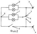
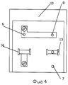
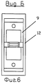
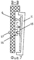
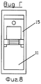
Примеры осуществления изобретения представлены на чертежах, где на фиг.1 изображена электрическая схема светильника с двумя лампами накаливания; на фиг. 2 - то же, с четырьмя лампами накаливания; на фиг.3 - двухклавишный переключатель, вид спереди; на фиг.4 - переключатель при снятых клавишах; на фиг. 5 - сечение А-А; на фиг.6 - вид Б; на фиг.7 - сечение В-В; на фиг.8 - вид Г. Examples of the invention are presented in the drawings, in which Fig. 1 shows an electrical diagram of a lamp with two incandescent lamps; in FIG. 2 - the same with four incandescent lamps; figure 3 - two-key switch, front view; figure 4 is a switch with the keys removed; in FIG. 5 - section aa; figure 6 is a view of B; figure 7 - section bb; Fig.8 is a view of G.
Светильник содержит параллельно соединенные первую 1 и вторую 2 лампы накаливания или группы первых 1 и вторых 2 ламп накаливания, подключенные к первому 3 и второму 4 проводам сети питания. Точка 5 параллельного соединения ламп накаливания соединена со вторым 4 проводом сети питания через первую 6 контактную пару. Между первой 1 лампой накаливания и первым 3 проводом сети питания включена вторая 7 контактная пара. Между первой 1 лампой накаливания и вторым 4 проводом сети питания включена третья 8 контактная пара. Вторая 7 и третья 8 контактные пары имеют общий подвижный контакт 9, установленный с возможностью подключения к первому 3 или второму 4 проводам сети питания. Первая 6, вторая 7 и третья 8 контактные пары размещены в двухклавишном переключателе 10, в котором клавиша 11 служит для замыкания и размыкания первой 6 контактной пары, а клавиша 12 - для замыкания и размыкания второй 7 и третьей 8 контактных пар. Общий подвижный контакт 9, закрепленный в клавише 12, соединен с первой 1 лампой накаливания через опору 13 и клемму 14. Подвижный контакт 15, закрепленный в клавише 11, соединен с точкой 5 параллельного соединения ламп накаливания, через опору 16 и клемму 17. The luminaire contains in parallel connected the first 1 and second 2 incandescent lamps or groups of the first 1 and second 2 incandescent lamps connected to the first 3 and second 4 wires of the power supply.
Работает светильник следующим образом. The lamp operates as follows.
В первом режиме работы светильника первая 1 и вторая 2 лампы накаливания или группы этих ламп накаливания 1 и 2 включены последовательно. При одинаковой мощности все лампы накаливания горят в половину накала. Осуществляется режим работы светильника - сумеречное освещение. При этом замкнута третья 8 контактная пара, а первая 6 и вторая 7 контактные пары разомкнуты. Во втором режиме работы светильника горит в полный накал вторая 2 лампа накаливания или группа этих ламп накаливания 2, а первая 1 лампа накаливания или группа ламп накаливания 1 не горят. При этом замкнуты первая 6 и третья 8 контактные пары, а вторая 7 контактная пара разомкнута. Ко второй 2 лампе накаливания и группе ламп накаливания 2 приложена полная разность потенциалов между проводами 3 и 4 сети питания. В третьем режиме работы светильника первая 1 и вторая 2 лампы накаливания или группы этих ламп накаливания 1 и 2 горят в полный накал. При этом замкнуты первая 6 и вторая 7 контактные пары, а третья контактная пара разомкнута. Ко всем лампам накаливания 1 и 2 приложена полная разность потенциалов между проводами 3 и 4 сети питания. Управление всеми тремя режимами работы светильника производится с помощью двух клавиш 11 и 12 двухклавишного переключателя 10, что удобно в пользовании. In the first mode of operation of the lamp, the first 1 and second 2 incandescent lamps or groups of these
Claims (1)
Priority Applications (2)
| Application Number | Priority Date | Filing Date | Title |
|---|---|---|---|
| RU2001122775/09A RU2194373C1 (en) | 2001-08-15 | 2001-08-15 | Power supply circuit of filament lamps in luminaire |
| PCT/RU2002/000382 WO2003017734A1 (en) | 2001-08-15 | 2002-08-08 | Wiring scheme for incandescent lamps of a lighting device |
Applications Claiming Priority (1)
| Application Number | Priority Date | Filing Date | Title |
|---|---|---|---|
| RU2001122775/09A RU2194373C1 (en) | 2001-08-15 | 2001-08-15 | Power supply circuit of filament lamps in luminaire |
Publications (1)
| Publication Number | Publication Date |
|---|---|
| RU2194373C1 true RU2194373C1 (en) | 2002-12-10 |
Family
ID=20252601
Family Applications (1)
| Application Number | Title | Priority Date | Filing Date |
|---|---|---|---|
| RU2001122775/09A RU2194373C1 (en) | 2001-08-15 | 2001-08-15 | Power supply circuit of filament lamps in luminaire |
Country Status (2)
| Country | Link |
|---|---|
| RU (1) | RU2194373C1 (en) |
| WO (1) | WO2003017734A1 (en) |
Cited By (1)
| Publication number | Priority date | Publication date | Assignee | Title |
|---|---|---|---|---|
| RU2747531C1 (en) * | 2020-09-15 | 2021-05-06 | Федеральное государственное бюджетное образовательное учреждение высшего образования "Костромская государственная сельскохозяйственная академия" | Device for controlling two loads in a 380/220 v line |
Families Citing this family (1)
| Publication number | Priority date | Publication date | Assignee | Title |
|---|---|---|---|---|
| CA2965489C (en) | 2014-10-23 | 2023-01-03 | Eurus Airtech Ab | Precipitator unit |
Citations (3)
| Publication number | Priority date | Publication date | Assignee | Title |
|---|---|---|---|---|
| US3335319A (en) * | 1965-02-19 | 1967-08-08 | Louis A Warner | Control circuit |
| US4888494A (en) * | 1987-11-02 | 1989-12-19 | Mcnair Rhett | Electromechanical lamp switching |
| RU98115375A (en) * | 1998-08-04 | 2000-06-10 | С.М. Сидоренко | METHOD FOR MODELING THE SWITCHING OF ELECTRIC Glow Lamps |
Family Cites Families (2)
| Publication number | Priority date | Publication date | Assignee | Title |
|---|---|---|---|---|
| DE837894C (en) * | 1949-07-03 | 1952-05-02 | Adelbert Stephan | Circuit and switching device for gas discharge tubes, especially neon tubes |
| FR2513059A1 (en) * | 1981-09-11 | 1983-03-18 | Losso Oscar | Stepped illumination intensity controller for incandescent lamp array - uses rotary switch with different conductor arrangements on periphery to provide various interconnections of lines to lamp array |
-
2001
- 2001-08-15 RU RU2001122775/09A patent/RU2194373C1/en not_active IP Right Cessation
-
2002
- 2002-08-08 WO PCT/RU2002/000382 patent/WO2003017734A1/en not_active Ceased
Patent Citations (3)
| Publication number | Priority date | Publication date | Assignee | Title |
|---|---|---|---|---|
| US3335319A (en) * | 1965-02-19 | 1967-08-08 | Louis A Warner | Control circuit |
| US4888494A (en) * | 1987-11-02 | 1989-12-19 | Mcnair Rhett | Electromechanical lamp switching |
| RU98115375A (en) * | 1998-08-04 | 2000-06-10 | С.М. Сидоренко | METHOD FOR MODELING THE SWITCHING OF ELECTRIC Glow Lamps |
Cited By (1)
| Publication number | Priority date | Publication date | Assignee | Title |
|---|---|---|---|---|
| RU2747531C1 (en) * | 2020-09-15 | 2021-05-06 | Федеральное государственное бюджетное образовательное учреждение высшего образования "Костромская государственная сельскохозяйственная академия" | Device for controlling two loads in a 380/220 v line |
Also Published As
| Publication number | Publication date |
|---|---|
| WO2003017734A1 (en) | 2003-02-27 |
Similar Documents
| Publication | Publication Date | Title |
|---|---|---|
| CN100551180C (en) | AC driven light emitting diode | |
| US6091204A (en) | Control circuit for controlling decorative light string | |
| US20100289415A1 (en) | Energy efficient decorative lighting | |
| JP2017517861A (en) | Lighting assembly | |
| TWI314978B (en) | String of lights with voltage regulation | |
| US5149185A (en) | Emergency hall lighting | |
| RU2151473C1 (en) | Device for connection of led-equipped illumination device into alternating current supply line | |
| RU2194373C1 (en) | Power supply circuit of filament lamps in luminaire | |
| JPH118380A (en) | Insulated gate bipolar transistor operated by photoelectric conversion element | |
| JP2023000130A (en) | dimming unit | |
| Suzdalenko et al. | Investigation of power supply methods for intelligent LED luminary | |
| US4794271A (en) | Power control method and apparatus | |
| SU1713129A1 (en) | Lighting unit | |
| SU1221766A1 (en) | Circuit for supplying power to incandescent lamps of luminaire | |
| JP2007207734A (en) | Dimming electric lamp using led | |
| RU2045825C1 (en) | Combined illumination unit | |
| KR101315141B1 (en) | Lighting system | |
| CN216491135U (en) | LED lamp capable of setting color temperature and power in multiple stages | |
| SU1089349A1 (en) | Chandelier with adjustable light flux | |
| JP2020537300A (en) | Tubular solid state lighting | |
| JPH1197187A (en) | Lighting system | |
| RU4885U1 (en) | IGNITION DEVICE FOR BURBED LUMINESCENT LAMPS | |
| RU4585U1 (en) | LIGHTING DEVICE | |
| RU6280U1 (en) | CIRCUIT BREAKER FOR glow lamps | |
| SU792480A1 (en) | Outdoor lighting electric system |
Legal Events
| Date | Code | Title | Description |
|---|---|---|---|
| MM4A | The patent is invalid due to non-payment of fees |
Effective date: 20040816 |