RU2194246C1 - Method for processing optical fiber gyroscope ring interferometer signal - Google Patents
Method for processing optical fiber gyroscope ring interferometer signal Download PDFInfo
- Publication number
- RU2194246C1 RU2194246C1 RU2001121828A RU2001121828A RU2194246C1 RU 2194246 C1 RU2194246 C1 RU 2194246C1 RU 2001121828 A RU2001121828 A RU 2001121828A RU 2001121828 A RU2001121828 A RU 2001121828A RU 2194246 C1 RU2194246 C1 RU 2194246C1
- Authority
- RU
- Russia
- Prior art keywords
- phase difference
- voltage
- radians
- gyroscope
- phase
- Prior art date
Links
Images


Abstract
Description
Изобретение относится к области волоконной оптики и может быть использовано при создании волоконно-оптических гироскопов и других датчиков физических величин. The invention relates to the field of fiber optics and can be used to create fiber optic gyroscopes and other sensors of physical quantities.
Волоконно-оптический гироскоп интерферометрического типа содержит в своем составе кольцевой интерферометр и электронный блок обработки информации. Кольцевой интерферометр состоит из низкокогерентного источника оптического излучения, первого волоконного разветвителя, поляризатора, второго волоконного разветвителя, фазового модулятора, установленного на одном из концов световода чувствительной катушки гироскопа и фотоприемника. Луч света от источника поступает на один из входных концов первого волоконного разветвителя, делится им на два луча, один из которых поступает на вход поляризатора. Пройдя поляризатор, луч линейно поляризованного света поступает на второй волоконный разветвитель, сохраняющий поляризацию излучения, который этот луч делит также на два луча. Эти два луча проходят световод волоконной чувствительной катушки и фазовый модулятор в двух взаимно противоположных направлениях и поступают снова на второй волоконный разветвитель, который теперь уже смешивает эти лучи в один луч, который проходит последовательно в обратном направлении поляризатор, первый волоконный разветвитель и попадает наконец на фотоприемник. Таким образом, на фотоприемнике интерферируют два луча, которые прошли волоконную чувствительную катушку и фазовый модулятор в двух взаимно противоположных направлениях. При вращении волоконного кольцевого интерферометра, между лучами возникает разность фаз, обусловленная эффектом Саньяка:
![]()
где Pф - мощность оптического излучения на фотоприемнике,
P0/2 - мощность каждого из оптических лучей, интерферирующих на фотоприемнике,
φs - разность фаз, обусловленная эффектом Саньяка.An interferometric fiber-optic gyroscope contains a ring interferometer and an electronic information processing unit. A ring interferometer consists of a low coherent optical radiation source, a first fiber splitter, a polarizer, a second fiber splitter, a phase modulator mounted at one end of the fiber of the sensitive gyro coil and a photodetector. A ray of light from the source enters one of the input ends of the first fiber splitter, it is divided into two beams, one of which enters the input of the polarizer. After passing the polarizer, a beam of linearly polarized light enters the second fiber splitter, preserving the polarization of radiation, which this beam also divides into two rays. These two beams pass the fiber of the fiber sensitive coil and the phase modulator in two mutually opposite directions and again go to the second fiber splitter, which now mixes these rays into one beam, which passes sequentially in the opposite direction to the polarizer, the first fiber splitter and finally hits the photodetector . Thus, two beams interfere with the photodetector, which pass through the fiber sensitive coil and the phase modulator in two mutually opposite directions. When the fiber ring interferometer rotates, a phase difference arises between the beams due to the Sagnac effect:
![]()
where P f - the power of optical radiation at the photodetector,
P 0/2 is the power of each of the optical rays interfering at the photodetector,
φ s is the phase difference due to the Sagnac effect.
Разность фаз Саньяка может быть выражена следующим образом:
![]()
где R - радиус намотки световода чувствительной катушки,
L - длина световода чувствительной катушки гироскопа,
λ - длина волны излучения источника,
с - скорость света в вакууме,
Ω - угловая скорость вращения.The Sagnac phase difference can be expressed as follows:
![]()
where R is the radius of the winding of the fiber of the sensitive coil,
L is the fiber length of the sensitive coil of the gyroscope,
λ is the radiation wavelength of the source,
c is the speed of light in vacuum,
Ω is the angular velocity of rotation.
При малых угловых скоростях вращения кольцевой интерферометр обладает практически нулевой чувствительностью к вращению, так как производная функции косинуса около нулевых значений разности фаз практически равна нулю. Для повышения чувствительности волоконно-оптического гироскопа используется вспомогательная фазовая модуляция. Известен способ вспомогательной фазовой модуляции в кольцевом интерферометре волоконно-оптического гироскопа, описанный в патенте РФ 2157962 по заявке 98120880 от 20.11.98. "Способ вспомогательной фазовой модуляции кольцевого интерферометра волоконно-оптического гироскопа". Согласно известному способу фазовой модуляции в течение периода T0 формируется разность фаз лучей кольцевого интерферометра в виде импульсной последовательности разности фаз, причем в первую половину периода T0 формируются импульсы разности фаз, чередующиеся по амплитуде -(π-Δ) радиан и (π+Δ) радиан, а во вторую половину периода T0 - импульсы, чередующиеся по амплитуде -(π+Δ) радиан и (π-Δ) радиан. Такая последовательность разности фаз лучей кольцевого интерферометра может быть сформирована путем подачи на интегрально-оптический фазовый модулятор пилообразных ступенчатых импульсов напряжения с длительностью каждой ступеньки, равной времени пробега световых лучей по световоду чувствительной катушки гироскопа. Импульсы в первую половину периода T0 имеют по переднему фронту N ступенек, а по заднему фронту - n ступенек. Во вторую половину периода T0 эта последовательность ступенчатых импульсов зеркально отображается. Величина Δ радиан, определяющая амплитуду вспомогательной фазовой модуляции в кольцевом интерферометре гироскопа принимает дискретный ряд значений, определяемых выражением:
![]()
При данном способе вспомогательной фазовой модуляции удается снизить частоту сигнала вращения гироскопа. В этом случае частота сигнала вращения гироскопа выражается следующим образом:
![]()
где τ - время пробега световых лучей по световоду чувствительной катушки гироскопа,
k - количество ступенчатых пилообразных импульсов напряжения на половине периода T0, подаваемых на интегрально-оптический фазовый модулятор.At low angular rotational speeds, the ring interferometer has almost zero sensitivity to rotation, since the derivative of the cosine function near zero values of the phase difference is practically zero. To increase the sensitivity of the fiber-optic gyroscope, auxiliary phase modulation is used. There is a method of auxiliary phase modulation in a ring interferometer of a fiber-optic gyroscope, described in the patent of the Russian Federation 2157962 on the application 98120880 from 11/20/98. "A method of auxiliary phase modulation of a ring interferometer of a fiber optic gyroscope." According to the known method of phase modulation during the period T 0 , the phase difference of the rays of the ring interferometer is formed in the form of a pulse sequence of phase difference, and in the first half of the period T 0 phase difference pulses are formed, alternating in amplitude - (π-Δ) radian and (π + Δ ) radian, and in the second half of the period T 0 - pulses alternating in amplitude - (π + Δ) radian and (π-Δ) radian. Such a sequence of the phase difference of the rays of the ring interferometer can be formed by applying sawtooth step voltage pulses with the duration of each step equal to the travel time of the light rays through the optical fiber of the sensitive gyroscope to the integrated optical phase modulator. The pulses in the first half of the period T 0 have N steps along the leading edge, and n steps along the falling edge. In the second half of the period T 0, this sequence of step pulses is mirrored. The value Δ radian, which determines the amplitude of the auxiliary phase modulation in the ring interferometer of the gyroscope, takes a discrete series of values defined by the expression:
![]()
With this method of auxiliary phase modulation, it is possible to reduce the frequency of the gyroscope rotation signal. In this case, the frequency of the gyroscope rotation signal is expressed as follows:
![]()
where τ is the travel time of light rays through the fiber of the sensitive coil of the gyroscope,
k is the number of step-like sawtooth voltage pulses at half period T 0 supplied to the integrated optical phase modulator.
Амплитуда импульсов на частоте fc на входе синхронного детектора пропорциональна величине:
![]()
Для обеспечения линейности выходной характеристики волоконно-оптического гироскопа и для устранения влияния на стабильность его масштабного коэффициента используется так называемый компенсационный метод считывания разности фаз Саньяка. В этом случае [G. A. Pavlath. Closed-loop fiber optic gyros. SPIE, v.2837, p 46-60,1996] на интегрально-оптический фазовый модулятор, помимо напряжения вспомогательной модуляции, одновременно подается также и ступенчатое пилообразное напряжение для компенсации разности фаз Саньяка. Это напряжение также имеет длительность каждой ступеньки τ, равную времени пробега световых лучей по световоду чувствительной катушки и высоту каждой ступеньки по напряжению такой величины, что между лучами кольцевого интерферометра с помощью фазового модулятора вносится разность фаз, компенсирующая разность фаз Саньяка, обусловленную вращением. Амплитуда ступенчатого пилообразного напряжения Uп должна быть такой величины, чтобы фазовый модулятор изменял фазу лучей кольцевого интерферометра на величину 2π радиан, в противном случае между лучами интерферометра при сбросе заднего фронта ступенчатого пилообразного напряжения возникает разность фаз, из-за которой возникает смещение нуля волоконно-оптического гироскопа. Кроме этого, несоответствие зоны сброса заднего фронта ступенчатой фазовой пилы величине 2π радиан приводит также и к нестабильности масштабного коэффициента волоконно-оптического гироскопа. Величина высоты каждой ступеньки пилообразного ступенчатого напряжения устанавливается путем изменения частоты этого напряжения и в этом случае для сигнала волоконно-оптического гироскопа можно записать:
![]()
где f(t) - частота компенсирующей фазовой пилы,
R - радиус намотки чувствительной катушки гироскопа,
L - длина световода чувствительной катушки,
η - эффективность интегрально-оптического фазового модулятора,
Ω(t) - угловая скорость вращения.The amplitude of the pulses at a frequency f c at the input of the synchronous detector is proportional to:
![]()
To ensure the linearity of the output characteristic of the fiber-optic gyroscope and to eliminate the influence on the stability of its scale factor, the so-called compensation method for reading the Sagnac phase difference is used. In this case [GA Pavlath. Closed-loop fiber optic gyros. SPIE, v.2837, p 46-60,1996] on the integrated optical phase modulator, in addition to the auxiliary modulation voltage, a step-like sawtooth voltage is also simultaneously applied to compensate for the Sagnac phase difference. This voltage also has a duration of each step τ equal to the travel time of the light rays along the fiber of the sensitive coil and the height of each step in voltage is such that a phase difference is introduced between the beams of the ring interferometer by a phase modulator, which compensates for the Sagnac phase difference due to rotation. The amplitude of the step-like sawtooth voltage U p must be such that the phase modulator changes the phase of the beams of the ring interferometer by 2π radians; otherwise, a phase difference occurs between the beams of the interferometer when the trailing edge of the step-like sawtooth voltage is reset, due to which the fiber optical gyroscope. In addition, the mismatch of the reset zone of the trailing edge of the stepped phase saw to 2π radians also leads to instability of the scale factor of the fiber-optic gyroscope. The height value of each step of the sawtooth step voltage is set by changing the frequency of this voltage, and in this case, for the signal of a fiber-optic gyroscope, one can write:
![]()
where f (t) is the frequency of the compensating phase saw,
R is the radius of the winding of the sensitive coil of the gyroscope,
L is the fiber length of the sensitive coil,
η is the efficiency of the integrated optical phase modulator,
Ω (t) is the angular velocity of rotation.
При τ= (Ln/с), где n - показатель преломления материала световода и Uпη = 2π радиан, для сигнала гироскопа можно записать:
![]()
Величина 4R/λc определяет масштабный коэффициент волоконно-оптического гироскопа. Стабильность масштабного коэффициента гироскопа в значительной степени зависит от стабильности произведения Uпη. Дело в том, что эффективность интегрально-оптического фазового модулятора наиболее сильно зависит от изменения окружающих условий, например, изменения температуры окружающей среды. Поэтому в схеме обработки информации предусмотрена вторая петля обратной связи, которая должна обеспечивать подстройку амплитуды компенсирующей фазовой пилы напряжения Uп таким образом, чтобы обеспечить постоянство произведения Uпη = 2π радиан. С этой целью вспомогательную фазовую модуляцию осуществляют с частотой 1/2τ сначала импульсами положительной полярности, с помощью которых фазовый модулятор вносит разность фаз лучей кольцевого интерферометра ±π/2 радиан, а затем импульсами отрицательной полярности с той же частотой, которые с помощью фазового модулятора вносят разность фаз с амплитудой ±3π/2 радиан. В этом случае разность уровней напряжения импульсов положительной полярности и импульсов отрицательной полярности соответствует напряжению Uп, при котором Uпη = 2π радиан. Сигнал вращения гироскопа при таком способе вспомогательной фазовой модуляции наблюдается на частоте fc= 1/2τ, которая является достаточно высокой. При несоответствии разности амплитуд напряжения Uп импульсов положительной и отрицательной полярности, при котором Uпη≠2π радиан, на фотоприемнике кольцевого интерферометра появляется сигнал рассогласования, который выделяется вторым синхронным детектором. Вторая петля обратной связи подстраивает Uп таким образом, чтобы Uпη = 2π радиан и в этом случае сигнал рассогласования на выходе второго синхронного усилителя обращается в нуль.At τ = (Ln / s), where n is the refractive index of the fiber material and U p η = 2π radians, for the gyro signal we can write:
![]()
The value of 4R / λc determines the scale factor of the fiber optic gyroscope. The stability of the scale factor of the gyroscope largely depends on the stability of the product U p η. The fact is that the efficiency of the integrated optical phase modulator most strongly depends on changes in environmental conditions, for example, changes in ambient temperature. Therefore, in the information processing scheme, a second feedback loop is provided, which should ensure that the amplitude of the compensating phase saw voltage U p is adjusted in such a way as to ensure the constancy of the product U p η = 2π radians. For this purpose, auxiliary phase modulation is carried out with a frequency of 1 / 2τ, first with pulses of positive polarity, with which the phase modulator introduces the phase difference of the rays of the ring interferometer ± π / 2 radians, and then with pulses of negative polarity with the same frequency, which are introduced using the phase modulator phase difference with an amplitude of ± 3π / 2 radians. In this case, the difference between the voltage levels of pulses of positive polarity and pulses of negative polarity corresponds to the voltage U p at which U p η = 2π radian. The gyroscope rotation signal with this method of auxiliary phase modulation is observed at a frequency f c = 1 / 2τ, which is quite high. If the voltage amplitude difference U p of the pulses of positive and negative polarity does not match, at which U p η ≠ 2π is radian, a mismatch signal appears on the photodetector of the ring interferometer, which is emitted by the second synchronous detector. The second feedback loop adjusts U p so that U p η = 2π radian and in this case, the error signal at the output of the second synchronous amplifier vanishes.
Недостатком известных способов обработки сигнала кольцевого интерферометра волоконно-оптического гироскопа является то, что формируется раздельно два вида напряжения, которые используются для осуществления вспомогательной фазовой модуляции и компенсации разности фаз Саньяка в кольцевом интерферометре волоконно-оптического гироскопа. A disadvantage of the known methods for processing the signal of the ring interferometer of a fiber-optic gyroscope is that two types of voltage are formed separately, which are used to perform auxiliary phase modulation and compensation of the Sagnac phase difference in the ring interferometer of a fiber-optic gyroscope.
Целью настоящего изобретения является упрощение электронного блока и возможность формирования модулирующего напряжения с помощью аналоговой электроники за счет осуществления вспомогательной фазовой модуляции и компенсации разности фаз Саньяка с помощью одного и того же напряжения треугольной формы путем изменения его параметров. The aim of the present invention is to simplify the electronic unit and the possibility of generating a modulating voltage using analog electronics by performing auxiliary phase modulation and compensating for the Sagnac phase difference using the same voltage of a triangular shape by changing its parameters.
Указанная цель достигается тем, что Δ выбирают в диапазоне 0<Δ<π радиан, а компенсацию разности фаз Саньяка осуществляют в первую часть периода T0 1 путем изменения амплитуды импульсов разности фаз (π-Δ)∓φк радиан и (π+Δ)±φк радиан, а в оставшуюся часть периода T0 1 - путем изменения амплитуды импульсов (π+Δ)∓φк радиан и (π-Δ)∓φк радиан, где φк - компенсирующий разность фаз Саньяка управляемый сдвиг фаз и T0 1= T0 при φк = 0,, причем контроль за компенсацией разности фаз Саньяка осуществляют по занулению сигнала вращения на выходе синхронного детектора, работающего на частоте fc=1/T0 1, а коррекцию масштабного коэффициента гироскопа осуществляют по сигналу на выходе синхронного детектора, работающего на частоте смены амплитуд импульсов разности фаз лучей кольцевого интерферометра гироскопа путем изменения параметров модулирующего напряжения.This goal is achieved by the fact that Δ is selected in the range 0 <Δ <π radians, and the compensation of the Sagnac phase difference is carried out in the first part of the period T 0 1 by changing the amplitude of the pulses of the phase difference (π-Δ) ∓φ to radians and (π + Δ ) ± φ k is radian, and for the remainder of the period T 0 1 - by changing the pulse amplitude (π + Δ) ∓φ k radians and (π-Δ) ∓φ k radians, where φ k is the controlled phase shift compensating for the Sagnac phase difference 0 and T = 1 T 0 when φ k = 0 ,, wherein the control of the Sagnac phase difference compensation is performed on the vanishing of rotation at the output of the synchronous dete torus, operating at a frequency f c = 1 / T 0 1, and gyro scale factor correction is performed on the signal at the output of the synchronous detector operating at a frequency change of the pulse amplitudes the phase difference annular gyro interferometer beams by changing the parameters of the modulating voltage.
Сущность изобретения поясняется чертежами. The invention is illustrated by drawings.
На фиг.1 показана структурная схема волоконно-оптического гироскопа. Figure 1 shows the structural diagram of a fiber optic gyroscope.
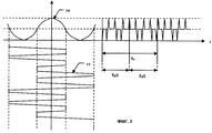
На фиг. 2 показано напряжение треугольной формы, подаваемое на фазовый модулятор кольцевого интерферометра гироскопа и импульсная последовательность разности фаз лучей. In FIG. Figure 2 shows the voltage of a triangular shape applied to the phase modulator of the ring gyroscope interferometer and the pulse sequence of the phase difference of the rays.
На фиг.3 показан вид выходного сигнала гироскопа в отсутствии вращения. Figure 3 shows a view of the output signal of the gyroscope in the absence of rotation.
На фиг.4 показан принцип формирования сигнала вращения на фотоприемнике кольцевого интерферометра гироскопа. Figure 4 shows the principle of the formation of the rotation signal on the photodetector of the annular gyroscope interferometer.
На фиг. 5 показан вид импульсной последовательности разности фаз лучей при осуществлении компенсации разности фаз Саньяка управляемым сдвигом фаз, формируемым с помощью изменения параметров сигнала, подаваемого на фазовый модулятор. In FIG. 5 is a view of a pulse sequence of the phase difference of the rays during the compensation of the Sagnac phase difference by a controlled phase shift generated by changing the parameters of the signal supplied to the phase modulator.
На фиг. 6 показан принцип формирования сигнала, вызванного изменением параметров напряжения треугольной формы, компенсирующего сигнал вращения гироскопа на выходе синхронного детектора. In FIG. Figure 6 shows the principle of signal generation caused by a change in the voltage parameters of a triangular shape, compensating for the gyroscope rotation signal at the output of a synchronous detector.
На фиг.7 показано изменение формы и частоты сигналов модуляции на периоде вспомогательной фазовой модуляции T0 1.7 shows a change in the shape and frequency of the modulation signals during the period of auxiliary phase modulation T 0 1 .
На фиг. 9 показан принцип формирования сигнала рассогласования, использующегося для подстройки амплитуды модулирующего напряжения треугольной формы. In FIG. Figure 9 shows the principle of generating a mismatch signal used to adjust the amplitude of a modulating voltage of a triangular shape.
На фиг.1 показана структурная схема волоконно-оптического гироскопа. Волоконно-оптический гироскоп состоит из кольцевого интерферометра и электронного блока обработки информации. В состав кольцевого интерферометра входит источник широкополосного оптического излучения 1, первый волоконный изотропный разветвитель 2, многофункциональная интегрально-оптическая схема 3, включающая в свой состав Y-делитель оптической мощности лучей и два фазовых модулятора. В состав интерферометра также входит волоконная чувствительная катушка 4 и фотоприемник 5 с предварительным усилителем 6. В качестве источника оптического излучения может быть использован полупроводниковый суперлюминесцентный диод или суперфлюоресцентный волоконный источник оптического излучения на основе одномодовых световодов с активированной редкоземельными элементами световедущей жилой [G. A. Sanders еt all. Fiber optic gyros for space, marine and aviation applications. SPIE, v.2837, p.61-71, 1996] . Первый волоконный разветвитель выполняется по стандартной тянуто-сплавной технологии, заключающейся в сварке двух отрезков одномодовых изотропных световодов с последующим формированием в месте сварки биконической перетяжки. Канальные волноводы Y-разветвителя многофункциональной интегрально-оптической схемы формируются в подложке ниобата лития по протон-обменной технологии, которая позволяет получить однополяризационные оптические волноводы. Два фазовых модулятора формируются на выходных плечах Y-делителя оптических лучей путем нанесения по обе стороны канальных волноводов трех металлических электродов, два из которых попарно между собой электрически соединены. Волоконная чувствительная катушка представляет собой многослойную многовитковую катушку, пропитанную специальным компаундом с длиной световода от 200 до 1000 м в зависимости от класса точности волоконно-оптического гироскопа. В качестве фотоприемника обычно используется стандартный p-i-n фотодиод. Figure 1 shows the structural diagram of a fiber optic gyroscope. Fiber optic gyroscope consists of a ring interferometer and an electronic information processing unit. The structure of the ring interferometer includes a source of broadband
Луч света от источника излучения поступает на один из входных концов первого волоконного разветвителя, делится им на два луча, один из которых поступает на вход Y-делителя многофункциональной интегрально-оптической схемы и делится им на два луча одинаковой интенсивности Эти два луча проходят затем во взаимно противоположных направлениях фазовые модуляторы и световод чувствительной катушки гироскопа, после чего они объединяются Y-делителем и, пройдя первый волоконный разветвитель, часть мощности объединенных лучей попадает на фотоприемник. Таким образом, на фотоприемнике наблюдается интерференция двух оптических лучей, прошедших световод чувствительной катушки в двух взаимно противоположных направлениях. A light beam from a radiation source enters one of the input ends of the first fiber splitter, divides it into two beams, one of which enters the input of the Y-divider of the multifunctional integrated optical circuit and divides it into two beams of the same intensity. These two beams then pass opposite directions, phase modulators and a fiber of the sensitive coil of the gyroscope, after which they are combined by a Y-divider and, having passed the first fiber splitter, part of the power of the combined beams falls on the photodetector nick. Thus, at the photodetector, interference is observed between two optical beams that have passed through the fiber of the sensing coil in two mutually opposite directions.
Электронный блок обработки информации содержит генератор напряжения треугольной формы 7, синхронный усилитель 8, выделяющий сигнал вращения гироскопа, блок управления параметрами напряжения треугольной формы 9, второй синхронный детектор 10 для выделения сигнала рассогласования и блок управления 11 для контроля амплитуды напряжения. The electronic information processing unit contains a voltage generator of a triangular shape 7, a synchronous amplifier 8 that extracts a gyroscope rotation signal, a voltage parameter control unit of a triangular shape 9, a second synchronous detector 10 to extract a mismatch signal and a control unit 11 to control the voltage amplitude.
На фиг. 2 показан вид напряжения треугольной формы 12, вырабатываемого генератором. Напряжение имеет период T0 при отсутствии вращения гироскопа. Первый полупериод T0/2 содержит, например, два треугольных импульса, которые имеют более высокую скорость нарастания по переднему фронту. Во второй полупериод T0/2 последовательность импульсов зеркально отображается. При подаче этого напряжения на электроды фазового модулятора между лучами кольцевого интерферометра формируется импульсная последовательность 13 разности фаз. В первую половину периода T0 формируется чередующаяся последовательность импульсов разности фаз с амплитудами -(π+Δ) радиан и (π-Δ) радиан, а во вторую половину периода T0 - чередующаяся последовательность импульсов, с амплитудами (π+Δ) радиан и -(π-Δ) радиан. Амплитуда вспомогательной фазовой модуляции определяется параметром Δ, который определяется следующим выражением:
![]()
где Uп - амплитуда напряжения треугольных импульсов,
η - эффективность интегрально-оптических фазовых модуляторов,
τ - время пробега световых лучей по световоду чувствительной катушки,
T1 - время нарастания переднего фронта треугольного напряжения,
T2 - время нарастания заднего фронта треугольного напряжения.In FIG. 2 shows a voltage view of a
![]()
where U p - the amplitude of the voltage of the triangular pulses,
η is the efficiency of integrated optical phase modulators,
τ is the travel time of light rays along the fiber of the sensitive coil,
T 1 - rise time of the leading edge of the triangular voltage,
T 2 - rise time of the trailing edge of the triangular voltage.
Здесь необходимо отметить, что из-за смены знака скорости нарастания напряжения в окрестности вершин импульсы разности фаз лучей кольцевого интерферометра имеют время нарастания и спада, равное τ.. It should be noted here that due to a change in the sign of the voltage rise rate in the vicinity of the vertices, the pulses of the phase difference of the rays of the ring interferometer have a rise and fall time equal to τ ..
На фиг.3 показан вид сигнала на фотоприемнике при рассмотренной выше фазовой модуляции лучей. Интенсивность на фотоприемнике зависит по закону косинуса 14 от разности фаз лучей, в силу чего сигнал на фотоприемнике имеет вид 15. Сигнал на фотоприемнике имеет характерные выбросы, которые обусловлены сменой знака скорости нарастания напряжения при переходе вершин треугольного напряжения вспомогательной фазовой модуляции. При усреднении по периоду фазовой модуляции T0 эти пикообразные импульсы, длительность которых кратна времени τ, по-видимому, не должны давать паразитного сигнала вращения гироскопа и для простоты рассмотрения в дальнейшем будем пренебрегать конечным временем нарастания и спада импульсов вспомогательной фазовой модуляции.Figure 3 shows a view of the signal at the photodetector with the above phase modulation of the rays. The intensity at the photodetector according to the law of
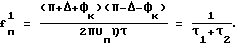
На фиг. 4 показан принцип формирования сигнала вращения 16 волоконно-оптического гироскопа. Пунктирной линией показано фазовое смещение, обусловленное эффектом Саньяка при вращении кольцевого интерферометра. Как видно из чертежа, частота сигнала, несущего информацию о вращении волоконно-оптического гироскопа, может быть выражена следующим образом:
fc=1/2nT0,
где n - количество пилообразных импульсов напряжения на полупериоде T0.In FIG. 4 shows the principle of generating a
f c = 1 / 2nT 0 ,
where n is the number of sawtooth voltage pulses at the half-cycle T 0 .
На фиг. 5 показан принцип формирования разности фаз лучей, позволяющих компенсировать разность фаз Саньяка. При положительных значениях угловой скорости, то есть при положительных значениях разности фаз Саньяка, треугольные импульсы имеют более высокую скорость нарастания переднего фронта и, наоборот, более низкую скорость нарастания заднего фронта по сравнению с импульсами напряжения, формируемыми в первую половину периода T0 при отсутствии вращения. Эти измененные импульсы формируются в течение отрезка времени T01 1. В течение отрезка времени T02 1 также увеличивается скорость нарастания напряжения зеркально отображенных треугольных импульсов по переднему фронту и уменьшается по модулю скорость спада напряжения по заднему фронту импульсов. В результате этой процедуры изменяется период следования треугольных импульсов напряжения, с помощью которых в этом случае осуществляется не только вспомогательная фазовая модуляция, но и осуществляется компенсация разности фаз Саньяка в кольцевом интерферометре. В первую часть T01 1 периода T0 импульсы разности фаз лучей кольцевого интерферометра имеют вид 19, а в оставшуюся часть T02 1 периода T0 1 импульсы разности фаз имеют вид 20.In FIG. 5 shows the principle of the formation of the phase difference of the rays, allowing to compensate for the phase difference of the Sagnac. For positive values of the angular velocity, that is, for positive values of the Sagnac phase difference, triangular pulses have a higher rise rate of the leading edge and, conversely, a lower rate of rise of the trailing edge compared to voltage pulses formed in the first half of the period T 0 in the absence of rotation . These altered pulses are generated during the time interval T 01 1 . During the time interval T 02 1 , the voltage rise rate of the mirrored triangular impulses along the rising edge also increases and the rate of voltage decrease along the falling edge of the pulses decreases modulo. As a result of this procedure, the repetition period of the triangular voltage pulses changes, with which in this case not only auxiliary phase modulation is performed, but also the Sagnac phase difference in the ring interferometer is compensated. In the first part T 01 1 of the period T 0, the phase difference pulses of the rays of the ring interferometer have the
На фиг. 6 показан принцип формирования переменного сигнала 21, компенсирующего сигнал вращения. Переменный сигнал, компенсирующий сигнал вращения гироскопа, обусловленный фазовым смещением Саньяка, формируется с помощью изменения скорости нарастания переднего фронта треугольных импульсов и скорости спада их заднего фронта описанным выше способом. Изменение скорости нарастания и спада фронтов треугольных импульсов напряжения осуществляется с помощью блока управления, который изменяет частоту следования импульсов в первую часть T01 1 и во вторую часть T02 1 периода T0 1. Для компенсации разности фаз Саньяка частота пилообразных импульсов напряжения в течение периода T01 1 уменьшается, а в течение T02 1 увеличивается или, наоборот, в зависимости от знака угловой скорости вращения. Изменение частоты следования треугольных импульсов напряжения блоком управления прекращается при отсутствии сигнала вращения на выходе синхронного усилителя.In FIG. 6 shows the principle of generating an alternating
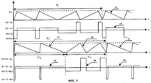
На фиг.7 показано изменение формы и частоты напряжения при осуществлении компенсации разности фаз Саньяка. Рассмотрим случай отрицательной скорости вращения, то есть компенсацию отрицательной разности фаз Саньяка. Figure 7 shows the change in the shape and frequency of the voltage during the compensation of the phase difference Sagnac. Consider the case of negative rotation speed, that is, compensation for the negative Sagnac phase difference.
В течение первого отрезка времени τ1 увеличения скорости нарастания напряжения, для величины τ1 можно записать:
![]()
Для величины отрезка времени T02 1 справедливо следующее соотношение:
![]()
Частота треугольных импульсов при этом равна:
Для величины τ3 (фиг.7) имеем следующее соотношение:
![]()
Для величины τ4 справедливо следующее соотношение:
![]()
Частота напряжения треугольной формы в этом случае:
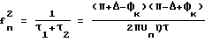
Разность частот треугольных импульсов напряжения, подаваемых на интегрально-оптический фазовый модулятор в режиме компенсации разности фаз Саньяка будет равна величине:
![]()
В данном случае φк = -φs и для скорости вращения гироскопа можно записать
![]()
где R - радиус намотки чувствительной катушки гироскопа,
λ - длина волны излучения источника,
n0 - показатель преломления материала световода,
Ω(t) - угловая скорость вращения.During the first time interval τ 1 increase in the rate of rise of voltage, for the value of τ 1 you can write:
![]()
For the value of the time interval T 02 1 the following relation is true:
![]()
The frequency of the triangular pulses in this case is equal to:
For the value of τ 3 (Fig.7) we have the following relationship:
![]()
For τ 4 the following relation is true:
![]()
The voltage frequency of the triangular shape in this case:
The frequency difference of the triangular voltage pulses supplied to the integrated optical phase modulator in the Sagnac phase difference compensation mode will be equal to:
![]()
In this case, φ к = -φ s and for the gyroscope rotation speed we can write
![]()
where R is the radius of the winding of the sensitive coil of the gyroscope,
λ is the radiation wavelength of the source,
n 0 is the refractive index of the material of the fiber,
Ω (t) is the angular velocity of rotation.
Измеряя разность частот следования треугольных импульсов в режиме компенсации разности фаз Саньяка, мы, тем самым, измеряем угловую скорость вращения с масштабным коэффициентом, который, в данном случае, выражается следующим образом:
![]()
Наибольший вклад в нестабильность масштабного коэффициента будет давать нестабильность эффективности η интегрально-оптических фазовых модуляторов, так как электрооптические коэффициенты ниобата лития зависят от изменения температуры окружающей среды; при изменении эффективности фазовых модуляторов изменяется величина Δ. Для стабилизации величины Δ/Uпη в электронном блоке обработки информации предусматривается вторая петля обратной связи.By measuring the difference in the repetition frequencies of triangular pulses in the Sagnac phase difference compensation mode, we thereby measure the angular velocity of rotation with a scale factor, which, in this case, is expressed as follows:
![]()
The largest contribution to the instability of the scale factor will come from the instability of the efficiency η of integrated optical phase modulators, since the electro-optical coefficients of lithium niobate depend on changes in the ambient temperature; when the efficiency of the phase modulators changes, the Δ value changes. To stabilize the value of Δ / U p η in the electronic information processing unit provides a second feedback loop.
На фиг.8 показан вид модулирующего напряжения 22 и закон изменения разности фаз 23 лучей кольцевого интерферометра. При изменении эффективности фазовых модуляторов модулирующее напряжение приобретает вид 24, а закон изменения разности фаз лучей - вид 25, в результате чего на фотоприемнике (фиг. 9) появляется импульсная последовательность напряжения 26. Величина Δ, определяющая амплитуду вспомогательной фазовой модуляции в кольцевом интерферометре, определяет и соотношение времен T1 и T2 на периоде T0 модулирующего напряжения, которые определяют длительность переднего и заднего фронтов напряжения треугольной формы. Соотношение времен в зависимости от Δ дается выражением:
![]()
Например, при Δ = π/2, T2=3T1, и в этом случае амплитуда импульсов разности фаз лучей составляет -3π/2 радиан и π/2 радиан. Таким образом, во время коррекции масштабного коэффициента волоконно-оптического гироскопа период следования T0 треугольного напряжения делится на две части в соотношении 1: 3, в первую часть которого происходит нарастание напряжения, а во вторую часть - линейный спад напряжения, и при этом амплитуда треугольного напряжения устанавливается таким образом, чтобы выполнялось условие:
![]()
При изменении эффективности фазового модулятора η или при изменении амплитуды треугольного напряжения, как отмечалось выше, на фотоприемнике появляется импульсная последовательность напряжения (сигнал рассогласования), свидетельствующая о нарушении условия соответствия амплитуд импульсов разности фаз лучей кольцевого интерферометра ±(π-Δ) радиан и ±(π+Δ) радиан. Амплитуду импульсов сигнала рассогласования при наличии вращения гироскопа можно представить в виде, при Δ = π/2:
Aрасс~4γ0cosφs+5γ
где γ0 - изменение амплитуды (π-Δ) разности фаз лучей из-за изменения эффективности фазовых модуляторов.On Fig shows a view of the modulating
![]()
For example, when Δ = π / 2, T 2 = 3T 1 , in this case, the amplitude of the pulses of the phase difference of the rays is -3π / 2 radian and π / 2 radian. Thus, during the correction of the scale factor of the fiber-optic gyroscope, the period T 0 of the triangular voltage is divided into two parts in a ratio of 1: 3, in the first part of which the voltage increases, and in the second part - the linear voltage drop, and the amplitude of the triangular voltage is set so that the condition:
![]()
When the efficiency of the phase modulator η changes or when the amplitude of the triangular voltage changes, as noted above, a voltage pulse sequence (mismatch signal) appears on the photodetector, indicating that the conditions for the correspondence of the pulse amplitudes of the phase difference of the rays of the ring interferometer ± (π-Δ) radian and ± ( π + Δ) rad. The amplitude of the pulses of the error signal in the presence of rotation of the gyroscope can be represented in the form, at Δ = π / 2:
A diff ~ 4γ 0 cosφ s +
where γ 0 is the change in the amplitude (π-Δ) of the phase difference of the rays due to changes in the efficiency of phase modulators.
Таким образом, в случае изменения величины Δ/Uпη, например, из-за изменения эффективности фазовых модуляторов, сигнал рассогласования на фотоприемнике присутствует всегда, при любой скорости вращения гироскопа, то есть коррекция масштабного коэффициента гироскопа может производиться в любой удобный момент времени.Thus, in the case of a change in Δ / U p η, for example, due to a change in the efficiency of phase modulators, the error signal at the photodetector is always present at any gyroscope rotation speed, i.e., the gyroscope scale factor can be corrected at any convenient time.
Сигнал рассогласования выделяется с помощью дополнительного синхронного детектора, работающего на частоте смены амплитуд импульсов разности фаз лучей кольцевого интерферометра, равной 1/(T1+T2). С помощью второго блока управления изменяется амплитуда напряжения, подаваемого на интегрально-оптические фазовые модуляторы до тех пор, пока на выходе синхронного детектора сигнал рассогласования не обратится в нуль. В результате этой процедуры стабилизируется величина Δ/Uпη, что приводит к стабилизации масштабного коэффициента волоконно-оптического гироскопа.The mismatch signal is extracted using an additional synchronous detector operating at a frequency of change in the pulse amplitudes of the phase difference of the rays of the ring interferometer equal to 1 / (T 1 + T 2 ). Using the second control unit, the amplitude of the voltage supplied to the integrated optical phase modulators is changed until the mismatch signal vanishes at the output of the synchronous detector. As a result of this procedure, the Δ / U p η value is stabilized, which leads to stabilization of the scale factor of the fiber-optic gyroscope.
Рассмотрим кольцевой интерферометр волоконно-оптического гироскопа со следующими параметрами: L= 200 м; R=0,025 м; λ=0,83 мкм; η=1рад/В; n=1,46. Для сигнала на выходе волоконно-оптического гироскопа можно записать:
![]()
Обычно в кольцевом интерферометре гироскопа используется фазовая модуляция с амплитудой ±π/2 радиан и ±3π/2, что достигается при Δ = π/2 радиан. Предположим теперь, что T1=2τ и соответственно T2=6τ, таким образом T0=8τ. Для амплитуды треугольного напряжения в этом случае имеем следующее соотношение:
![]()
Из этого соотношения следует, что Uпη = 3τ радиан и для выходного сигнала гироскопа справедливо соотношение:
Δf(t) = 4,82•102•Ω(t), град/с.
Максимальная разность частот при φs = π/2 радиан в данном случае составляет 166 кГц, что позволяет измерять угловую скорость вращения в диапазоне ±340o/сек.Consider a ring interferometer fiber optic gyro with the following parameters: L = 200 m; R = 0.025 m; λ = 0.83 μm; η = 1rad / V; n = 1.46. For the signal at the output of the fiber optic gyroscope, you can record:
![]()
Typically, a gyroscope ring interferometer uses phase modulation with an amplitude of ± π / 2 radians and ± 3π / 2, which is achieved with Δ = π / 2 radians. Suppose now that T 1 = 2τ and, accordingly, T 2 = 6τ, thus T 0 = 8τ. For the amplitude of the triangular voltage in this case, we have the following relation:
![]()
From this relation it follows that U p η = 3τ radian and for the output signal of the gyroscope the relation is true:
Δf (t) = 4.82 • 10 2 • Ω (t), deg / s.
The maximum frequency difference at φ s = π / 2 radians in this case is 166 kHz, which allows you to measure the angular velocity in the range of ± 340 o / sec.
При выборе Δ = π/4 и T1=2τ, Uпη = 2,5π радиан и диапазон измерения угловой скорости при этом расширяется до значения ±620o/сек.When choosing Δ = π / 4 and T 1 = 2τ, U p η = 2.5π radians and the range of measurement of angular velocity in this case expands to a value of ± 620 o / sec.
В заключение отметим, что треугольное напряжение может представлять из себя как непрерывно линейно нарастающее или убывающее напряжение, так и напряжение, представляющее собой ступенчатое нарастающее и убывающее напряжение. При этом длительность каждой ступеньки равна времени пробега лучей по световоду чувствительной катушки гироскопа, хотя использование такого напряжения в реальных устройствах весьма ограничено из-за большой дискретности отсчета изменения угловой скорости. In conclusion, we note that the triangular voltage can be a continuously linearly increasing or decreasing voltage, or voltage, which is a stepwise increasing and decreasing voltage. Moreover, the duration of each step is equal to the travel time of the rays along the fiber of the sensitive coil of the gyroscope, although the use of such voltage in real devices is very limited due to the large discreteness of the readout of the change in angular velocity.
Claims (1)
Priority Applications (1)
| Application Number | Priority Date | Filing Date | Title |
|---|---|---|---|
| RU2001121828A RU2194246C1 (en) | 2001-08-07 | 2001-08-07 | Method for processing optical fiber gyroscope ring interferometer signal |
Applications Claiming Priority (1)
| Application Number | Priority Date | Filing Date | Title |
|---|---|---|---|
| RU2001121828A RU2194246C1 (en) | 2001-08-07 | 2001-08-07 | Method for processing optical fiber gyroscope ring interferometer signal |
Publications (1)
| Publication Number | Publication Date |
|---|---|
| RU2194246C1 true RU2194246C1 (en) | 2002-12-10 |
Family
ID=20252373
Family Applications (1)
| Application Number | Title | Priority Date | Filing Date |
|---|---|---|---|
| RU2001121828A RU2194246C1 (en) | 2001-08-07 | 2001-08-07 | Method for processing optical fiber gyroscope ring interferometer signal |
Country Status (1)
| Country | Link |
|---|---|
| RU (1) | RU2194246C1 (en) |
Cited By (2)
| Publication number | Priority date | Publication date | Assignee | Title |
|---|---|---|---|---|
| RU2486470C1 (en) * | 2012-01-27 | 2013-06-27 | Федеральное государственное унитарное предприятие "Центр эксплуатации объектов наземной космической инфраструктуры" | Optical circuit of ring interferometer for fibre-optic gyroscope |
| RU2566412C1 (en) * | 2014-06-30 | 2015-10-27 | Федеральное государственное унитарное предприятие "Центр эксплуатации объектов наземной космической инфраструктуры" | Method to increase accuracy of fibre-optic gyroscope due to suppression of parasitic effects in integral-optical phase modulators |
-
2001
- 2001-08-07 RU RU2001121828A patent/RU2194246C1/en active IP Right Revival
Cited By (2)
| Publication number | Priority date | Publication date | Assignee | Title |
|---|---|---|---|---|
| RU2486470C1 (en) * | 2012-01-27 | 2013-06-27 | Федеральное государственное унитарное предприятие "Центр эксплуатации объектов наземной космической инфраструктуры" | Optical circuit of ring interferometer for fibre-optic gyroscope |
| RU2566412C1 (en) * | 2014-06-30 | 2015-10-27 | Федеральное государственное унитарное предприятие "Центр эксплуатации объектов наземной космической инфраструктуры" | Method to increase accuracy of fibre-optic gyroscope due to suppression of parasitic effects in integral-optical phase modulators |
Similar Documents
| Publication | Publication Date | Title |
|---|---|---|
| US5926275A (en) | Vibration error reduction servo for a fiber optic gyroscope | |
| JP5362180B2 (en) | Asynchronous demodulation of fiber optic gyroscope | |
| JP4130730B2 (en) | Fiber optic gyroscope | |
| EP0393987A2 (en) | Ring resonator gyro | |
| EP1718929B1 (en) | System and method for reducing fiber optic gyroscope color noise | |
| US5923424A (en) | Fiber optic gyroscope vibration error compensator | |
| JP2002534670A (en) | Kerr Effect Compensation for Interferometric Fiber Optic Gyroscope | |
| US5018859A (en) | Fiber optic gyroscope balanced plural serrodyne modulators phase difference control | |
| RU2512599C1 (en) | Method of improving accuracy of closed-loop fibre-optic gyroscope | |
| EP0535164B1 (en) | Demodulation reference signal source | |
| RU2343417C1 (en) | Method of low-frequency phase modulation for stabilisation of scale factor of fibre gyroscope | |
| RU2194246C1 (en) | Method for processing optical fiber gyroscope ring interferometer signal | |
| RU2500989C2 (en) | Electronic unit for fibre-optic gyroscope | |
| RU2482450C1 (en) | Apparatus for testing electronic unit of fibre-optic gyroscope | |
| RU2566412C1 (en) | Method to increase accuracy of fibre-optic gyroscope due to suppression of parasitic effects in integral-optical phase modulators | |
| RU2160885C1 (en) | Method of stabilization of scale factor of fiber-optical gyroscope | |
| RU2194245C2 (en) | Method for carrying out optical fiber gyroscope ring interferometer beam phase modulation | |
| RU2246097C2 (en) | Method of phase modulation in ringular interferometer of fiber-optic gyro | |
| RU2441202C2 (en) | Method for eliminating dead zones in fibre-optic gyroscope | |
| RU2160886C1 (en) | Procedure of processing of information of fiber-optical gyroscope | |
| RU2523759C1 (en) | Angular velocity range extension for open-circuit fibre-optic gyro | |
| RU2627020C1 (en) | Method for improving accuracy of fiber-optic gyroscopes under vibration influence | |
| RU2512598C1 (en) | Method of reducing precision readiness time of fibre-optic gyroscope | |
| RU2620933C1 (en) | Fiber optic gyroscope with a large dynamic range of measurement of angular speeds | |
| RU2194247C1 (en) | Method of phase modulation in circular interferometer of fiber-optic gyroscope |
Legal Events
| Date | Code | Title | Description |
|---|---|---|---|
| MM4A | The patent is invalid due to non-payment of fees |
Effective date: 20160808 |
|
| NF4A | Reinstatement of patent |
Effective date: 20190222 |