RU2192077C2 - Dual-band spiral antenna - Google Patents
Dual-band spiral antenna Download PDFInfo
- Publication number
- RU2192077C2 RU2192077C2 RU99122595/09A RU99122595A RU2192077C2 RU 2192077 C2 RU2192077 C2 RU 2192077C2 RU 99122595/09 A RU99122595/09 A RU 99122595/09A RU 99122595 A RU99122595 A RU 99122595A RU 2192077 C2 RU2192077 C2 RU 2192077C2
- Authority
- RU
- Russia
- Prior art keywords
- antenna
- emitters
- radiating
- segments
- section
- Prior art date
Links
Images


Classifications
-
- H—ELECTRICITY
- H01—ELECTRIC ELEMENTS
- H01Q—ANTENNAS, i.e. RADIO AERIALS
- H01Q21/00—Antenna arrays or systems
- H01Q21/28—Combinations of substantially independent non-interacting antenna units or systems
-
- H—ELECTRICITY
- H01—ELECTRIC ELEMENTS
- H01Q—ANTENNAS, i.e. RADIO AERIALS
- H01Q1/00—Details of, or arrangements associated with, antennas
- H01Q1/36—Structural form of radiating elements, e.g. cone, spiral, umbrella; Particular materials used therewith
- H01Q1/362—Structural form of radiating elements, e.g. cone, spiral, umbrella; Particular materials used therewith for broadside radiating helical antennas
-
- H—ELECTRICITY
- H01—ELECTRIC ELEMENTS
- H01Q—ANTENNAS, i.e. RADIO AERIALS
- H01Q11/00—Electrically-long antennas having dimensions more than twice the shortest operating wavelength and consisting of conductive active radiating elements
- H01Q11/02—Non-resonant antennas, e.g. travelling-wave antenna
- H01Q11/08—Helical antennas
-
- H—ELECTRICITY
- H01—ELECTRIC ELEMENTS
- H01Q—ANTENNAS, i.e. RADIO AERIALS
- H01Q5/00—Arrangements for simultaneous operation of antennas on two or more different wavebands, e.g. dual-band or multi-band arrangements
- H01Q5/30—Arrangements for providing operation on different wavebands
- H01Q5/378—Combination of fed elements with parasitic elements
-
- H—ELECTRICITY
- H01—ELECTRIC ELEMENTS
- H01Q—ANTENNAS, i.e. RADIO AERIALS
- H01Q5/00—Arrangements for simultaneous operation of antennas on two or more different wavebands, e.g. dual-band or multi-band arrangements
- H01Q5/40—Imbricated or interleaved structures; Combined or electromagnetically coupled arrangements, e.g. comprising two or more non-connected fed radiating elements
Landscapes
- Physics & Mathematics (AREA)
- Electromagnetism (AREA)
- Details Of Aerials (AREA)
- Variable-Direction Aerials And Aerial Arrays (AREA)
- Support Of Aerials (AREA)
Abstract
Description
Предшествующий уровень техники
I. Область техники
Настоящее изобретение относится к антеннам. Более конкретно, настоящее изобретение относится к новой и улучшенной двухдиапазонной спиральной антенне, имеющей связанные (электромагнитно) излучательные сегменты.State of the art
I. Technical Field
The present invention relates to antennas. More specifically, the present invention relates to a new and improved dual-band helical antenna having coupled (electromagnetic) radiating segments.
II. Уровень техники
Современные устройства персональной связи находят успешное и широко распространяемое использование в многочисленных мобильных и портативных приложениях. Для традиционных мобильных применений желание минимизировать размер устройства связи, такого как, например, мобильный телефон, привело к небольшому снижению габаритов и массы устройства. Однако поскольку популярность портативных и ручных применений увеличивается, то резко возросла потребность в устройствах все меньших по размеру. Последние разработки в области технологии изготовления процессоров, технологии изготовления аккумуляторов и технологии изготовления средств связи позволили за последние несколько лет очень существенно снизить размер и вес портативных устройств.II. State of the art
Modern personal communication devices find successful and widespread use in numerous mobile and portable applications. For traditional mobile applications, the desire to minimize the size of a communication device, such as, for example, a mobile phone, has led to a slight reduction in the size and weight of the device. However, as the popularity of portable and handheld applications is increasing, the demand for smaller devices has increased dramatically. Recent developments in the field of processor manufacturing technology, battery manufacturing technology and communication technology manufacturing technology have allowed the size and weight of portable devices to be significantly reduced over the past few years.
Антенные устройства - это та область, в которой требуется снижение размеров. Размер и вес антенны играет важную роль в снижении габаритов и массы устройств связи. Полный размер антенны может влиять на размер корпуса устройства. Антенны с меньшим диаметром и более короткой длиной могут обеспечить меньшие размеры устройства в целом, а также и меньшие размеры корпуса. Antenna devices are the area where size reduction is required. The size and weight of the antenna plays an important role in reducing the size and weight of communication devices. The full size of the antenna may affect the size of the device. Antennas with a smaller diameter and shorter length can provide smaller dimensions of the device as a whole, as well as smaller housing sizes.
Размер устройства - это не единственный фактор, который должен учитываться при конструировании антенн для портативных применений. Другим фактором, который должен учитываться при конструировании антенн, является ослабление и/или эффекты затенения, возникающие из-за близости к антенне пользователя при нормальных режимах работы. Кроме того, еще одним фактором являются параметры линии связи, такие как, например, диаграммы направленности антенны и рабочие частоты. Device size is not the only factor to consider when designing antennas for portable applications. Another factor that should be considered when designing antennas is the attenuation and / or shading effects that occur due to proximity to the user's antenna under normal operating conditions. In addition, parameters of the communication line, such as, for example, antenna patterns and operating frequencies, are another factor.
Антенна, которая находит широкое использование в спутниковых системах связи, - это спиральная антенна. Одной из причин популярности спиральной антенны в спутниковых системах является ее способность создавать и принимать излучение с круговой поляризацией, используемое в таких системах. Кроме того, поскольку спиральная антенна способна создавать диаграмму направленности, которая близка к полусферической, спиральная антенна особенно хорошо подходит для использования в спутниковых системах мобильной связи и в навигационных спутниковых системах. An antenna that is widely used in satellite communications systems is a spiral antenna. One of the reasons for the popularity of the spiral antenna in satellite systems is its ability to create and receive circularly polarized radiation used in such systems. In addition, since the helical antenna is capable of creating a directivity pattern that is close to hemispherical, the helical antenna is particularly well suited for use in satellite mobile communication systems and navigation satellite systems.
Традиционные спиральные антенны изготавливаются путем скручивания излучателей антенны в спиральную структуру. Обычная спиральная антенна - это четырехзаходная (четырехэлементная) спиральная антенна, в которой используются четыре излучателя, пространственно разнесенные равномерно вокруг сердечника и возбуждаемые в фазовой квадратуре (т.е. излучатели возбуждаются сигналами, которые отличаются по фазе на одну четверть периода или 90o). Длина излучателей обычно кратна целому числу четверти длины волны рабочей частоты устройства связи. Диаграммы направленности антенны обычно настраиваются путем изменения шага излучателя, длины излучателя (кратна целому числу четверти длины волны) и диаметру сердечника.Traditional spiral antennas are made by twisting the antenna emitters into a spiral structure. A conventional helical antenna is a four-way (four-element) helical antenna that uses four emitters, spatially spaced evenly around the core and excited in phase quadrature (i.e., emitters are excited by signals that differ in phase by one quarter of a period or 90 ° ). The length of the emitters is usually a multiple of an integer quarter of the wavelength of the operating frequency of the communication device. The antenna patterns are usually tuned by changing the pitch of the emitter, the length of the emitter (a multiple of an integer of a quarter of the wavelength) and the diameter of the core.
Обычная спиральная антенна может быть изготовлена с использованием проволочной или полосковой технологии. При полосковой технологии излучатели антенны протравливаются или наносятся на тонкую гибкую основу. Излучатели располагаются так, чтобы они были параллельны друг другу, но были под тупым углом к сторонам (или краям) основы. Затем основа формируется или скатывается в цилиндрическую, коническую или другую соответствующую форму, в результате чего полосковые излучатели приобретают форму спирали. A conventional helical antenna can be made using wire or strip technology. In strip technology, antenna emitters are etched or applied onto a thin, flexible substrate. The emitters are arranged so that they are parallel to each other, but are at an obtuse angle to the sides (or edges) of the base. Then the base is formed or rolled into a cylindrical, conical or other appropriate shape, as a result of which the strip emitters take the form of a spiral.
Однако эта традиционная спиральная антенна также имеет длину излучателей, равную кратному целому четверти длины волны резонансной частоты; в результате полная длина антенны больше, чем длина, необходимая для некоторых портативных или мобильных применений. However, this traditional helical antenna also has emitters equal to a multiple of a quarter of the resonant frequency wavelength; as a result, the total antenna length is longer than the length required for some portable or mobile applications.
Кроме того, в применениях, где передача и прием сигналов связи осуществляется на разных частотах, требуются двухдиапазонные антенны. Однако часто имеющиеся двухдиапазонные антенны не обладают требуемой конфигурацией. Например, один из способов изготовления двухдиапазонной антенны состоит в том, что две однодиапазонные четырехзаходные спиральные антенны составляются ярусно торец к торцу так, что они образуют единый цилиндр. Однако недостаток такого решения заключается в том, что антенна длиннее, чем та, которая могла бы потребоваться для портативных или переносных устройств. In addition, in applications where the transmission and reception of communication signals is carried out at different frequencies, dual-band antennas are required. However, the often available dual-band antennas do not have the required configuration. For example, one of the methods of manufacturing a dual-band antenna is that two single-band, four-way helical antennas are tiered end-to-end so that they form a single cylinder. However, the disadvantage of this solution is that the antenna is longer than that which might be required for portable or portable devices.
В соответствии с другой технологией обеспечения работы на двух диапазонах использовались две отдельные однодиапазонные антенны. Однако для переносных устройств такие две антенны должны быть расположены в непосредственной близости друг от друга. Две однодиапазонные антенны, расположенные вблизи друг от друга на портативных или переносных устройствах, будут приводить к взаимодействию между этими двумя антеннами, приводя к ухудшению рабочих параметров и к нежелательным помехам. In accordance with another dual-band technology, two separate single-band antennas were used. However, for portable devices, such two antennas must be located in close proximity to each other. Two single-band antennas located close to each other on portable or portable devices will result in interaction between the two antennas, resulting in poor performance and unwanted interference.
Раскрытие изобретения
Настоящее изобретение реализуется в новой улучшенной двухдиапазонной спиральной антенне, имеющей две группы из одного или нескольких спирально скрученных излучателей. Излучатели скручены или накручены так, что антенна имеет цилиндрическую, коническую или другую соответствующую форму для того, чтобы оптимизировать или, по-другому, получить требующиеся диаграммы направленности антенны. Согласно изобретению одна группа излучателей предназначена для работы на первой частоте, а вторая группа излучателей выполнена для работы на второй частоте, которая предпочтительно отличается от первой частоты. Каждая группа излучателей имеет соответствующую схему возбуждения для получения сигналов, возбуждающих излучатели. Таким образом, двухдиапазонная антенна может быть описана как состоящая из двух однодиапазонных антенн, причем каждая однодиапазонная антенна имеет излучательную часть и возбуждающую часть.Disclosure of Invention
The present invention is implemented in a new improved dual-band helical antenna having two groups of one or more helically twisted emitters. The emitters are twisted or wound so that the antenna has a cylindrical, conical or other appropriate shape in order to optimize or, in another way, to obtain the desired radiation patterns of the antenna. According to the invention, one group of emitters is designed to operate at a first frequency, and the second group of emitters is designed to operate at a second frequency, which is preferably different from the first frequency. Each group of emitters has a corresponding excitation circuit for receiving signals exciting emitters. Thus, a dual-band antenna can be described as consisting of two single-band antennas, with each single-band antenna having a radiating part and an exciting part.
Для обеспечения двухдиапазонной работы в объединенном антенном блоке две группы излучателей и соответствующие им схемы возбуждения (т.е. две однодиапазонные антенны) составляются ярусно или располагаются торец к торцу так, что они оказываются соосно ориентированными по отношению друг к другу. To ensure dual-band operation in the combined antenna unit, two groups of emitters and their corresponding excitation schemes (i.e., two single-band antennas) are arranged in tiers or face-to-face so that they are coaxially oriented with respect to each other.
В одном из вариантов составленные антенны располагаются так, что они имеют одну и ту же ориентацию. То есть, их возбуждающие части ориентированы в направлении одного конца двухдиапазонной антенны, а их излучательные части ориентированы в направлении другого конца. Следовательно, части двухдиапазонной антенны, от одного конца антенны до другого, следующие: излучательная часть первой однодиапазонной антенны, возбуждающая часть первой однодиапазонной антенны, излучательная часть второй однодиапазонной антенны и возбуждающая часть второй однодиапазонной антенны. In one embodiment, the composed antennas are arranged so that they have the same orientation. That is, their exciting parts are oriented in the direction of one end of the dual-band antenna, and their radiating parts are oriented in the direction of the other end. Therefore, the parts of the dual-band antenna, from one end of the antenna to the other, are as follows: the radiative part of the first single-band antenna, the exciting part of the first single-band antenna, the radiative part of the second single-band antenna, and the exciting part of the second single-band antenna.
В одном из вариантов каждый излучатель из по меньшей мере одной группы излучателей состоит из двух излучательных сегментов. Один излучательный сегмент вытянут в виде спирали от первого конца излучательной части антенны в направлении другого конца излучательной части. Второй излучательный сегмент вытянут в виде спирали от центральной области двухдиапазонной антенны (т.е. от другого конца излучательной части второй однодиапазонной антенны) в направлении первого конца излучательной части. In one embodiment, each emitter from at least one group of emitters consists of two emitting segments. One radiating segment is elongated in a spiral form from the first end of the radiating part of the antenna in the direction of the other end of the radiating part. The second radiating segment is elongated in a spiral form from the central region of the dual-band antenna (i.e., from the other end of the radiating part of the second single-band antenna) in the direction of the first end of the radiating part.
В этом варианте каждый сегмент в группе физически отделен от соседнего сегмента (соседних сегментов) в этой группе, но электромагнитно с ним связан. Длина сегментов в группе выбирается так, чтобы группа (т.е. излучатель(и)) резонировала на конкретной частоте. Поскольку сегменты в группе физически отделены друг от друга, но электромагнитно связаны друг с другом, длина, на которой излучатель резонирует, для заданной частоты может быть выполнена более короткой, чем длина излучателя обычной спиральной антенны. In this embodiment, each segment in the group is physically separated from the neighboring segment (s) in this group, but is electromagnetically coupled to it. The length of the segments in the group is selected so that the group (i.e., the emitter (s)) resonates at a particular frequency. Since the segments in the group are physically separated from each other, but are electromagnetically connected to each other, the length at which the emitter resonates for a given frequency can be made shorter than the length of the emitter of a conventional spiral antenna.
Вследствие такой структуры электромагнитная энергия из первого сегмента излучателя в первой группе связана со вторым сегментом этого излучателя. Эффективная электрическая длина этих объединенных сегментов вызывает резонанс излучателя в первой группе, состоящей из одного или более излучателей, на заданной частоте. Due to this structure, electromagnetic energy from the first segment of the emitter in the first group is associated with the second segment of this emitter. The effective electrical length of these combined segments causes resonance of the emitter in the first group of one or more emitters at a given frequency.
Достоинство этого варианта с несколькими связанными сегментами состоит в том, что антенна легко может быть настроена на заданную частоту путем регулировки или подгонки длины излучательных сегментов. Поскольку излучатели не являются одной непрерывной линией, а выполняются в виде набора из двух или более сегментов, длина сегментов легко изменяется после того, как антенна изготовлена, чтобы должным образом настраиваться на частоту антенны. Кроме того, полная диаграмма направленности антенны, по существу, не изменяется при настройке, поскольку сегменты могут быть подогнаны без изменения места их расположения. The advantage of this variant with several connected segments is that the antenna can easily be tuned to a given frequency by adjusting or adjusting the length of the radiating segments. Since the emitters are not a single continuous line, but are made in the form of a set of two or more segments, the length of the segments easily changes after the antenna is made to properly tune to the antenna frequency. In addition, the full antenna pattern does not essentially change during tuning, since the segments can be adjusted without changing their location.
В другом варианте элементы двухдиапазонной антенны располагаются на основе так, что заземленный слой для возбуждающей части первой однодиапазонной антенны используется как короткозамыкающее кольцо вокруг конца излучателей второй однодиапазонной антенны. Вследствие такой конфигурации нет необходимости в какой-либо дополнительной структуре для обеспечения функции короткого замыкания, что позволяет антенне резонировать при длине, равной половине длины волны резонансной частоты, умноженной на четное целое число. In another embodiment, the elements of the dual-band antenna are arranged on the base such that the ground plane for the exciting part of the first single-band antenna is used as a short-circuit ring around the end of the emitters of the second single-band antenna. Due to this configuration, there is no need for any additional structure to provide a short circuit function, which allows the antenna to resonate at a length equal to half the wavelength of the resonant frequency multiplied by an even integer.
В еще одном варианте схема возбуждения, используемая для формирования фазовых сигналов для излучателей, модифицирована для экономии пространства (места). А конкретно, части схемы возбуждения размещены на излучательной части антенны, вследствие чего закрывается меньшая область возбуждающей части. В результате полный размер антенны может быть уменьшен и снижается величина потерь в линии подачи питания (возбуждающих сигналов). In yet another embodiment, the drive circuit used to generate phase signals for the emitters is modified to save space (space). Specifically, parts of the excitation circuit are located on the radiating part of the antenna, whereby a smaller area of the exciting part is closed. As a result, the overall size of the antenna can be reduced and the amount of loss in the power supply line (excitation signals) is reduced.
В еще одном варианте антенны предлагается контакт для подачи сигнала на первую однодиапазонную антенную секцию. Контакт вытянут от возбуждающей части первой однодиапазонной антенны. Когда антенне придается форма цилиндра или другая соответствующая форма, контакт совмещается с осью антенны. А конкретно, в предпочтительном варианте контакт вытянут радиально внутрь для формирования конструкции, в которой линия подвода питания расположена по центру антенны. Следовательно, контакт и линия питания не влияют на диаграмму направленности второй однодиапазонной антенны. In yet another embodiment of the antenna, a contact is provided for supplying a signal to a first single-band antenna section. The contact extends from the exciting part of the first single-band antenna. When a cylinder shape or other corresponding shape is given to the antenna, the contact is aligned with the axis of the antenna. Specifically, in a preferred embodiment, the contact is extended radially inward to form a structure in which a power supply line is located in the center of the antenna. Therefore, the contact and the power line do not affect the radiation pattern of the second single-band antenna.
Достоинство изобретения состоит в том, что диаграммы направленности антенны могут подстраиваться для получения максимального уровня сигнала (напряженности поля) в одном направлении вдоль оси антенны. Следовательно, для определенных приложений, таких как, например, спутниковые системы связи, диаграммы направленности антенны могут быть оптимизированы для получения максимального уровня сигнала в направлении вверх, наружу от земли. The advantage of the invention is that the antenna patterns can be adjusted to obtain the maximum signal level (field strength) in one direction along the axis of the antenna. Therefore, for certain applications, such as, for example, satellite communication systems, antenna patterns can be optimized to obtain the maximum signal level in the direction up, out of the earth.
Другое достоинство изобретения состоит в том, что ток, протекающий от излучателей второй антенны в контакт первой антенны, стремится расширить диаграмму направленности первой антенны. Эта тенденция сделать антенну более подходящей для определенных приложений спутниковой связи используется в системах связи, когда спутники вращаются на низкой околоземной орбите. Another advantage of the invention is that the current flowing from the emitters of the second antenna into the contact of the first antenna tends to expand the radiation pattern of the first antenna. This tendency to make the antenna more suitable for certain satellite communications applications is used in communications systems when satellites rotate in low Earth orbit.
Краткое описание чертежей
Особенности и достоинства настоящего изобретения станут более явными из нижеизложенного подробного описания варианта изобретения с учетом чертежей, на которых аналогичные элементы обозначены одними и теми же номерами позиций. Кроме того, слева стоящая цифра(ы) в номере позиции указывает на номер чертежа, на котором эта позиция появилась впервые.Brief Description of the Drawings
Features and advantages of the present invention will become more apparent from the following detailed description of an embodiment of the invention, taking into account the drawings, in which like elements are denoted by the same reference numerals. In addition, the left-standing digit (s) in the item number indicates the drawing number on which this item first appeared.
Фиг.1А - схема, иллюстрирующая обычную проволочную четырехзаходную спиральную антенну. 1A is a diagram illustrating a conventional four-wire helical antenna.
Фиг. 1В - схема, иллюстрирующая обычную полосковую четырехзаходную спиральную антенну. FIG. 1B is a diagram illustrating a conventional strip four-way helical antenna.
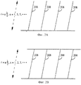
Фиг. 2А - схема, иллюстрирующая плоскостное отображение четырехзаходной спиральной антенны с разомкнутым контуром или с разомкнутыми выводами. FIG. 2A is a diagram illustrating a planar display of an open loop four-way helical antenna or with open leads.
Фиг. 2В - схема, иллюстрирующая плоскостное отображение четырехзаходной спиральной антенны с короткозамкнутым контуром. FIG. 2B is a diagram illustrating a planar view of a snapped four-way helical antenna.
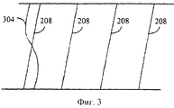
Фиг. 3 - схема, иллюстрирующая распределение тока по излучателю четырехзаходной спиральной антенны с короткозамкнутым контуром. FIG. 3 is a diagram illustrating a current distribution over an emitter of a squirrel-cage spiral antenna.
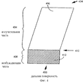
Фиг. 4 - схема, иллюстрирующая дальнюю поверхность протравленной основы полосковой спиральной антенны. FIG. 4 is a diagram illustrating a distal surface of an etched base of a strip helical antenna.
Фиг. 5 - схема, иллюстрирующая ближнюю поверхность протравленной основы полосковой спиральной антенны. FIG. 5 is a diagram illustrating a proximal surface of an etched base of a strip helical antenna.
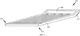
Фиг. 6 - схема, иллюстрирующая перспективу протравленной основы полосковой спиральной антенны. FIG. 6 is a diagram illustrating a perspective of an etched base of a strip helical antenna.
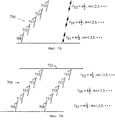
Фиг. 7А - схема, иллюстрирующая излучатель с несколькими связанными сегментами, с разомкнутым контуром, имеющий пять связанных сегментов, в соответствии с одним из вариантов изобретения. FIG. 7A is a diagram illustrating an open loop emitter with several connected segments having five connected segments, in accordance with one embodiment of the invention.
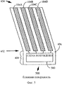
Фиг. 7В - схема, иллюстрирующая пару короткозамкнутых излучателей с несколькими связанными сегментами в соответствии с одним из вариантов изобретения. FIG. 7B is a diagram illustrating a pair of short-circuited emitters with several connected segments in accordance with one embodiment of the invention.
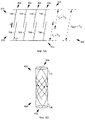
Фиг. 8А - схема, иллюстрирующая плоское отображение четырехзаходной спиральной антенны короткозамкнутой, с несколькими связанными сегментами в соответствии с одним из вариантов изобретения. FIG. 8A is a diagram illustrating a planar display of a four-way helical short-circuited antenna with several connected segments in accordance with one embodiment of the invention.
Фиг. 8В - схема, иллюстрирующая четырехзаходную спиральную антенну с несколькими связанными сегментами, в форме цилиндра в соответствии с одним из вариантов изобретения. FIG. 8B is a diagram illustrating a four-way helical antenna with several connected segments in the form of a cylinder in accordance with one embodiment of the invention.
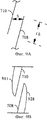
Фиг. 9А - схема, иллюстрирующая перекрытие δ сегментов излучателя и промежуток s между сегментами в соответствии с одним из вариантов изобретения. FIG. 9A is a diagram illustrating the overlapping δ of emitter segments and the gap s between segments in accordance with one embodiment of the invention.
Фиг. 9В - схема, иллюстрирующая пример распределения токов излучательных сегментов спиральной антенны с несколькими связанными сегментами. FIG. 9B is a diagram illustrating an example of a current distribution of radiating segments of a spiral antenna with several connected segments.
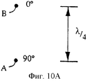
Фиг.10А - схема, иллюстрирующая два точечных источника, излучающих сигналы, отличающиеся по фазе на 90o.10A is a diagram illustrating two point sources emitting signals that are 90 o phase different.
Фиг. 10В - схема, иллюстрирующая диаграмму направленности по напряженности поля для точечных источников, проиллюстрированных на фиг.10А. FIG. 10B is a diagram illustrating a field strength radiation pattern for point sources illustrated in FIG. 10A.
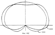
Фиг. 10С - схема, иллюстрирующая диаграмму направленности по напряженности поля с круговой поляризацией для обычной спиральной антенны и диаграмму направленности по напряженности поля с круговой поляризацией для спиральной антенны, имеющей контакт для подвода питания, совмещенный с осью антенны. FIG. 10C is a diagram illustrating a circularly polarized radiation pattern for a conventional helical antenna and a circularly polarized radiation pattern for a spiral antenna having a contact for supplying power aligned with the axis of the antenna.
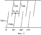
Фиг. 11 - схема, иллюстрирующая вариант, в котором каждый сегмент расположен на эквидистантном расстоянии от сегментов с любой стороны. FIG. 11 is a diagram illustrating an embodiment in which each segment is located at an equidistant distance from the segments on either side.
Фиг. 12 - схема, иллюстрирующая пример выполнения антенны с несколькими связанными сегментами согласно одному из вариантов изобретения. FIG. 12 is a diagram illustrating an example embodiment of an antenna with several connected segments according to one embodiment of the invention.
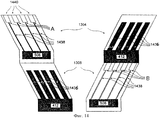
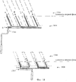
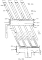
Фиг.13 - схема, иллюстрирующая плоскостные отображения поверхностей ярусно составленной двухдиапазонной спиральной антенны в соответствии с одним из вариантов изобретения. 13 is a diagram illustrating planar displays of surfaces of a tiered constituted dual-band helical antenna in accordance with one embodiment of the invention.
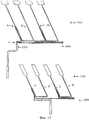
Фиг.14 - схема, иллюстрирующая плоскостные отображения поверхностей ярусно составленной двухдиапазонной спиральной антенны в соответствии с одним из вариантов изобретения, в котором точки возбуждения (подачи сигнала) для излучателей расположены на расстоянии от схемы возбуждения. Fig. 14 is a diagram illustrating planar displays of surfaces of a tiered-structured dual-band helical antenna in accordance with one embodiment of the invention, in which the excitation (signal) points for emitters are located at a distance from the excitation circuit.
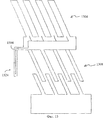
Фиг. 15 - схема, иллюстрирующая плоскостное отображение контакта, используемого для подачи питания (сигнала возбуждения) на антенну, представляющую собой ярусно составленную двухдиапазонную спиральную антенну, в соответствии с одним из вариантов изобретения. FIG. 15 is a diagram illustrating a planar display of a contact used to supply power (excitation signal) to an antenna, which is a tiered-structured dual-band helical antenna, in accordance with one embodiment of the invention.
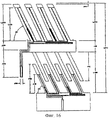
Фиг.16 - схема, иллюстрирующая примерные размеры для ярусно составленной двухдиапазонной спиральной антенны в соответствии с одним из вариантов изобретения. 16 is a diagram illustrating exemplary dimensions for a tiered constituted dual-band helical antenna in accordance with one embodiment of the invention.
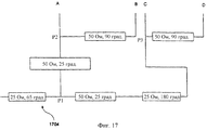
Фиг.17 - схема, иллюстрирующая пример обычной схемы возбуждения с квадратурными сигналами. 17 is a diagram illustrating an example of a conventional quadrature signal drive circuit.
Фиг.18 - схема, иллюстрирующая схему возбуждения, имеющая части, которые проходят в излучатели антенны, в соответствии с одним из вариантов изобретения. Fig. 18 is a diagram illustrating an excitation circuit having parts that extend into antenna emitters in accordance with one embodiment of the invention.
Фиг. 19 - схема, иллюстрирующая схемы возбуждения с сигнальными дорожками, включая пути подачи сигналов, для антенн согласно одному из вариантов изобретения. FIG. 19 is a diagram illustrating drive circuits with signal paths, including signal paths, for antennas according to one embodiment of the invention.
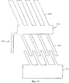
Фиг.20 - схема, иллюстрирующая конфигурацию для заземленного слоя антенны, согласно одному из вариантов изобретения. 20 is a diagram illustrating a configuration for an earthed layer of an antenna according to one embodiment of the invention.
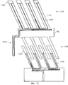
Фиг. 21 - схема, иллюстрирующая заземленные слои и сигнальные дорожки двухдиапазонной антенны, наложенные согласно одному из вариантов изобретения. FIG. 21 is a diagram illustrating grounded layers and signal paths of a dual-band antenna superimposed according to one embodiment of the invention.
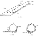
Фиг. 22А - схема, иллюстрирующая конструкцию для закрепления антенны в цилиндрической или другой соответствующей форме в соответствии с одним из вариантов изобретения. FIG. 22A is a diagram illustrating a structure for securing an antenna in a cylindrical or other appropriate shape in accordance with one embodiment of the invention.
Фиг.22В-22Е - схемы, иллюстрирующие формирование антенны в форме цилиндра или другой соответствующей форме в соответствии с вариантом, проиллюстрированном на фиг.22А. FIGS. 22B-22E are diagrams illustrating the formation of an antenna in the form of a cylinder or other appropriate shape in accordance with the embodiment illustrated in FIG. 22A.
Фиг.23А - схема, иллюстрирующая каркас, подходящий для использования при удерживании антенны в форме цилиндра или другой соответствующей форме, согласно одному из вариантов. Figa is a diagram illustrating a frame suitable for use when holding the antenna in the form of a cylinder or other appropriate shape, according to one of the options.
Фиг. 23В и 23С - схемы, иллюстрирующие формирование антенны в форме цилиндра или другой соответствующей форме в соответствии с вариантом, проиллюстрированном на фиг.23А. FIG. 23B and 23C are diagrams illustrating the formation of an antenna in the form of a cylinder or other appropriate shape in accordance with the embodiment illustrated in FIG. 23A.
Подробное описание предпочтительных вариантов осуществления изобретения
I. Обзор и обсуждение изобретения
Настоящее изобретение направлено на создание двухдиапазонной спиральной антенны, способной резонировать на двух различных рабочих частотах. Две спиральные антенны ярусно составлены торец к торцу, при этом одна антенна резонирует на первой частоте, а другая антенна резонирует на второй частоте. Каждая антенна имеет излучательную часть, содержащую один или несколько спирально скрученных излучателей. Каждая антенна также имеет возбуждающую часть, содержащую схему возбуждения и заземленный слой. Имеется контакт для подачи сигнала на первую однодиапазонную антенну. Контакт вытянут от возбуждающей части первой однодиапазонной антенны. Когда антенна сформирована в виде цилиндра или другой соответствующей формы, то контакт совмещается с осью антенны. А более конкретно, в предпочтительном варианте контакт вытянут в радиальном направлении внутрь антенны для того, чтобы получить запитывающую структуру, расположенную по центру. Ниже подробно описано, как это реализуется в соответствии с несколькими вариантами изобретения.DETAILED DESCRIPTION OF PREFERRED EMBODIMENTS
I. Overview and discussion of the invention
The present invention is directed to a dual-band helical antenna capable of resonating at two different operating frequencies. Two helical antennas are tiered composed end to end, with one antenna resonating at the first frequency, and the other antenna resonating at the second frequency. Each antenna has a radiating part containing one or more spirally twisted emitters. Each antenna also has an excitation part comprising an excitation circuit and a grounded layer. There is a contact for supplying a signal to the first single-band antenna. The contact extends from the exciting part of the first single-band antenna. When the antenna is formed in the form of a cylinder or other appropriate shape, then the contact is aligned with the axis of the antenna. More specifically, in a preferred embodiment, the contact is radially extended inwardly of the antenna in order to obtain a center-mounted feeding structure. Below is described in detail how this is implemented in accordance with several variants of the invention.
II. Примерные условия эксплуатации
В широком смысле изобретение может быть реализовано в любой системе, для которой может использоваться технология спиральных антенн. Одним из примеров таких условий эксплуатации (применений) является система связи, в которой пользователи, имеющие стационарно установленные, мобильные и/или портативные телефоны, связываются с партнерами по спутниковому каналу связи. При этих условиях эксплуатации требуется, чтобы телефон имел антенну, настроенную на частоту спутникового канала связи.II. Approximate operating conditions
In a broad sense, the invention can be implemented in any system for which helical antenna technology can be used. One example of such operating conditions (applications) is a communication system in which users who have fixed, mobile and / or portable telephones communicate with partners via a satellite communication channel. Under these operating conditions, the telephone must have an antenna tuned to the frequency of the satellite communication channel.
Настоящее изобретение раскрыто через терминологию этих условий эксплуатации. Описание представлено в этих терминах только для удобства. Предполагается, что изобретение не ограничивается применением только в этих условиях эксплуатации. Фактически, после прочтения нижеприведенного описания специалистам в данной области техники станет очевидным, как можно реализовать изобретение в других условиях эксплуатации. The present invention is disclosed through the terminology of these operating conditions. The description is presented in these terms for convenience only. It is assumed that the invention is not limited to use only in these operating conditions. In fact, after reading the description below, it will become apparent to those skilled in the art how the invention can be implemented in other operating conditions.
III. Обычная спиральная антенна
Перед подробным раскрытием вариантов выполнения изобретения полезно описать излучательную часть некоторых обычных спиральных антенн. А конкретно, в этом разделе документа описаны излучательные части некоторых традиционных четырехзаходных спиральных антенн. Фиг.1А и 1В - схемы, иллюстрирующие излучательную часть 100 обычной четырехзаходной спиральной антенны проволочного типа и полоскового типа соответственно. Излучательная часть 100, проиллюстрированная на фиг.1А и 1В, является частью четырехзаходной спирали антенны, это означает, что она имеет четыре излучателя 104, работающих в фазовой квадратуре. Как показано на фиг.1А и 1В, излучатели 104 закручены для получения круговой поляризации.III. Conventional Spiral Antenna
Before disclosing embodiments of the invention in detail, it is useful to describe the radiative portion of some conventional helical antennas. Specifically, this section of the document describes the radiative parts of some traditional four-way helical antennas. 1A and 1B are diagrams illustrating a radiating portion 100 of a conventional four-way helical antenna of wire type and strip type, respectively. The radiating part 100 illustrated in FIGS. 1A and 1B is part of a four-way antenna helix, which means that it has four
Фиг. 2А и 2В - это схемы, иллюстрирующие плоскостное отображение излучательной части обычных четырехзаходных спиральных антенн. Другими словами, фиг. 2А и 2В иллюстрируют излучатели, как они будут выглядеть, если цилиндр антенны развернуть на плоской поверхности. FIG. 2A and 2B are diagrams illustrating a planar display of the radiative portion of conventional four-way helical antennas. In other words, FIG. 2A and 2B illustrate emitters what they will look like if the antenna cylinder is deployed on a flat surface.
Фиг. 2А - это схема, иллюстрирующая четырехзаходную спиральную антенну с разомкнутым контуром или с разомкнутыми выводами на дальнем конце. Для такой конфигурации резонансная длина l излучателей 208 равна четверти длины волны требующейся резонансной частоты, умноженной на нечетное целое число (кратна нечетному целому четверти длины волны). FIG. 2A is a diagram illustrating an open loop four-way helical antenna or with open leads at the far end. For such a configuration, the resonant length l of the
Фиг. 2В - схема, иллюстрирующая четырехзаходную спиральную антенну, которая является короткозамкнутой или электрически соединенной на дальнем конце. В этом случае резонансная длина l излучателей 208 равна четверти длины волны требующейся резонансной частоты, умноженной на четное целое число. Заметим, что в обоих случаях эта установленная резонансная длина l является приблизительной, поскольку обычно требуется небольшая коррекция для того, чтобы скомпенсировать неидеальные короткозамкнутые или разомкнутые выводы. FIG. 2B is a diagram illustrating a four-way helical antenna that is short-circuited or electrically connected at the far end. In this case, the resonant length l of the
Фиг. 3 - схема, иллюстрирующая плоскостное отображение излучательной части четырехзаходной спиральной антенны 300, которая включает излучатели 208, имеющие длину l=λ/2, где λ - длина волны требующейся резонансной частоты антенны. Кривая 304 представляет относительную величину тока для сигнала на излучателе 208, который резонирует на частоте f=v/λ, где v - скорость сигнала в среде. FIG. 3 is a diagram illustrating a planar display of the radiating part of a four-way helical antenna 300, which includes
Примерные реализации четырехзаходной спиральной антенны, выполненной, используя технологии печатной платы (полосковая антенна), описаны более подробно со ссылками на фиг.4-6. Полосковая четырехзаходная спиральная антенна состоит из полосковых излучателей 104А-104D, протравленных в диэлектрической основе 406. Основа представляет собой тонкий гибкий материал, который скручен в цилиндрическую, коническую или другую соответствующую форму так, что излучатели 104А-104D становятся спирально закрученными относительно центральной оси цилиндра. Exemplary implementations of a four-way helical antenna made using printed circuit board technology (strip antenna) are described in more detail with reference to FIGS. 4-6. The four-way strip helical antenna consists of
Фиг. 4-6 иллюстрируют элементы, используемые для изготовления четырехзаходной спиральной антенны 100. Фиг.4 и 5 представляют изображение дальней поверхности 400 и ближней поверхности 500 основы соответственно. Антенна 100 включает излучательную часть 404 и возбуждающую часть 408. FIG. 4-6 illustrate the elements used to make the four-way helical antenna 100. FIGS. 4 and 5 represent an image of a
В вариантах, описанных и проиллюстрированных здесь, антенны описываются, как изготовленные путем формирования основы в виде цилиндрической формы, причем ближняя поверхность находится на наружной поверхности сформированного цилиндра. В других вариантах основа формируется в виде цилиндрической формы, при этом на наружной поверхности цилиндра находится дальняя поверхность. In the embodiments described and illustrated here, the antennas are described as being made by forming a base in a cylindrical shape, the proximal surface being on the outer surface of the formed cylinder. In other embodiments, the base is formed in a cylindrical shape, with a distal surface located on the outer surface of the cylinder.
В одном из вариантов диэлектрическая основа 100 представляет собой тонкий, гибкий слой политетрафторэтилена (ПТФЭ), композитного материала ПТФЭ/стекло или другого диэлектрического материала. В одном из вариантов толщина основы 406 порядка 0.005 дюймов или 0.13 мм, хотя могут быть выбраны и другие толщины. Сигнальные дорожки (для подачи сигналов) и заземленные дорожки выполняются с использованием меди. В других вариантах вместо меди могут быть выбраны другие проводящие материалы в зависимости от стоимости, условий эксплуатации и других факторов. In one embodiment, the dielectric base 100 is a thin, flexible layer of polytetrafluoroethylene (PTFE), a composite material PTFE / glass or other dielectric material. In one embodiment, the thickness of the
В варианте, проиллюстрированном на фиг.5, схема возбуждения 508 протравлена на возбуждающей части 408, она обеспечивает получение квадратурных сигналов (т. е. сигналов 0, 90, 180 и 270o), которые подаются на излучатели 104А-104D. Возбуждающая часть 408 дальней поверхности 400 обеспечивает заземленный слой 412 для электрической схемы 508 заземления. Сигнальные дорожки для схемы 508 заземления протравлены на ближней поверхности 500 возбуждающей части 408.In the embodiment illustrated in FIG. 5, the
Для дальнейшего обсуждения: излучательная часть 404 имеет первый конец 432, примыкающий к возбуждающей части 408, и второй конец 434 (на противоположном конце излучательной части 404). В зависимости от реализованного варианта антенны излучатели 104А-104D могут быть протравлены в дальней поверхности 400 излучательной части 404. Длина, на которую излучатели 104А-104D вытянуты от первого конца 432 в направлении второго конца 434, приблизительно равна четверти длины волны требующейся резонансной частоты, умноженной на целое число. For further discussion: the radiating
В таком варианте, где излучатели 104А-104D равны λ/2, умноженная на целое число, излучатели 104А-104D электрически соединены друг с другом (т.е. закорочены или коротко замкнуты) на втором конце 434. Это соединение может быть выполнено с помощью проводника, проходящего поперек второго конца 434, который образует кольцо 604 по окружности антенны, когда основа сформирована в виде цилиндра. Фиг.6 - это схема, иллюстрирующая перспективу полосковой спиральной антенны с протравленной основой; на втором конце 434 антенна имеет закорачивающее кольцо 604. In such an embodiment, where the
Одна из обычных четырехзаходных спиральных антенн раскрыта в патенте США 5198831 Барреллом и др. (Burrell) (далее ссылка на него "патент '831"), который включен в настоящее описание в качестве ссылки. Антенна, раскрытая в патенте '831, представляет собой антенну на печатной плате, имеющую антенные резонаторы, протравленные или другим образом нанесенные на диэлектрическую основу. Основа сформирована в форме цилиндра, в результате чего образуется спиральная конфигурация излучателей. One of the conventional four-way helical antennas is disclosed in US Pat. No. 5,198,831 to Burrell et al. (Hereinafter referred to as the '831 patent), which is incorporated herein by reference. The antenna disclosed in the '831 patent is an antenna on a printed circuit board having antenna resonators etched or otherwise deposited on a dielectric base. The base is formed in the shape of a cylinder, as a result of which a spiral configuration of emitters is formed.
Другая обычная четырехзаходная спиральная антенна раскрыта в патенте США 5255005 Терретом и др. (Terret) (далее ссылка на него - 'патент '005"), патент включен в настоящее описание в качестве ссылки. Антенна, раскрытая в патенте '005, представляет собой четырехзаходную спиральную антенну, сформированную из двух двухзаходных спиралей, расположенных ортогонально и возбуждаемых в фазовой квадратуре. Раскрытая антенна также имеет вторую четырехзаходную спираль, которая соосна и электромагнитно связана с первыми спиралями, для улучшения полосы пропускания антенны. Another conventional four-way helical antenna is disclosed in US Pat. No. 5,250,505 by Terret et al. (Hereinafter referred to as '005 patent), the patent is incorporated herein by reference. The antenna disclosed in' 005 patent is a four-way a helical antenna formed of two two-way spirals arranged orthogonally and excited in a phase quadrature The disclosed antenna also has a second four-way spiral, which is coaxial and electromagnetically coupled to the first spirals, to improve the pass band antenna Ia.
Еще одна обычная четырехзаходная спиральная антенна раскрыта в патенте США 5349365 Оу и др. (Ow) (далее ссылка как "патент '365"), который включен в настоящее описание путем ссылки. Антенна, раскрытая в патенте '365, представляет собой четырехзаходную спиральную антенну, выполненную в проволочном виде, как описано выше со ссылкой на фиг.1А. Another common four-way helical antenna is disclosed in US Pat. No. 5,349,365 to O. et al. (Ow) (hereinafter referred to as the '365 patent), which is incorporated herein by reference. The antenna disclosed in the '365 patent is a four-way helical antenna made in wire form, as described above with reference to figa.
IV. Спиральная антенна с несколькими связанными сегментами
Для того чтобы уменьшить длину излучательной части 100 антенны, в одной из форм спиральной антенны используются излучатели с несколькими связанными сегментами; такие излучатели позволяют получать резонанс на заданной частоте при более коротких длинах, чем потребовалось бы в другом случае, когда спиральная антенна имеет длину, эквивалентную резонансной длине.IV. Spiral antenna with several connected segments
In order to reduce the length of the radiating part 100 of the antenna, in one form of a spiral antenna, emitters with several connected segments are used; such emitters make it possible to obtain resonance at a given frequency at shorter lengths than would be required in another case, when the spiral antenna has a length equivalent to the resonant length.
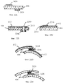
Фиг. 7А и 7В - схемы, иллюстрирующие плоскостное отображение примерных вариантов спиральных антенн со связанными сегментами. Фиг.7А иллюстрирует излучатель 706 с несколькими связанными сегментами, с разомкнутым выводом в соответствии с одним из однозаходных вариантов. Такая антенна с разомкнутым выводом может быть использована при выполнении антенны однозаходной, двухзаходной, четырехзаходной и другой х-заходной. FIG. 7A and 7B are diagrams illustrating a planar view of exemplary embodiments of helical antennas with associated segments. 7A illustrates an
Вариант, проиллюстрированный на фиг. 7А, состоит из одного излучателя 706. Излучатель 706 состоит из ряда излучательных сегментов. Этот ряд состоит из двух концевых сегментов 708, 710 и р промежуточных сегментов 712, где р=0, 1, 2, 3... (проиллюстрирован случай, когда р=3). Промежуточные сегменты являются необязательными (т.е. р может быть равно нулю). Концевые сегменты 708, 710 физически отделены друг от друга, но электромагнитно связаны друг с другом. Промежуточные сегменты 712 расположены между концевыми сегментами 708, 710 и обеспечивают электромагнитную связь между концевыми сегментами 708, 710. The embodiment illustrated in FIG. 7A, consists of a
В варианте с разомкнутым выводом длина ls1 сегмента 708 равна четверти длины волны требующейся резонансной частоты, умноженной на нечетное целое число. Длина ls2 сегмента 710 равна половине длины волны требующейся резонансной частоты, умноженной на целое число. Длина lsp каждого из р промежуточных сегментов 712 равна половине длины волны требующейся резонансной частоты, умноженной на целое число. В проиллюстрированном варианте имеется три промежуточных сегмента 712 (т.е. р=3).In the open-ended version, the length l s1 of the segment 708 is equal to a quarter of the wavelength of the required resonant frequency times an odd integer. The length l s2 of segment 710 is equal to half the wavelength of the required resonant frequency times an integer. The length l sp of each of the p
Фиг. 7В иллюстрирует излучатели 706 спиральной антенны, когда они оканчиваются короткозамкнутой цепью 722. Этот короткозамкнутый вариант выполнения излучателя не подходит для однозаходной антенны, но он может быть использован для двухзаходных, четырехзаходных или других х-заходных антенн. Как и в варианте с разомкнутым контуром, излучатели 706 состоят из ряда излучательных сегментов. Этот ряд состоит из двух концевых сегментов 708, 710 и р промежуточных сегментов 712, где р=0, 1, 2, 3... (проиллюстрирован случай, когда р=3). Промежуточные сегменты являются необязательными (т.е. р может быть равно нулю). Концевые сегменты 708, 710 физически отделены друг от друга, но электромагнитно связаны друг с другом. Промежуточные сегменты расположены между концевыми сегментами 708, 710 и обеспечивают электромагнитную связь между концевыми сегментами 708, 710. FIG. 7B illustrates
В короткозамкнутом варианте длина ls1 сегмента 708 равна умноженной на нечетное целое число четверти длины волны требующееся резонансной частоты. Длина ls2 сегмента 710 кратна нечетному целому четверти длины волны требующейся резонансчой частоты. Длина lsp каждого из р промежуточных сегментов 712 кратна целому половины длины волны требующейся резонансной частоты. В проиллюстрированном варианте имеется три промежуточных сегмента 712 (т.е. р=3).In the short-circuited embodiment, the length l s1 of the segment 708 is equal to the odd integer number of a quarter wavelength required by the resonant frequency. The length l s2 of segment 710 is a multiple of an odd whole quarter of the wavelength of the required resonant frequency. The length l sp of each of the p
Фиг. 8А и 8В - схемы, иллюстрирующие излучательную часть 800 четырехзаходной спиральной антенны с несколькими связанными сегментами в соответствии с одним из вариантов изобретения. Фиг.8А и 8В иллюстрируют одну примерную реализацию антенны, показанной на фиг.7В, где р=0 (т.е. промежуточные сегменты 712 отсутствуют), а длины сегментов 708, 710 равны четверти длины волны. FIG. 8A and 8B are diagrams illustrating a radiating
Излучательная часть 800, проиллюстрированная на фиг.8А, представляет собой плоскостное отображение четырехзаходной спиральной антенны, имеющей четыре связанных излучателя 804. Каждый связанный излучатель 804 в связанной антенне фактически состоит из двух излучательных сегментов 708, 710, расположенных вблизи друг от друга так, что энергия в излучательном сегменте 708 за счет электромагнитной связи связывается (переходит) с другим излучательным сегментом 710. The radiating
А более конкретно, согласно одному из вариантов излучательная часть 800 может быть описана как имеющая две секции 820, 824. Секция 820 состоит из множества излучательных сегментол 708, вытянутых от первого конца 832 излучательной части 800 в направлении второго конца 834 излучательной части 800. Секция 824 состоит из второго множества излучательных сегментов 710, вытянутых от второго конца 834 излучательной части 800 в направлении первого конца 832. В направлении к центральной области излучательной части 800 часть каждого сегмента 708 находится вблизи от примыкающего сегмента 710 так, что энергия из одного сегмента за счет электромагнитной связи поступает в соседний сегмент в области, где они близки. В настоящем документе эта область называется перекрытием. More specifically, in one embodiment, the radiating
В предпочтительном варианте каждый сегмент 708, 710 имеет длины приблизительно l1= λ/4. Полная длина одного излучателя, содержащего два сегмента 708, 710, определяется как ltot. Величина, на которую один сегмент 708 перекрывает другой сегмент 710, определяется как δ=l1+l2-ltot.In a preferred embodiment, each
Для резонансной частоты f=v/λ полная длина излучателя ltot меньше, чем половина длины волны λ/2. Другими словами, в результате связи (контуров) излучатель, содержащий пару связанных сегментов 708, 710, резонирует на частоте f=v/λ, даже несмотря на то, что полная длина этого излучателя меньше, чем длина λ/2. Таким образом, для заданной частоты f излучательная часть 800 1/2-волновой четырехзаходной спиральной антенны с несколькими связанными сегментами короче, чем излучательная часть обычной полуволновой четырехзаходной спиральной антенны 800.For the resonant frequency f = v / λ, the total emitter length l tot is less than half the wavelength λ / 2. In other words, as a result of coupling (circuits), the emitter containing a pair of
Для более наглядной иллюстрации уменьшения размера, получаемого при использовании связанной конфигурации, сравним излучательные части 800, показанные на фиг. 8, с излучательными частями, показанными на фиг.3. Для заданной частоты f=v/λ длина l излучательной части 300 обычной антенны равна λ/2, а длина ltot излучательной части 800 антенны со связанными излучательными сегментами меньше, чем λ/2.To more clearly illustrate the reduction in size obtained using the coupled configuration, compare the radiating
Как утверждалось выше, в одном из вариантов сегменты 708, 710 представляют собой длину l1=l2=λ/4. Длина каждого сегмента может варьироваться так, что l1 не обязательно равна l2, и так, что они не равны λ/4. Фактическая резонансная частота каждого излучателя является функцией от длины излучательных сегментов 708, 710, промежутка s между излучательными сегментами 708, 710 и величины, на которую сегменты 708, 710 перекрывают друг друга.As stated above, in one embodiment,
Заметим, что изменение длины одного сегмента 708 по отношению к другому сегменту 710 может быть использовано для настройки ширины частотной полосы антенны. Например, удлинняя l1 так, чтобы она была немного длиннее, чем λ/4, и укорачивая l2 так, чтобы она была немного короче, чем λ/4, можно увеличить ширину частотной полосы антенны.Note that changing the length of one
Фиг. 8В илллюстрирует действительную спиральную конфигурацию четырехзаходной спиральной антенны с несколькими связанными сегментами, соответствующую одному из вариантов изобретения. На фиг.8В показано, как в одном из вариантов каждый излучатель состоит из двух сегментов 708, 710. Сегмент 708 вытянут в спиральном виде от первого конца 832 излучательной части в направлении второго конца 834 излучательной части. Сегмент 710 вытянут в спиральном виде от второго конца 834 излучательной части в направлении первого конца 832 излучательной части. На фиг.8В также показано, что часть сегментов 708, 710 перекрывается так, что они электромагнитно связаны друг с другом. FIG. 8B illustrates the actual helical configuration of a four-way helical antenna with several connected segments, in accordance with one embodiment of the invention. Fig. 8B shows how, in one embodiment, each emitter consists of two
Фиг. 9А - схема, иллюстрирующая промежуток s и перекрытие δ между излучательными сегментами 708, 710. Промежуток s выбирается таким, чтобы количество энергии, которое бы связывалось между излучательными сегментами 708, 710, было бы достаточным для того, чтобы они функционировали как один излучатель с эффективной электрической длиной приблизительно λ/2 и длинами, равными этой длине, умноженной на целое число. FIG. 9A is a diagram illustrating the gap s and the overlap δ between the radiating
Промежуток между излучательными сегментами 708, 710 более узкий, чем этот оптимальный промежуток, приводит к увеличению связи между сегментами 708, 710. В результате для данной частоты f длина сегментов 708, 710 должна быть увеличена, чтобы обеспечить резонанс на той же частоте f. Это может быть проиллюстрировано с помощью предельного случая, когда сегменты 708, 710 физически соединены (т. е. s=0). В этом предельном случае полная длина сегментов 708, 710 должна быть равна λ/2 для того, чтобы антенна резонировала. Заметим, что в этом предельном случае антенна не длиннее реально "связанной" антенны согласно терминологии, употребляемой в настоящем описании, и результирующая конфигурация фактически является конфигурацией обычной спиральной антенны, такой, которая показана на фиг.3. The gap between the radiating
Аналогично увеличение величины перекрытия δ сегментов 708, 710 приводит к увеличению связи. Таким образом, при увеличении перекрытия δ длина сегментов 708, 710 также должна увеличиваться. Similarly, an increase in the overlap δ of
Для того чтобы качественно определить оптимальные величины перекрытия и промежутка для сегментов 708, 710, обратимся к фиг.9В. Фиг.9В представляет величину тока на каждом сегменте 708, 710. Указатели 911, 928 силы тока показывают, что каждый сегмент идеально резонирует на λ/4, при этом максимальный уровень сигнала на наружных концах и минимальный уровень на внутренних концах. In order to qualitatively determine the optimal values of the overlap and the gap for
Для оптимизации конфигураций антенны, для антенны со связанными излучательными сегментами изобретатели использовали моделирующую программу, чтобы определить правильные длины l1, l2 сегментов, перекрытие δ и промежуток s, а также другие параметры. Один из таких пакетов программ - это пакет программ "Оптимизатор антенны" (Antenna Optimizer) (ОА). ОА основан на методе алгоритмического моделирования электромагнитных моментов антенны. ОА Antenna Optimizer, версия 6.35, авторское право 1994 была записана и получена от Brian Beezley, Сан-Диего, Калифорния.To optimize antenna configurations, for an antenna with associated radiating segments, the inventors used a simulation program to determine the correct lengths of l 1 , l 2 segments, overlap δ and spacing s, as well as other parameters. One such software package is the Antenna Optimizer (OA) software package. OA is based on the method of algorithmic modeling of antenna electromagnetic moments. OA Antenna Optimizer, Version 6.35, copyright 1994 was recorded and obtained from Brian Beezley, San Diego, California.
Заметим, что имеются определенные достоинства, получаемые за счет использования связанной конфигурации, как описано выше со ссылкой на фиг.8А и 8В. В обеих антеннах, в обычной антенне и антенне со связанными излучательными сегментами, ток концентрируется на концах излучателей. В соответствии с теорией множителя решетки это может быть использовано для получения преимуществ в определенных приложениях при наличии антенны со связанными излучательными сегментами. Note that there are certain advantages obtained by using the associated configuration, as described above with reference to figa and 8B. In both antennas, in a conventional antenna and an antenna with associated radiating segments, the current is concentrated at the ends of the emitters. In accordance with the theory of the grating factor, this can be used to obtain advantages in certain applications in the presence of an antenna with associated radiating segments.
Для пояснения: фиг.10А - схема, иллюстрирующая два точечных источника А, В, где источник А излучает сигнал, имеющий амплитуду, равную амплитуде сигнала от источника В, но сигнал, сдвинутый по фазе на 90o (предполагается еjwt). Когда источники А и В разделены расстоянием λ/4, сигналы складываются синфазно в направлении распространения от А к В и складываются в противофазе в направлении от В к А. В результате в направлении от В к А испускается очень небольшое излучение. Типичная характерная диаграмма направленности для напряженности поля, показанная на фиг.10В, иллюстрирует этот момент.For clarification: FIG. 10A is a diagram illustrating two point sources A, B, where source A emits a signal having an amplitude equal to the amplitude of the signal from source B, but the signal is 90 o phase-shifted (assumed e jwt ). When the sources A and B are separated by a distance of λ / 4, the signals are added in phase in the direction of propagation from A to B and added in antiphase in the direction from B to A. As a result, very little radiation is emitted in the direction from B to A. A typical representative radiation pattern for field strength shown in FIG. 10B illustrates this point.
Следовательно, когда источники А и В ориентированы так, что направление от А к В указывает вверх, от земли, а направление от В к А указывает к земле, антенна является оптимизированной для большинства приложений. Это потому, что пользователю редко требуется антенна, которая направляет силу сигнала к земле. Такая конфигурация особенно полезна для спутниковых систем связи, где требуется, чтобы большая часть силы сигнала была направлена вверх, от земли. Therefore, when sources A and B are oriented so that the direction from A to B points up, from the ground, and the direction from B to A points to the ground, the antenna is optimized for most applications. This is because the user rarely needs an antenna that directs signal strength to ground. This configuration is especially useful for satellite communications systems where it is required that most of the signal strength is directed upward from the ground.
Антенна с точечными источниками, модель которой показана на фиг.10А, не без труда может быть получена с использованием обычной полуволновой спиральной антенны. Рассмотрим излучательную часть антенны, показанную на фиг. 3. Концентрация силы тока на концах излучателей 208 грубо аппроксимирует точечный источник. Когда излучатели скручены в спиральную конфигурацию, один конец 90o излучателя располагается на одной линии с другим концом 0o излучателя. Следовательно, это аппроксимирует два точечных источника на одной линии. Однако такие аппроксимированные точечные источники отделены друг от друга расстоянием примерно λ/2 в отличие от требующейся конфигурации λ/4, проиллюстрированной на фиг.10А.An antenna with point sources, the model of which is shown in Fig. 10A, can be easily obtained using a conventional half-wave helical antenna. Consider the radiative part of the antenna shown in FIG. 3. The concentration of current at the ends of the
Заметим, однако, что выполняя антенну со связанными излучательными сегментами, изобретение обеспечивает реализацию случая, когда аппроксимированные точечные источники находятся на расстоянии друг от друга более близком, чем λ/4. Таким образом, антенна со связанными излучательными сегментами позволяет пользователям использовать для своей выгоды диаграммы направленности антенны, проиллюстрированные на фиг.10А. We note, however, that by performing an antenna with associated radiating segments, the invention provides a case where the approximated point sources are closer to each other than λ / 4. Thus, an antenna with associated radiating segments allows users to take advantage of the antenna patterns illustrated in FIG. 10A.
Излучательные сегменты 708, 710, проиллюстрированные на фиг.8, показывают, что сегмент 708 находится очень близко к связанному с ним сегменту 710, кроме того, каждая пара сегментов 708, 710 находится относительно далеко от соседней пары сегментов. В одном из альтернативных вариантов каждый сегмент 710 размещен эквидистантно от сегментов 708 с обеих сторон. Такой вариант проиллюстрирован на фиг.11. The radiating
Обратимся теперь к фиг. 11; каждый сегмент, по существу, находится на равном расстоянии от каждой пары соседних сегментов. Например, сегмент 708В на равном расстоянии от сегментов 710А, 710В. То есть s1=s2. Аналогично сегмент 710А находится на равном расстоянии от сегментов 708А, 708В.Turning now to FIG. eleven; each segment is substantially equidistant from each pair of adjacent segments. For example,
Этот вариант противоречит интуитивному представлению, что в этом случае как будто будет существовать нежелательная связь. Другими словами, сегмент, соответствующий одной фазе, будет связан не только с соответствующим сегментом с такой же фазой, но также и с соседним сегментом со смещенной фазой. Например, сегмент 708В, сегмент с фазой 90o, будет связан с сегментом 710А (сегмент 0o) и сегментом 710В (сегмент 90o). Такая связь не представляет проблему, потому что излучение из верхних сегментов 710 можно рассматривать как две отдельные моды. Одна мода возникает в результате связи с соседними сегментами, находящимися слева, а другая мода - из связи с соседними сегментами справа. Однако обе эти моды имеют такие фазы, что они обеспечивают излучение в одном и том же направлении. Таким образом, эта двойная связь не причиняет вреда работе антенны с несколькими связанными сегментами.This option contradicts the intuitive idea that in this case it would seem that there would be an undesirable relationship. In other words, the segment corresponding to one phase will be associated not only with the corresponding segment with the same phase, but also with the adjacent segment with the shifted phase. For example,
Фиг. 12 - схема, иллюстрирующая примерную реализацию антенны со связанными излучательными сегментами. Обратимся теперь к фиг.12; антенна содержит излучательную часть 1202 и возбуждающую часть 1206. Излучательная часть включает сегменты 708, 710. Размеры, показанные на фиг.12, иллюстрируют вклад сегментов 708, 710 и величины перекрытия δ в полную длину излучательной части 1202. FIG. 12 is a diagram illustrating an exemplary implementation of an antenna with associated radiating segments. Turning now to FIG. 12; the antenna comprises a radiating part 1202 and a
Длина сегментов в направлении, параллельном оси цилиндра, обозначена как l1sinα для сегмента 708 и l2sinα для сегментов 710, где α - внутренний угол сегментов 708, 710.The length of the segments in the direction parallel to the axis of the cylinder is indicated as l 1 sinα for
Перекрытие сегментов, которое проиллюстрировано выше на фиг.8А и 9А, обозначено буквенной позицией δ. Как показано на фиг.12, величина перекрытия в направлении, параллельном оси антенны, определяется как δsinα. The overlap of the segments, which is illustrated above in FIGS. 8A and 9A, is indicated by the letter position δ. As shown in FIG. 12, the amount of overlap in the direction parallel to the axis of the antenna is defined as δsinα.
Сегменты 708, 710 разделены промежутком s, который может варьироваться, как описано выше. Расстояние между концом сегмента 708, 710 и концом излучательной части 1202 определяется как зазор и обозначено буквенными позициями γ1,γ2, соответственно. Зазоры γ1,γ2 могут, но не обязательно должны, быть равны друг другу. И опять, как описано выше, длина сегментов 708 может изменяться относительно длины сегментов 710.
Величина смещения сегмента 710 от одного конца к следующему проиллюстрирована буквенной позицией ω0. Расстояние между соседними сегментами 710 проиллюстрировано буквенной
позицией ωs и определяется оно диаметром спирали.The amount of displacement of the
position ω s and it is determined by the diameter of the spiral.
Возбуждающая часть 1206 включает соответствующую схему возбуждения для формирования и подачи квадратурных сигналов на излучительные сегменты 708. Средним специалистам в данной области техники схемы возбуждения хорошо известны и поэтому подробно они здесь не описаны. The
В примере, проиллюстрированном на фиг. 12, на сегменты 708 подается сигнал в точке возбуждения, которая расположена вдоль каждого сегмента 708 на расстоянии от схемы возбуждения, которое выбирается оптимальным для согласования импедансов. В варианте, проиллюстрированном на фиг.12, это расстояние обозначено буквенной позицией δfeed.In the example illustrated in FIG. 12, a signal is supplied to the
Заметим, что сплошная линия 1224 иллюстрирует границу заземленной части на дальней поверхности основы. Заземленная часть, находящаяся напротив сегментов 708 на дальней поверхности, вытянута к точке возбуждения. Тонкая часть сегментов 708 находится на ближней поверхности. В точке возбуждения толщина сегментов 708 на ближней поверхности увеличивается. Note that the
Теперь представлены размеры для примерной четырехзаходной спиральной антенны со связанными излучательными сегментами, подходящими для работы в L-диапазоне на частоте примерно 1.6 ГГц. Заметим, что это только пример и для работы в L-диапазоне возможны и другие размеры. Кроме того, для других частотных диапазонов также возможны другие размеры. The dimensions are now presented for an exemplary four-way helical antenna with associated radiating segments suitable for operation in the L-band at a frequency of about 1.6 GHz. Note that this is just an example and other sizes are possible for working in the L-band. In addition, other sizes are also possible for other frequency ranges.
Полная длина излучательной части 1202 в примерном варианте с L-диапазоном 2.30 дюймов (58.4 мм). В этом варианте угол α наклона 73o. При этом угле α длина сегментов 708 l1sinα для этого варианта составляет 1.73 дюйма (43.9 мм). В показанном варианте длина сегментов 710 равна длине сегментов 708.The total length of the radiating part 1202 in an exemplary embodiment with an L-band of 2.30 inches (58.4 mm). In this embodiment, the inclination angle α is 73 ° . At this angle α, the segment length of 708 l 1 sinα for this option is 1.73 inches (43.9 mm). In the shown embodiment, the length of the
В одном из примеров сегмент 710 расположен, по существу, на одинаковом расстоянии от ближайшей пары сегментов 708. В одной из реализации этого варианта, где сегменты 710 на одинаковом расстоянии от соседних сегментов 708, промежуток s1=s2=0.086 дюймов (2.2 мм). Возможны и другие промежутки, включая, например, промежуток s в 0.070 дюймов (1.8 мм) от сегментов 710 до ближайшего сегмента 708.In one example,
В этом варианте ширина τ излучательных сегментов 708, 710 составляет 0.11 дюймов (2.8 мм). Возможны и другие величины ширины. In this embodiment, the width τ of the radiating
В примерном варианте антенны L-диапазона симметричный зазор γ1=γ2=0.57 дюймов (14.5 мм). Когда зазор γ является симметричным для обоих концов излучательной части 1202 (т.е. когда γ1 = γ2), излучатели 708, 710 имеют перекрытие δsinα, равное 1.16 дюймов (29.5 мм) (1.73 дюйма - 0.57 дюймов) (44.5 мм - 14.5 мм).In an exemplary embodiment of the L-band antenna, the symmetric gap is γ 1 = γ 2 = 0.57 inches (14.5 mm). When the gap γ is symmetrical for both ends of the radiating part 1202 (i.e., when γ 1 = γ 2 ), the
Отклонение ωo сегмента составляет 0.53 дюйма (13.2 мм), а промежуток ωs между сегментами 0.393 дюйма (10.0 мм). Диаметр антенны 4ωs/π.The deviation ω o of the segment is 0.53 inches (13.2 mm), and the gap ω s between the segments is 0.393 inches (10.0 mm). The diameter of the antenna is 4ω s / π.
В одном из вариантов это выбирается так, чтобы расстояние δfeed от точки возбуждения до схемы возбуждения было равно δfeed=1.57 дюймов (39.9 мм). Для оптимального согласования импедансов могут быть выбраны и другие точки возбуждения.In one embodiment, this is selected so that the distance δ feed from the excitation point to the excitation circuit is equal to δ feed = 1.57 inches (39.9 mm). For optimal impedance matching, other excitation points can be selected.
Заметим, что примерный вариант, описанный выше, сконструирован для использования в сочетании с поликарбонатным обтекателем толщиной 0.032 дюймовым (0.81 мм), окружающим спиральную антенну и контактирующим с излучательной частью. Специалисту в данной области техники станет очевидным, как обтекатель или другая конструкция влияет на длину волны требующейся частоты. Note that the exemplary embodiment described above is designed to be used in conjunction with a 0.032 inch (0.81 mm) thick polycarbonate fairing surrounding a helical antenna and in contact with the radiating portion. It will become apparent to those skilled in the art how a cowl or other structure affects the wavelength of a desired frequency.
Заметим, что в только что описанных примерных вариантах полная длина излучательной части антенны L-диапазона уменьшена по сравнению с обычной полуволновой антенной L-диапазона. Для обычной полуволновой антенны L-диапазона длина излучательной части приблизительно 3.2 дюйма (т.е. λ/2(sinα), где α - внутренний угол сегментов 708, 710 относительно горизонтали) или 81.3 мм. Для примерных вариантов, описанных выше, полная длина излучательной части 1202 2.3 дюйма (58.42 мм). Это дает существенную экономию в размере по сравнению с обычной антенной. Note that in the exemplary embodiments just described, the total length of the radiating part of the L-band antenna is reduced compared to a conventional half-wave L-band antenna. For a typical L-band half-wave antenna, the length of the radiating part is approximately 3.2 inches (i.e., λ / 2 (sinα), where α is the internal angle of the
V. Ярусная составная двухдиапазонная спиральная антенна
Теперь после описания нескольких вариантов однодиапазонной спиральной антенны будет описана двухдиапазонная спиральная антенна, в которой реализуется настоящее изобретение. Настоящее изобретение направлено на создание двухдиапазонной спиральной антенны, способной резонировать на двух различных рабочих частотах. Две спиральные антенны составляются ярусно торец к торцу, при этом одна антенна резонирует на первой частоте, а другая антенна резонирует на второй частоте. Каждая антенна имеет излучательную часть, состоящую из одного или нескольких спирально скрученных излучателей. Каждая антенна также имеет возбуждающую часть, состоящую из схемы возбуждения и заземленного слоя. Две антенны ярусно составлены так, что заземленный слой первой антенны используется в качестве короткозамыкающего кольца по дальнему концу излучателей другой антенны.V. Longline composite dual-band helical antenna
Now, after describing several options for a single-band helical antenna, a dual-band helical antenna in which the present invention is implemented will be described. The present invention is directed to a dual-band helical antenna capable of resonating at two different operating frequencies. Two helical antennas are composed tier end to end, with one antenna resonating at the first frequency, and the other antenna resonating at the second frequency. Each antenna has a radiating part, consisting of one or more helically twisted emitters. Each antenna also has an excitation part consisting of an excitation circuit and a ground plane. The two antennas are tiered in such a way that the ground plane of the first antenna is used as a short-circuit ring at the far end of the radiators of the other antenna.
Фиг. 13 - схема, иллюстрирующая плоскостное отображение дальней поверхности 400 и ближней поверхности 500 двухдиапазонной спиральной антенны, согласно одному из вариантов изобретения. Двухдиапазонная спиральная антенна состоит из двух однодиапазонных спиральных антенн: спиральной антенны 1304, работающей на первой резонансной частоте, и спиральной антенны 1308, работающей на второй резонансной частоте. FIG. 13 is a diagram illustrating a planar display of a
В варианте, проиллюстрированном на фиг.13, схема возбуждения 508, излучатели 104А-104D первой антенны 1304 расположены на ближней поверхности 500 первой антенны. Кроме того, на ближней поверхности 500 расположен заземленный слой 412 для схемы возбуждения 508 второй антенны 1308. На дальней поверхности 400 находятся схема возбуждения 508 и излучатели 104А-104D второй антенны 1308, а также заземленный слой 412 для возбуждающей части первой антенны 1304. In the embodiment illustrated in FIG. 13, the
Как обсуждалось выше со ссылкой на фиг.2А и 2В, когда резонансная длина l излучателей 104А-104D кратна четверти длины волны требующейся резонансной частоты, с четным целым кратным, дальний конец излучателей 104А-104D коротко замкнут. Как показано на фиг.13, это закорачивание выполняется, используя заземленный слой 412 первой антенны 1304. В результате при такой конфигурации не требуется добавлять к концу излучателей 104А-104D дополнительного закорачивающего кольца. As discussed above with reference to FIGS. 2A and 2B, when the resonant length l of the
Заметим, что в варианте, показанном на фиг.13, первая антенна 1304 показана как антенна, резонирующая при длине, кратной четверти длины волны требующейся резонансной частоты, с нечетным целым кратным, поскольку концы излучателей 104А-104D разомкнуты. В альтернативном варианте закорачивающее кольцо (не показано) может быть добавлено к дальнему концу излучателей 104А-104D первой антенны 1304, но с изменением длины этих излучателей 104А-104D так, чтобы они были по длине кратны четверти длины волны требующейся резонансной частоты, с четным целым кратным. Note that in the embodiment shown in FIG. 13, the
Излучатели 104А-104D двухдиапазонной антенны, описанной со ссылкой на фиг. 13, показаны как излучатели, возбуждаемые на первом конце около схемы возбуждения 508. Хорошо известно, что точка возбуждения излучателей 104А-104D спиральной антенны может быть расположена в любом месте вдоль длины излучателей 104А-104D, ее расположение в первую очередь определяется исходя из согласования импедансов. Фиг.14 - схема, иллюстрирующая один из вариантов двухдиапазонной спиральной антенны, в которой точки возбуждения излучателей 104А-104D расположены на заданном расстоянии от схемы возбуждения 508. А конкретно, в варианте, показанном на фиг.14, точка А возбуждения первой антенны 1304 расположена на расстоянии lFEED1 схемы 508 возбуждения, а точка В возбуждения второй антенны 1308 расположена на расстоянии lFEED2 от схемы 508 возбуждения.The dual-
Этот вариант иллюстрирует, что излучатели 104А-104D состоят из заземленной дорожки 1436 на первой поверхности основы 406, дорожки 1438 подачи сигнала возбуждения на второй поверхности основы 406 и находящейся напротив (с противоположной стороны) упомянутой заземленной дорожки 1436, и излучательной дорожки 1440 на второй поверхности основы 406. This embodiment illustrates that
Как и в варианте, показанном на фиг.13, в этом варианте заземленный слой 412 первой антенны 1304 служит закорачивающим кольцом для излучателей 104А-104D второй антенны 1308 так, что излучатели второй антенны 1308 резонируют на длине, кратной четверти длины волны требующейся резонансном частоты, с четным целым кратным. As in the embodiment shown in FIG. 13, in this embodiment, the
Для того чтобы уменьшить полную длину ярусной составной антенны, может быть использована обсуждавшаяся выше конструкция со связанными (электромагнитно) краями. В таких вариантах излучатели 104А-104D первой антенны 1304 и/или второй антенны 1308, которые показаны на фиг.13 и 14, заменяются на излучатели со связанными краями, которые показаны, например, на фиг.12. In order to reduce the total length of the longline composite antenna, the design discussed above with associated (electromagnetic) edges can be used. In such embodiments,
Одна из проблем при создании двухдиапазонной антенны, такой как показана на фиг.13 и 14, заключается в возбуждении первой антенны 1304. Для этого первая антенна 1304 возбуждается (запитывается) с помощью контакта, выходящего из нижней зоны возбуждающей части первой антенны 1304. One of the problems in creating a dual-band antenna, such as shown in FIGS. 13 and 14, is to excite the
Фиг. 15 - схема, иллюстрирующая такой контакт, используемый для подачи сигнала на первую антенну 1304. Обратимся теперь к фиг.15; контакт 1504 вытянут с боковой стороны возбуждающей части первой антенны 1304 на основе 406. В варианте, показанном на фиг.15, контакт 1504 приблизительно имеет "L"-образную форму так, что он вытянут горизонтально от возбуждающей части первой антенны 1304 на заданное расстояние, а затем поворачивается под углом, проходит аксиально через центр в направлении возбуждающей части второй антенны 1308. Несмотря на то, что контакт 1504 показан, как имеющий форму прямого угла, могут быть использованы другие углы, а также кривые с различными радиусами (кривизны). FIG. 15 is a diagram illustrating such a contact used to supply a signal to a
В идеальном случае, когда основа 406 скручена в цилиндр или другую соответствующую форму для образования спиральной антенны, осевая составляющая 1524 контакта 1504, по существу, располагается вдоль оси двухдиапазонной спиральной антенны. Когда осевая составляющая 1524 контакта 1504 совпадает с осью спиральной антенны, то этот элемент оказывает минимальное влияние на диаграмму направленности антенны. Как показано на фиг.15, в предпочтительном варианте контакт 1504 вытянут от возбуждающей части первой антенны 1304 в вертикальном положении, т. е. как можно дальше от первой антенны 1304. Это сделано для того, чтобы минимизировать влияние контакта 1504 на диаграмму направленности первой антенны 1304. Поскольку вторая антенна 1308 представляет собой полуволновую антенну со связанными сегментами и концы излучателей 104А-104D второй антенны 1308 коротко замкнуты заземленным слоем 412 первой антенны 1304, контакт 1504 имеет минимальное влияние на диаграмму направленности второй антенны 1308. Ideally, when the
Предпочтительно длина lgp возбуждающей части 1206 первой антенны 1304 может определяться, учитывая два фактора, при соответствующей рабочей частоте. Во-первых, желательно минимизировать величину тока, протекающего от излучателей первой антенны 1304 во вторую антенну 1308 и наоборот. Другими словами, желательно, чтобы две антенны были изолированы друг от друга. Это можно осуществить с помощью выбора длины; если длина будет настолько большая, чтобы токи на интересующей частоте не доходили от одной группы излучателей до другой.Preferably, the length l gp of the driving portion 1206 of the
Другая проблема - это решение задачи, направленной на то, чтобы токи из излучателей 104A-D первой антенны 1304 не смогли достигнуть контакта 1504. Токи из первой антенны 1304 ослабляются по мере того, как они проходят через возбуждающую часть первой антенны 1304 к контакту 1504. Контакт 1504 создает асимметричную неоднородность в этих токах. Поэтому требуется минимизировать величину токов, достигающих контакта 1504, до такой степени, чтобы антенну можно было применять на практике. Another problem is to solve the problem of preventing currents from
После прочтения этого описания специалистам в данной области техники станет очевидным, как выполнить возбуждающую часть 1206 соответствующей длины lgp, исходя из используемых материалов, интересующих частот, предполагаемых уровней мощности антенны и других известных факторов. Такое решение может также привести к компромиссному выбору между размером и рабочими параметрами.After reading this description, it will become apparent to those skilled in the art how to produce an
Заметим, что в этом варианте влияние контакта 1504 не является несущественным. Поскольку контакт 1504 находится вблизи от излучателей второй антенны 1308, часть тока из второй антенны 1308 электромагнитным путем связывается с контактом 1504 и поэтому проходит вдоль оси антенны. Этот ток влияет на излучение второй антенны 1308, приводя к увеличению излучения в боковые стороны антенны. Для применений, где антенна устанавливается вертикально, это приводит к увеличению излучения в горизонтальном направлении и уменьшению излучения в вертикальном направлении. Вследствие этого такая антенна хорошо подходит для систем спутниковой связи, где для передачи информации из или в устройство связи используются спутники на низкой околоземной орбите. Note that in this embodiment, the effect of
Этот эффект проиллюстрирован на фиг.10С, где диаграмма 1010 направленности с круговой поляризацией - это представление типичной диаграммы направленности для обычной спиральной антенны, а диаграмма 1020 направленности - это представление диаграммы направленности для второй антенны 1308. Как показано на фиг. 10С, диаграмма 1020 направленности более "плоская" и более "широкая", чем обычная диаграмма 1010 направленности антенны. This effect is illustrated in FIG. 10C, where the circularly polarized
Для обеспечения поступления сигнала на первую антенну 1304 контакт 1504 включает соединитель, такой как обжимной соединитель, или паянный соединитель, или другой соединитель, подходящий для выполнения соединения между кабелем питания и сигнальной дорожкой на контакте 1504. Для подсоединения РЧ-приемопередающего устройства к антенне в месте контакта 1504 могут использоваться различные типы кабелей или проволоки. Предпочтительно используется гибкий или полужесткий кабель с низкими потерями. Конечно, хорошо известно из соответствующего уровня техники, что для передачи в антенну максимальной мощности требуется согласовать импеданс входа схемы возбуждения с импедансом стыка кабеля. Однако если входной переход плохой, то диаграммы направленности будут оставаться симметричными, но более низкими будут коэффициенты направленного действия антенны в соответствии в величинами потерь мощности из-за отражения сигнала. Помимо низких потерь (мощности) при вводе важно также, чтобы соединитель обеспечивал прочное механическое соединение между кабелем и контактом 1504. To provide a signal to the
На фиг.15 также показан контур для примерной формы основы. После прочтения этого описания специалистам в данной области техники станет очевидным, как выполнить антенну с контактом 1504, используя основы, которые имеют другие формы. 15 also shows a contour for an exemplary base shape. After reading this description, it will become apparent to those skilled in the art how to make an antenna with
Фиг.16 - схема, иллюстрирующая один из вариантов ярусной составной антенны с примерными размерами. В этом варианте первая антенна 1304 представляет собой антенну L-диапазона, а вторая антенна 1308 представляет собой антенну S-диапазона. В этом варианте антенна 1308 S-диапазона является антенной со связанными краями, в которой каждый излучатель 104 состоит из двух сегментов. Заметим, что этот вариант приведен только для примера. Для работы могут быть выбраны и другие частотные диапазоны. Также заметим, что первая антенна 1304 или вторая антенна 1308 или обе антенны могут быть выполнены по технологии антенны со связанными краями. 16 is a diagram illustrating one embodiment of a longline composite antenna with approximate dimensions. In this embodiment, the
Теперь будут описаны примерные размеры для антенны L-диапазона и S-диапазона, проиллюстрированной на фиг.16. Излучающая апертура антенны L-диапазона - это полная высота по оси 1.253 дюймов (21.8 мм), а апертура S-диапазона - это полная высота 1.400 дюйма (35.7 мм). В этом варианте высота возбуждающей части 412 первой антенны 1304 0.400 дюйма (10.2 мм). Это дает полную (суммарную) излучающую апертуру антенны 3.093 дюйма (67.7 мм). Угол наклона излучателей 104А-104D 65o.Exemplary sizes for the L-band and S-band antennas illustrated in FIG. 16 will now be described. The radiating aperture of the L-band antenna is the total height along the axis of 1.253 inches (21.8 mm), and the S-aperture is the total height of 1.400 inches (35.7 mm). In this embodiment, the height of the
Вышеуказанные размеры приведены только для примера. Как уже обсуждалось выше со ссылкой на обычную спиральную антенну, полная длина излучателей 104А-104D определяет точную частоту, на которой резонирует антенна. Резонансная частота важна, поскольку наивысшие усредненные коэффициенты усиления (направленного действия) антенны и наиболее симметричные диаграммы направленности антенны получаются на резонансной частоте. Если антенна выполнена более длинной, то резонансная частота смещается вниз. И напротив, если антенна выполнена более короткой, то резонансная частота смещается вверх. В процентах смещение частоты приблизительно пропорционально удлинению или укорочению излучателей 104А-104D, выраженному в процентах. На рабочих частотах L-диапазона грубая оценка следующая: 1 мм длины в направленности оси антенны соответствует 1 МГц. The above dimensions are for reference only. As discussed above with reference to a conventional helical antenna, the total length of the
В проиллюстрированном варианте и первая антенна 1304, и вторая антенна 1308 имеют по четыре возбуждаемых нитевидных элемента или излучателей 104А-104D. На каждый из этих излучателей подается сигнал в фазовой квадратуре. Квадратурное возбуждение четырех излучателей 104А-104D для каждой антенны 1304, 1308 осуществляется, используя схему возбуждения. Несмотря на то, что могут быть реализованы обычные схемы возбуждения, обеспечивающие квадратурное фазовое возбуждение, ниже подробно обсуждается предпочтительная схема возбуждения. In the illustrated embodiment, both the
Другой важный размер - это осевая длина точки возбуждения (питания). Осевая длина точки возбуждения определяет расстояние от схемы возбуждения до точки возбуждения для вариантов, в которых точка возбуждения расположена вдоль излучателей 104А - 104D, как показано на фиг.13. Размер осевой длины точки возбуждения указывает на место, в котором микрополоска расширяется раструбом для продолжения излучателя, и это фактически место точки возбуждения для всего излучателя 104. В примере, показанном на фиг.16, длина точки возбуждения для первой антенны 1304 1.133 дюйма (28.8 мм). Длина точки возбуждения для второй антенны 1308 0.638 дюймов (17.2 мм). Эти размеры дают импедансы по 50 Ом на частотах 1618 и 2492 МГц соответственно. Если место точки возбуждения смещено вниз, то импеданс уменьшается. И, наоборот, если место точки возбуждения смещено вверх, то импеданс увеличивается. Важно заметить, что когда полная длина излучателя регулируется для настройки частоты, место точки возбуждения также должно смещаться на пропорциональную величину в направлении вдоль оси антенны, чтобы сохранить правильное согласование импедансов. Another important dimension is the axial length of the excitation (supply) point. The axial length of the drive point determines the distance from the drive circuit to the drive point for options in which the drive point is located along
Предпочтительно антенна, имеющая размеры, показанные на фиг.16, скатывается в цилиндр, имеющий диаметр 0.500 дюймов (12.7 мм). Preferably, the antenna having the dimensions shown in FIG. 16 is rolled into a cylinder having a diameter of 0.500 inches (12.7 mm).
VI. Схема возбуждения
Описанные спиральные антенны могут быть реализованы, используя однозаходную, четырехзаходную, восьмизаходную или другую х-заходную конфигурацию. Схема возбуждения используется для подачи на эти нитевидные элементы сигналов с необходимым фазовым углом. Схема возбуждения расщепляет сигнал и сдвигает по фазе, формируя сигнал для каждого элемента. Конфигурация схемы возбуждения зависит от числа нитевидных элементов. Например, для четырехзаходной спиральной антенны схема возбуждения обеспечивает четыре сигнала равной мощности с квадратурной фазовой взаимосвязью (т.е. 0, 90, 180 и 270o).VI. Excitation circuit
The described helical antennas can be implemented using a single-input, four-input, eight-input or other x-input configuration. The excitation circuit is used to supply signals with the necessary phase angle to these filamentary elements. The excitation circuit splits the signal and shifts in phase, forming a signal for each element. The configuration of the excitation circuit depends on the number of filiform elements. For example, for a four-way helical antenna, the drive circuit provides four signals of equal power with a quadrature phase relationship (i.e., 0, 90, 180, and 270 ° ).
Для экономии пространства на возбуждающей части антенны может использоваться уникальная конфигурация схемы возбуждения. Дорожки схемы возбуждения входят в один или несколько излучателей 104А-104D антенны. Для удобства описана схема возбуждения в применении к схеме возбуждения, выполненной для формирования четырех сигналов одинаковой мощности с квадратурной фазовой взаимосвязью. После прочтения настоящего описания специалисту в данной области техники станет очевидным, как выполнить схему возбуждения для других х-заходных конфигураций. To save space on the exciting part of the antenna, a unique configuration of the drive circuit can be used. The paths of the drive circuit are included in one or
Фиг.17 иллюстрирует электрическую эквивалентную схему обычной схемы квадратурного возбуждения. Для обычной схемы квадратурного возбуждения такая схема формирует четыре сигнала равной мощности, каждый из которых смещен по фазе на 90o. Сигнал подается на схему возбуждения по первому сигнальному пути (токопроводящей дорожке) 1704. В первой сигнальной точке А (называется вторичной точкой возбуждения) сигнал с фазой 0o подается на первый излучатель 104. В сигнальной точке В сигнал с фазой 90o подается на второй излучатель 104. В сигнальных точках С и D сигналы с фазами 180 и 270o подаются на третий и четвертый излучатели 104.17 illustrates an electrical equivalent circuit of a conventional quadrature drive circuit. For a conventional quadrature excitation circuit, such a circuit generates four signals of equal power, each of which is 90 ° out of phase. The signal is supplied to the excitation circuit along the first signal path (conductive path) 1704. At the first signal point A (called the secondary excitation point), the signal with phase 0 o is supplied to the
Сигналы А и В суммируются в точке Р2, чтобы получить импеданс 25 Ом. Аналогично сигналы С и D суммируются в точке Р3, чтобы получить импеданс 25 Ом. Эти сигналы суммируются в P1, чтобы получить импеданс 12.5 Ом. Поэтому на входе размещается преобразователь (трансформатор) 25 Ом, 90o для преобразования этого импеданса в 50 Ом. Заметим, что в схеме, показанной на фиг. 17, часть преобразователя размещена перед расщеплением Р1, чтобы укоротить схему возбуждения, а также уменьшить потери. Однако поскольку он расположен перед расщеплением, то после расщепления импеданс должен быть увеличен в два раза.Signals A and B are summed at point P2 to obtain an impedance of 25 ohms. Similarly, signals C and D are summed at point P3 to obtain an impedance of 25 ohms. These signals are summed in P1 to get an impedance of 12.5 ohms. Therefore, a converter (transformer) of 25 Ohms, 90 o is placed at the input to convert this impedance to 50 Ohms. Note that in the circuit shown in FIG. 17, a transducer portion is placed before splitting P1 to shorten the drive circuit and also reduce losses. However, since it is located before the splitting, after the splitting, the impedance should be doubled.
Обычная схема возбуждения видоизменена так, что дорожки схемы возбуждения расположены на частях основы, определенных для излучателей 104А-104D. А конкретно, в предпочтительном варианте эти токопроводящие дорожки расположены на основе в области, которая находится напротив (на противоположной стороне) заземленных дорожек одного или нескольких излучателей 104А-104D. The conventional drive circuit is modified so that the paths of the drive circuit are located on parts of the substrate defined for
Фиг.18 - это схема, иллюстрирующая примерный вариант схемы возбуждения в применении к четырехзаходной спиральной антенне. А конкретно, в примере, проиллюстрированном на фиг.18, показаны две схемы возбуждения: первая схема 1804 возбуждения для реализации с первой антенной 1304; и вторая схема 1808 возбуждения для реализации со второй антенной 1308. Схемы возбуждения 1804, 1808 имеют точки А, В, С и D для подачи на излучатели 104А-104D сигналов с фазой 0, 90, 180 и 270o. Штриховые линии на фиг.18 приблизительно иллюстрируют контур для заземленного слоя излучателей 104А-104D на поверхности основы напротив поверхности, на которой расположены схемы возбуждения 1804, 1808. Таким образом, фиг.18 иллюстрирует те участки схем возбуждения 1804, 1808, которые расположены на излучателях 104А-104D или входят в них.18 is a diagram illustrating an exemplary embodiment of an excitation circuit as applied to a four-way helical antenna. Specifically, in the example illustrated in FIG. 18, two drive circuits are shown: a
Заметим, что исходя из обычного здравого смысла схема возбуждения формируется в области, которая отделена от излучателей. И напротив, в показанном варианте схема возбуждения скомпонована так, что часть схемы возбуждения расположена на излучательной части антенны. Благодаря этому возбуждающая часть антенны может быть уменьшена в размере по сравнению с возбуждающей частью для обычных схем возбуждения. Note that, based on ordinary common sense, an excitation circuit is formed in a region that is separated from the emitters. Conversely, in the embodiment shown, the drive circuit is arranged such that a portion of the drive circuit is located on the radiative portion of the antenna. Due to this, the exciting part of the antenna can be reduced in size compared with the exciting part for conventional driving circuits.
Фиг. 19 - схема, иллюстрирующая схемы возбуждения 1804, 1808 вместе с сигнальными дорожками, включая токопроводящие дорожки питания, для антенн 1304, 1308. Фиг. 20 иллюстрирует контур для заземленного слоя антенн 1304, 1308. Фиг. 21 - схема, иллюстрирующая наложенные заземленные слои и сигнальные дорожки. FIG. 19 is a diagram illustrating
Достоинство этих схем возбуждения заключается в том, что область, требующаяся для возбуждающей части антенны, чтобы выполнить схему возбуждения, уменьшена по сравнению с обычными технологиями выполнения возбуждения. Это потому, что части схемы возбуждения антенны теперь размещены на излучательной части антенны. Вследствие этого полная длина антенны может быть уменьшена. The advantage of these drive circuits is that the area required for the drive portion of the antenna to perform the drive circuit is reduced compared to conventional drive technologies. This is because parts of the antenna drive circuit are now located on the radiative part of the antenna. As a result, the overall length of the antenna can be reduced.
Дополнительное достоинство такой схемы возбуждения состоит в том, что, поскольку вторичная точка возбуждения сдвинута ближе к точке возбуждения антенны, потери в линии передачи уменьшены. Кроме того, преобразователь может быть интегрирован в линию "трассы" схемы возбуждения для согласования импедансов. An additional advantage of such an excitation circuit is that since the secondary excitation point is shifted closer to the antenna excitation point, transmission line losses are reduced. In addition, the converter can be integrated into the path line of the drive circuit to match impedances.
VII. Антенная сборка
Как обсуждалось выше, одна из технологий изготовления спиральной антенны состоит в размещении излучателей, схем возбуждения и заземленных дорожек на основе и сворачивания основы в виде соответствующей формы. Несмотря на то, что вышеописанные антенные конфигурации могут быть реализованы с использованием обычных технологий для сворачивания основы в соответствующую форму, теперь будет описана усовершенствованная конструкция и технология для сворачивания антенны.VII. Antenna assembly
As discussed above, one of the technologies for manufacturing a spiral antenna is to place emitters, excitation circuits, and ground paths on the base and fold the base in the form of an appropriate shape. Although the antenna configurations described above can be implemented using conventional techniques for folding the base into an appropriate shape, an improved design and technology for folding the antenna will now be described.
Фиг. 22А - схема, иллюстрирующая один из вариантов конструкции, используемой для удерживания основы в виде соответствующей формы (например, цилиндрической). А конкретно, фиг.22А иллюстрирует примерную конструкцию, добавляемую к антенне, имеющей схему возбуждения с эффективным размещением. После прочтения этого описания специалисту в данной области техники станет очевидным, как реализовать изобретение со спиральными антеннами других конфигураций. FIG. 22A is a diagram illustrating one embodiment of a structure used to hold the base in the form of an appropriate shape (e.g., cylindrical). Specifically, FIG. 22A illustrates an exemplary structure added to an antenna having an effective placement driving circuit. After reading this description, it will become apparent to a person skilled in the art how to implement the invention with helical antennas of other configurations.
Фиг. 22В-22F изображают разрезы примерной конструкции, используемой для удержания антенны в цилиндрической или другой соответствующей форме. Обратимся теперь к фиг.22А-22F; примерная конструкция включает металлическую полоску 2218 на заземленном слое 412 или это удлиненный конец заземленного слоя 412, материал мягкого припоя 2216 напротив металлической полоски 2218 и одно или несколько сквозных отверстий 2210. FIG. 22B-22F depict cross-sections of an exemplary structure used to hold the antenna in a cylindrical or other appropriate shape. Turning now to FIGS. 22A-22F; an exemplary design includes a
Металлическая полоска 2218 может быть частью заземленного слоя 412 или металлической полоской, добавляемой к заземленному слою 412. Предпочтительно в одном из вариантов металлическая полоска 2218 выполняется просто путем вытягивания в ширину заземленного слоя 412 на заданную величину. В варианте, проиллюстрированном на фиг.22А, эта ширина обозначена Wstrip.The
В области металлической полоски 2218 в заземленном слое выполнен ряд сквозных отверстий 2210. Предпочтительно для жесткого соединения сквозные отверстия 2210 добавляются к излучательным частям и первой антенны 1304, и второй антенны 1308. Конфигурация, выбранная для сквозных отверстий 2210, основана на известных механических и электрических свойствах используемых материалов. Хотя изобретение может бить реализовано только с одним или двумя сквозными отверстиями 2210 на каждом заземленном слое 412, для получения требующегося уровня механической прочности и электрического соединения могут быть выполнены несколько сквозных отверстий 2210. Несмотря на то, что необходимости в том нет, но часть каждого используемого заземленного слоя 412 может быть расширена в бок или вытянута по окружности за пределы излучателей антенны. A series of through
Как видно на фиг.22В, сквозные отверстия 2210 проходят полностью через материал заземленного слоя 412 и через опорную основу 406 (100) от одной поверхности к другой. Сквозные отверстия выполняются как металлизированные или покрытые металлом сквозные отверстия, используя хорошо известные из уровня техники технологии. Относительно небольшая часть или участок на противоположном краю 2214 заземленного слоя 412 покрывается мягким припоем 2216. As can be seen in FIG. 22B, through
Вариант, проиллюстрированный на фиг.22В и 22D, включает небольшую металлическую полоску 2218, сформированную на основе 406 на противоположной стороне от заземленного слоя 412, но вблизи первого края 2212. В этом варианте сквозные отверстия проходят через основу к металлической полоске 2218. Несмотря на то, что металлическая полоска 2218 не является обязательной во всех приложениях, для специалистов в данной области техники будет легко видно, что такая металлическая полоска 2218 упрощает растекание припоя и улучшает механическую связь. Конкретный материал для изготовления металлической полоски 2218 выбирается в соответствии с известными принципами, учитывающими используемый материал заземленного слоя, выбранный припой и т.д. The embodiment illustrated in FIGS. 22B and 22D includes a
Когда несущая основа скатывается в обычно цилиндрическую форму для образования требующихся спиральных антенных конструкций, края 2212 и 2214 подводят в непосредственную близость друг к другу, как показано на фиг.22D. Сквозные отверстия 2210 и металлическая полоска 2218 (если она имеется) находятся на противоположном краю заземленного слоя 2214 так, чтобы они перекрывали слой припоя 2216. Используя хорошо известные технологию и оборудование для пайки, подводится тепло, а полоска 2218 удерживается в контакте с материалом 2216 припоя. When the carrier base rolls into a generally cylindrical shape to form the desired helical antenna structures, the
Когда материал 2216 припоя расплавляется, он протекает в отверстие 2210 и на металлическую полоску 2218. Затем подвод тепла уменьшают или его отводят, а припой образует постоянное, но подвижное, или пригодное к эксплуатации соединение или связь между двумя наружными краями или концами заземленного слоя 412. Таким образом, теперь несущая основа 406 антенны и элементы антенны, размещенные на ней, механически удерживаются в желательном цилиндрическом виде и при этом не требуется других материалов, таких как диэлектрическая лента, клеи и другие подобные материалы. Это уменьшает время, стоимость и трудозатраты, которые раньше требовались для сборки спиральной антенны такого типа. Это также может улучшить автоматизацию такой операции и обеспечить надежно воспроизводимые размеры антенны. Кроме того, один край заземленного слоя 412 теперь электрически соединен с другим краем, обеспечивая непрерывное проводящее кольцо из заземленного слоя, как это и требуется. Это электрическое соединение выполняется без использования сложных припойных или соединяющих проволок. When the
Эта технология также может быть расширена и на то, чтобы обеспечить опору или зацепление вдоль других частей антенны. Например, ряды из одной или нескольких металлических прокладок или полосок 2220 могут быть расположены в местах, находящихся на расстоянии друг от друга, вдоль длины одной или обеих групп антенных излучателей. Как видно на фиг.22Е, металлические прокладки или полоски 2220 расположены вблизи от одного или нескольких излучателей 104A-D, но на противоположной стороне опорной основы 406 (100). Эти прокладки или полоски расположены так, что когда основа антенны скатывается или изгибается для получения требующейся антенны, как видно на фиг.22F, металлические прокладки или полоски 2220 располагаются поверх части излучателей 104A-D на противоположном краю опорной основы. А конкретно, в одном из вариантов металлические прокладки или полоски 2220 расположены поверх заземленных дорожек 1436 излучателей 104A-D. Металлизированные сквозные отверстия могут быть выполнены в прокладках 2220 там, где это требуется для применения антенны, или для улучшения теплопередачи, чтобы расплавлять припой. This technology can also be expanded to provide support or engagement along other parts of the antenna. For example, rows of one or more metal gaskets or
Если небольшое количество припоя 2226 предварительно наносится на сопряженную часть на поверхности заземленной дорожки 1436, то он может использоваться для присоединения этих излучателей к полоскам. Это обеспечивает дополнительные соединения или точки сцепления, которые эффективно удерживают антенную конструкцию в виде требующейся формы. Если требуется электрическое соединение, то металлизированные отверстия могут быть выполнены в прокладках или полосках насквозь до противоположной стороны. Эти прокладки могут использоваться в сочетании с полосками, которые ранее обсуждались для заземленных слоев, или без этих полосок. Такая конструкция особенно подходит, если излучатели очень длинные или предполагается несколько ярусов антенных излучателей, что приводит к образованию длинных антенных конструкций. If a small amount of
Фиг.23А-23С иллюстрируют ряд видов примерного варианта каркаса 2310, используемого для свертывания основы 406 в требуемую форму. В примере, проиллюстрированном на фиг. 23, - это каркас 2310 цилиндрической формы, используемый при свертывании антенны и обеспечивающий непрерывную опору и жесткость для антенной конструкции. В одном из вариантов каркас 2310 может быть выполнен с рядом штырьков или зубцов 2312, вытянутых радиально наружу от внешней поверхности каркаса 2310. Для взаимодействия с каркасом 2310 и зубцами 2312 в основе 406 для зацепления с зубцами 2312 выполнен ряд технологических или монтажных отверстий или проходов 2230. 23A-23C illustrate a series of views of an exemplary embodiment of a
На фиг.22А технологические отверстия 2230 показаны как отверстия, находящиеся в пределах заземленных слоев 412. Металлический материал заземленного слоя 412 действует для укрепления отверстий и препятствует деформации и смещению, когда используется относительно мягкий материал опорной основы. Это помогает точно выполнить выравнивание антенной конструкции. Однако не существует обязательного требования, чтобы отверстия 2230 находились в пределах металлического слоя. 22A, process holes 2230 are shown as holes within grounded layers 412. The metal material of the grounded
Обратимся опять к фиг.23А-23С и начнем с перспективы, показанной на фиг. 23А; основа 406, как показано, находится в зацеплении с опорным каркасом 2320 за счет сцепления зубьев 2312 с отверстиями 2230. Как видно на видах сбоку фиг. 23В и 23С, по мере того как опорный каркас 2320 поворачивается вокруг своей оси или, по-другому, основа 406 наматывается вокруг опорного каркаса 2310, отверстия 2230 сцепляются с зубцами 2312, которые способствуют тому, чтобы основа 406 располагалась напротив или на опорном каркасе 2310. В конечном счете, вся основа 406 входит в зацепление с опорным каркасом 2310. На фиг. 23С основа 406 показана в том виде, когда она намотана вокруг опорного каркаса 2310 до такого положения, что она нахлестывается сама на себя так, что полоски 2218, 2220 соединяются с припоем 2216, 2226, как описано выше. Referring again to FIGS. 23A-23C, we start from the perspective shown in FIG. 23A; the
Конечно, если полоски 2218, 2220 и припой 2216, 2226 не используются для соединения участков основы, тогда нет необходимости, чтобы основа была намотана на опорный каркас 2310 внахлест. Кроме того, нет такого требования, чтобы опорный каркас 2310 был на всю длину антенны (антенн), излучателей 104A-D или основы 406. В некоторых применениях некоторые или все части антенны могут быть сами опорными, без каркаса 2310. Такая особенность может дать преимущество, например, в том, что уменьшается влияние каркаса 2310 на диаграмму направленности на определенных частотах. Of course, if
Для ясности и упрощения иллюстрации на фиг.23А-23С показана только основа 406 без имеющихся на ней слоев материалов: для заземленных слоев, излучателей, подвода сигнала, схем возбуждения и т.д. Специалистам в данной области техники также будет легко видно, как устанавливать величину отверстий 2230, чтобы согласовать их с размерами зубцов 2312. For clarity and simplification of the illustration, FIGS. 23A-23C show only the
Каркас 2310, как показано на фиг.23, может быть сконструирован, используя сплошную или полую конструкцию, выполненную цилиндрической или другой требующейся формы, с выступающими из нее зубцами или штырьками 2312. В этом варианте можно рассматривать каркас 2310, например, как разновидность зубчатого барабана, используемого во многих музыкальных шкатулках. Как будет очевидно для среднего специалиста в данной области техники после прочтения этого описания, для выполнения каркаса 2310 могут быть реализованы и другие конструкции, включая конструкции ось/спицы, ось/звездочка или другие соответствующие конфигурации. The
Заметим, что предполагается, что шаг штырьков или спиц может быть несимметричным относительно опорного элемента. То есть, промежутки могут быть больше в некоторых частях для того, чтобы сообщать большую величину последовательного растягивающего усилия при намотке, и меньшую в некоторых зонах, чтобы лучше регулировать установку основы в заданное положение, где нахлестываются края основы. Предпочтительно шаг зубцов выбирается таким, чтобы зубцы 2312 обеспечивали определенную величину растягивающего усилия для удержания основы 406 на месте и выполнения полной сборки в виде более жесткой конструкции. Note that it is assumed that the pitch of the pins or spokes may be asymmetrical with respect to the support member. That is, the gaps may be larger in some parts in order to impart a greater amount of successive tensile force during winding, and less in some areas, in order to better regulate the installation of the base in a predetermined position where the edges of the base overlap. Preferably, the pitch of the teeth is selected so that the
Использование отверстий 2230 и зубцов 2312 обеспечивает большие возможности при изготовлении для автоматизации установки положения и сборки и для точного размещения или установки в определенном положении основы на каркасе, который может быть закреплен внутри обтекателя антенны. Это позволяет выполнить более точно конструктивное определение и позиционирование антенной сборки, что приводит к более точному регулированию и коррекции влияния обтекателя на диаграммы направленности. The use of
Вышеприведенное описание расположения металлических полосок 2218, материала 2216 припоя и сквозных отверстий 2210 представлено в качестве примера. После прочтения настоящего описания специалисту в данной области техники будет очевидно, как эти элементы могут быть размещены в других местах в зависимости от требующейся конфигурации. Например, эти элементы могут быть расположены так, чтобы свернутая антенна могла иметь круговую поляризацию, правостороннюю или левостороннюю и иметь излучатели 104A-D либо внутри, либо снаружи этой формы. The above description of the arrangement of
VIII. Заключение
Несмотря на то, что выше были описаны различные варианты настоящего изобретения, должно быть понятно, что они были представлены только для примера, и изобретение ими не ограничивается. Следовательно, широта и объем настоящего изобретения не должны ограничиваться каким-либо из вышеописанных примеров, а должны определяться только в соответствии с нижеприведенной формулой.Viii. Conclusion
Although various embodiments of the present invention have been described above, it should be understood that they were presented by way of example only and the invention is not limited to them. Therefore, the breadth and scope of the present invention should not be limited to any of the above examples, but should be determined only in accordance with the following formula.
Предыдущее описание предпочтительных вариантов представлено для того, чтобы любой специалист в данной области техники смог выполнить или использовать настоящее изобретение. Несмотря на то, что изобретение было конкретно показано и описано со ссылкой на его предпочтительные варианты, специалистам будет понятно, что в нем могут быть сделаны различные изменения в форме и в деталях, не выходя за рамки сущности и объема изобретения. The preceding description of the preferred embodiments is provided so that any person skilled in the art can make or use the present invention. Despite the fact that the invention has been specifically shown and described with reference to its preferred options, it will be understood by those skilled in the art that various changes in form and detail can be made therein without departing from the spirit and scope of the invention.
Claims (23)
9. Антенна по п.1, отличающаяся тем, что, по меньшей мере, одна из первой и второй групп излучателей содержит первый полосковый сегмент, вытянутый в виде спирали от первого конца излучательной части в направлении второго конца излучательной части, и второй полосковый сегмент, вытянутый в виде спирали от второго конца излучательной части в направлении первого конца излучательной части, при этом первый полосковый сегмент находится вблизи от второго полоскового сегмента настолько, что упомянутые первый и второй полосковые сегменты электромагнитно связаны друг с другом.'
10. Антенна по п.9, отличающаяся тем, что первый полосковый сегмент выполнен одинаковой длины с вторым полосковым сегментом.8. The antenna according to claim 7, characterized in that the dielectric base has a cylindrical, conical or other appropriate shape. -
9. The antenna according to claim 1, characterized in that at least one of the first and second groups of emitters contains a first strip segment elongated in a spiral form from the first end of the radiating part in the direction of the second end of the radiating part, and a second strip segment, elongated in a spiral form from the second end of the radiating part in the direction of the first end of the radiating part, the first strip segment being so close to the second strip segment so that the first and second strip segments of the electron are mentioned cally connected to each other. '
10. The antenna according to claim 9, characterized in that the first strip segment is made of the same length with the second strip segment.
Applications Claiming Priority (2)
| Application Number | Priority Date | Filing Date | Title |
|---|---|---|---|
| US08/826,289 US6184844B1 (en) | 1997-03-27 | 1997-03-27 | Dual-band helical antenna |
| US08/826,289 | 1997-03-27 |
Publications (2)
| Publication Number | Publication Date |
|---|---|
| RU99122595A RU99122595A (en) | 2001-10-27 |
| RU2192077C2 true RU2192077C2 (en) | 2002-10-27 |
Family
ID=25246157
Family Applications (1)
| Application Number | Title | Priority Date | Filing Date |
|---|---|---|---|
| RU99122595/09A RU2192077C2 (en) | 1997-03-27 | 1998-03-25 | Dual-band spiral antenna |
Country Status (13)
| Country | Link |
|---|---|
| US (1) | US6184844B1 (en) |
| EP (1) | EP0970539A2 (en) |
| JP (1) | JP2001518251A (en) |
| KR (1) | KR100802210B1 (en) |
| CN (1) | CN1319211C (en) |
| AU (1) | AU6869798A (en) |
| BR (1) | BR9809565A (en) |
| CA (1) | CA2285043C (en) |
| HK (1) | HK1027219A1 (en) |
| MY (1) | MY121293A (en) |
| RU (1) | RU2192077C2 (en) |
| TW (1) | TW439325B (en) |
| WO (1) | WO1998044589A2 (en) |
Cited By (1)
| Publication number | Priority date | Publication date | Assignee | Title |
|---|---|---|---|---|
| RU2484561C1 (en) * | 2011-11-08 | 2013-06-10 | Иван Иванович Азанов | Resonator-fed half-wave antenna |
Families Citing this family (37)
| Publication number | Priority date | Publication date | Assignee | Title |
|---|---|---|---|---|
| US5986620A (en) * | 1996-07-31 | 1999-11-16 | Qualcomm Incorporated | Dual-band coupled segment helical antenna |
| US6586859B2 (en) | 2000-04-05 | 2003-07-01 | Sri International | Electroactive polymer animated devices |
| GB2331630B (en) * | 1997-11-20 | 2001-12-05 | Nec Technologies | Retractable antenna for a mobile telephone |
| US7515113B2 (en) * | 2003-06-17 | 2009-04-07 | Think Wireless, Inc. | Antenna with parasitic rings |
| US6919859B2 (en) * | 2003-09-09 | 2005-07-19 | Pctel | Antenna |
| JP3988721B2 (en) * | 2003-12-19 | 2007-10-10 | ソニー株式会社 | ANTENNA DEVICE, RADIO DEVICE, AND ELECTRONIC DEVICE |
| JP3988722B2 (en) * | 2003-12-19 | 2007-10-10 | ソニー株式会社 | ANTENNA DEVICE, RADIO DEVICE, AND ELECTRONIC DEVICE |
| US7091908B2 (en) * | 2004-05-03 | 2006-08-15 | Kyocera Wireless Corp. | Printed monopole multi-band antenna |
| ATE429721T1 (en) * | 2004-06-11 | 2009-05-15 | Ruag Aerospace Sweden Ab | HELICAL ANTENNA MADE OF FOUR CONDUCTORS |
| US7253787B2 (en) | 2004-11-25 | 2007-08-07 | High Tech Computer, Corp. | Helix antenna and method for manufacturing the same |
| TWI249265B (en) * | 2005-01-27 | 2006-02-11 | Univ Nat Taiwan | Bifilar helical antenna |
| WO2007141187A2 (en) | 2006-06-08 | 2007-12-13 | Fractus, S.A. | Distributed antenna system robust to human body loading effects |
| EP2174360A4 (en) | 2007-06-29 | 2013-12-11 | Artificial Muscle Inc | Electroactive polymer transducers for sensory feedback applications |
| CN101325286B (en) * | 2008-07-17 | 2011-12-07 | 圆刚科技股份有限公司 | Digital television antenna |
| CN101325284B (en) * | 2008-07-17 | 2012-02-08 | 圆刚科技股份有限公司 | Digital television antenna |
| WO2010015364A2 (en) | 2008-08-04 | 2010-02-11 | Fractus, S.A. | Antennaless wireless device capable of operation in multiple frequency regions |
| EP2239793A1 (en) | 2009-04-11 | 2010-10-13 | Bayer MaterialScience AG | Electrically switchable polymer film structure and use thereof |
| US8106846B2 (en) * | 2009-05-01 | 2012-01-31 | Applied Wireless Identifications Group, Inc. | Compact circular polarized antenna |
| US8618998B2 (en) | 2009-07-21 | 2013-12-31 | Applied Wireless Identifications Group, Inc. | Compact circular polarized antenna with cavity for additional devices |
| US9905932B2 (en) * | 2010-02-02 | 2018-02-27 | Maxtena | Multiband multifilar antenna |
| KR20140008416A (en) | 2011-03-01 | 2014-01-21 | 바이엘 인텔렉쳐 프로퍼티 게엠베하 | Automated manufacturing processes for producing deformable polymer devices and films |
| US9195058B2 (en) | 2011-03-22 | 2015-11-24 | Parker-Hannifin Corporation | Electroactive polymer actuator lenticular system |
| GB201109000D0 (en) * | 2011-05-24 | 2011-07-13 | Sarantel Ltd | A dielectricaly loaded antenna |
| WO2013142552A1 (en) | 2012-03-21 | 2013-09-26 | Bayer Materialscience Ag | Roll-to-roll manufacturing processes for producing self-healing electroactive polymer devices |
| WO2013192143A1 (en) | 2012-06-18 | 2013-12-27 | Bayer Intellectual Property Gmbh | Stretch frame for stretching process |
| US9379443B2 (en) | 2012-07-16 | 2016-06-28 | Fractus Antennas, S.L. | Concentrated wireless device providing operability in multiple frequency regions |
| US9590193B2 (en) | 2012-10-24 | 2017-03-07 | Parker-Hannifin Corporation | Polymer diode |
| US9577348B2 (en) * | 2015-05-21 | 2017-02-21 | Nxp B.V. | Combination antenna |
| US10965012B2 (en) * | 2015-08-28 | 2021-03-30 | Huawei Technologies Co., Ltd. | Multi-filar helical antenna |
| US10700430B1 (en) | 2016-12-04 | 2020-06-30 | Maxtena, Inc. | Parasitic multifilar multiband antenna |
| WO2018167353A1 (en) * | 2017-03-17 | 2018-09-20 | Bittium Wireless Oy | Quadrifilar helical antenna for communicating in a plurality of different frequency bands |
| CN108155460B (en) * | 2017-11-30 | 2023-09-29 | 福州大学 | Double-frequency omni-directional coupling support-section loaded spiral antenna and manufacturing method thereof |
| US10700428B2 (en) | 2018-02-06 | 2020-06-30 | Harris Solutions NY, Inc. | Dual band octafilar antenna |
| FR3086107B1 (en) * | 2018-09-13 | 2021-12-24 | Office National Detudes Et De Rech Aerospatiales Onera | SPIRAL SEGMENT ANTENNA |
| CN109509968B (en) * | 2018-12-07 | 2024-01-05 | 深圳市华信天线技术有限公司 | Balanced double-frequency four-arm helical antenna |
| US10847881B2 (en) * | 2019-02-01 | 2020-11-24 | Pc-Tel, Inc. | Dual-band antenna with notched cross-polarization suppression |
| US20220285848A1 (en) * | 2019-07-09 | 2022-09-08 | KYOCERA AVX Components (San Diego), Inc. | Antenna Assembly Having a Helical Antenna Disposed on a Flexible Substrate Wrapped Around a Tube Structure |
Family Cites Families (28)
| Publication number | Priority date | Publication date | Assignee | Title |
|---|---|---|---|---|
| US3369243A (en) | 1965-01-18 | 1968-02-13 | Univ Illinois | Log-periodic antenna structure |
| US4008479A (en) | 1975-11-03 | 1977-02-15 | Chu Associates, Inc. | Dual-frequency circularly polarized spiral antenna for satellite navigation |
| US4148030A (en) | 1977-06-13 | 1979-04-03 | Rca Corporation | Helical antennas |
| JPS56160102A (en) | 1980-05-13 | 1981-12-09 | Koki Tanaka | Folded antenna using coaxial line |
| US4349824A (en) * | 1980-10-01 | 1982-09-14 | The United States Of America As Represented By The Secretary Of The Navy | Around-a-mast quadrifilar microstrip antenna |
| US4658262A (en) * | 1985-02-19 | 1987-04-14 | Duhamel Raymond H | Dual polarized sinuous antennas |
| US4725845A (en) | 1986-03-03 | 1988-02-16 | Motorola, Inc. | Retractable helical antenna |
| FR2624656B1 (en) | 1987-12-10 | 1990-05-18 | Centre Nat Etd Spatiales | PROPELLER-TYPE ANTENNA AND ITS MANUFACTURING METHOD |
| FR2654554B1 (en) | 1989-11-10 | 1992-07-31 | France Etat | ANTENNA IN PROPELLER, QUADRIFILAIRE, RESONANT BICOUCHE. |
| JP2832476B2 (en) | 1990-02-14 | 1998-12-09 | 望 長谷部 | Helical antenna |
| US5198831A (en) | 1990-09-26 | 1993-03-30 | 501 Pronav International, Inc. | Personal positioning satellite navigator with printed quadrifilar helical antenna |
| US5559524A (en) | 1991-03-18 | 1996-09-24 | Hitachi, Ltd. | Antenna system including a plurality of meander conductors for a portable radio apparatus |
| JP3185233B2 (en) | 1991-03-18 | 2001-07-09 | 株式会社日立製作所 | Small antenna for portable radio |
| US5346300A (en) | 1991-07-05 | 1994-09-13 | Sharp Kabushiki Kaisha | Back fire helical antenna |
| US5541617A (en) | 1991-10-21 | 1996-07-30 | Connolly; Peter J. | Monolithic quadrifilar helix antenna |
| US5349365A (en) | 1991-10-21 | 1994-09-20 | Ow Steven G | Quadrifilar helix antenna |
| AU687349B2 (en) | 1992-04-24 | 1998-02-26 | Industrial Research Limited | Steerable beam helix antenna |
| US5359340A (en) | 1992-09-30 | 1994-10-25 | Fujitsu Limited | Helical antenna for portable radio communication equipment |
| US5485170A (en) | 1993-05-10 | 1996-01-16 | Amsc Subsidiary Corporation | MSAT mast antenna with reduced frequency scanning |
| US5479180A (en) | 1994-03-23 | 1995-12-26 | The United States Of America As Represented By The Secretary Of The Army | High power ultra broadband antenna |
| US5450093A (en) | 1994-04-20 | 1995-09-12 | The United States Of America As Represented By The Secretary Of The Navy | Center-fed multifilar helix antenna |
| EP0715369B1 (en) | 1994-12-01 | 1999-07-28 | Indian Space Research Organisation | A multiband antenna system |
| US5581268A (en) | 1995-08-03 | 1996-12-03 | Globalstar L.P. | Method and apparatus for increasing antenna efficiency for hand-held mobile satellite communications terminal |
| US5600341A (en) * | 1995-08-21 | 1997-02-04 | Motorola, Inc. | Dual function antenna structure and a portable radio having same |
| US5828348A (en) | 1995-09-22 | 1998-10-27 | Qualcomm Incorporated | Dual-band octafilar helix antenna |
| US5990847A (en) | 1996-04-30 | 1999-11-23 | Qualcomm Incorporated | Coupled multi-segment helical antenna |
| US5872549A (en) | 1996-04-30 | 1999-02-16 | Trw Inc. | Feed network for quadrifilar helix antenna |
| US5986620A (en) * | 1996-07-31 | 1999-11-16 | Qualcomm Incorporated | Dual-band coupled segment helical antenna |
-
1997
- 1997-03-27 US US08/826,289 patent/US6184844B1/en not_active Expired - Lifetime
-
1998
- 1998-03-25 BR BR9809565-0A patent/BR9809565A/en not_active Application Discontinuation
- 1998-03-25 WO PCT/US1998/005869 patent/WO1998044589A2/en active Application Filing
- 1998-03-25 KR KR1019997008798A patent/KR100802210B1/en not_active IP Right Cessation
- 1998-03-25 JP JP54177398A patent/JP2001518251A/en active Pending
- 1998-03-25 CA CA002285043A patent/CA2285043C/en not_active Expired - Fee Related
- 1998-03-25 CN CNB988037815A patent/CN1319211C/en not_active Expired - Lifetime
- 1998-03-25 AU AU68697/98A patent/AU6869798A/en not_active Abandoned
- 1998-03-25 EP EP98914307A patent/EP0970539A2/en not_active Withdrawn
- 1998-03-25 RU RU99122595/09A patent/RU2192077C2/en not_active IP Right Cessation
- 1998-03-26 MY MYPI98001349A patent/MY121293A/en unknown
- 1998-05-25 TW TW087104661A patent/TW439325B/en not_active IP Right Cessation
-
2000
- 2000-09-27 HK HK00106144A patent/HK1027219A1/en not_active IP Right Cessation
Cited By (1)
| Publication number | Priority date | Publication date | Assignee | Title |
|---|---|---|---|---|
| RU2484561C1 (en) * | 2011-11-08 | 2013-06-10 | Иван Иванович Азанов | Resonator-fed half-wave antenna |
Also Published As
| Publication number | Publication date |
|---|---|
| KR100802210B1 (en) | 2008-02-11 |
| HK1027219A1 (en) | 2001-01-05 |
| TW439325B (en) | 2001-06-07 |
| CN1319211C (en) | 2007-05-30 |
| MY121293A (en) | 2006-01-28 |
| JP2001518251A (en) | 2001-10-09 |
| KR20010005728A (en) | 2001-01-15 |
| CA2285043A1 (en) | 1998-10-08 |
| EP0970539A2 (en) | 2000-01-12 |
| US6184844B1 (en) | 2001-02-06 |
| CA2285043C (en) | 2004-07-27 |
| WO1998044589A2 (en) | 1998-10-08 |
| BR9809565A (en) | 2000-07-04 |
| WO1998044589A3 (en) | 1998-12-30 |
| CN1260072A (en) | 2000-07-12 |
| AU6869798A (en) | 1998-10-22 |
Similar Documents
| Publication | Publication Date | Title |
|---|---|---|
| RU2192077C2 (en) | Dual-band spiral antenna | |
| RU2222077C2 (en) | Multiple-segment spiral antenna with coupled segments | |
| US7245268B2 (en) | Quadrifilar helical antenna | |
| JP3085524B2 (en) | Dipole antenna with reflector | |
| EP0916167B1 (en) | Dual-band coupled segment helical antenna | |
| US6278414B1 (en) | Bent-segment helical antenna | |
| WO1998005087A9 (en) | Dual-band coupled segment helical antenna | |
| JP4955461B2 (en) | Antenna and feeding network for antenna | |
| KR20120042858A (en) | A multifilar antenna | |
| WO1998044590A9 (en) | An antenna and a feed network for an antenna | |
| AU2002317539B2 (en) | Dual-band helical antenna |
Legal Events
| Date | Code | Title | Description |
|---|---|---|---|
| MM4A | The patent is invalid due to non-payment of fees |
Effective date: 20110326 |