RU2188373C2 - Heat exchanger - Google Patents
Heat exchanger Download PDFInfo
- Publication number
- RU2188373C2 RU2188373C2 RU2000109759A RU2000109759A RU2188373C2 RU 2188373 C2 RU2188373 C2 RU 2188373C2 RU 2000109759 A RU2000109759 A RU 2000109759A RU 2000109759 A RU2000109759 A RU 2000109759A RU 2188373 C2 RU2188373 C2 RU 2188373C2
- Authority
- RU
- Russia
- Prior art keywords
- wall
- walls
- rows
- heat exchanger
- heat
- Prior art date
Links
- 230000000903 blocking effect Effects 0.000 claims description 3
- 238000003889 chemical engineering Methods 0.000 abstract description 2
- 230000000694 effects Effects 0.000 abstract description 2
- 239000000126 substance Substances 0.000 abstract description 2
- 230000002093 peripheral effect Effects 0.000 description 3
- 230000008030 elimination Effects 0.000 description 2
- 238000003379 elimination reaction Methods 0.000 description 2
- 230000015572 biosynthetic process Effects 0.000 description 1
- 239000002826 coolant Substances 0.000 description 1
- 230000006866 deterioration Effects 0.000 description 1
- 238000010438 heat treatment Methods 0.000 description 1
- 238000011089 mechanical engineering Methods 0.000 description 1
- 238000000926 separation method Methods 0.000 description 1
Images
Landscapes
- Heat-Exchange Devices With Radiators And Conduit Assemblies (AREA)
Abstract
Description
Изобретение относится к области энергетического и химического машиностроения и может быть использовано в различных типах теплообменного оборудования, например рекуператорах, подогревателях, холодильниках, охладителях и др. The invention relates to the field of energy and chemical engineering and can be used in various types of heat exchange equipment, such as recuperators, heaters, refrigerators, coolers, etc.
Пластинчатые теплообменники нашли широкое применение в различных областях машиностроения: энергетическом, химическом, медицинском и др. Plate heat exchangers are widely used in various fields of mechanical engineering: energy, chemical, medical, etc.
Значительная часть пластинчатых теплообменников конструктивно представляет собой набор параллельных пластин, уложенных и загерметизированных друг относительно друга таким образом, что между пластинами образуются чередующиеся каналы для циркуляции теплообменных сред. Таким образом, соединенные между собой попарно пластины образуют соответствующую полость для прохода теплоносителя, а чередование этих пар и подключение их к соответствующим коллекторам подвода и отвода теплообменных сред формируют пластинчатый теплообменник. Силового корпуса при такой конструкции теплообменника не требуется, а обеспечение прочности теплообменника при перепадах давления выше 0,1 МПа производится путем сжатия пакета пластин при помощи плит и стягивающих элементов. A significant part of plate heat exchangers is structurally a set of parallel plates laid and sealed relative to each other so that alternating channels are formed between the plates for circulation of the heat transfer media. Thus, interconnected in pairs, the plates form the corresponding cavity for the passage of the coolant, and the alternation of these pairs and their connection to the respective collectors of the inlet and outlet of the heat transfer media form a plate heat exchanger. A power casing with this design of the heat exchanger is not required, and ensuring the strength of the heat exchanger at pressure drops above 0.1 MPa is done by compressing the package of plates using plates and tightening elements.
Такие теплообменники отличаются от других видов теплообменников большей компактностью поверхности теплообмена в единице объема, меньшими массо-габаритными размерами и стоимостью (см., например, Н.В. Барановский, Л.М. Коваленко, А.Р. Ястребенецкий, "Пластинчатые и спиральные теплообменники", Москва, Машиностроение, 1973, стр.45-46). Such heat exchangers differ from other types of heat exchangers in a more compact heat exchange surface per unit volume, smaller mass-overall dimensions and cost (see, for example, N.V. Baranovsky, L.M. Kovalenko, A.R. Yastrebenetsky, “Plate and spiral heat exchangers ", Moscow, Engineering, 1973, pp. 45-46).
К недостаткам указанных теплообменников относятся сложность и ненадежность узла уплотнения между пластинами, трудности обеспечения их прочности при значительных перепадах давления между пластинами (более 1 МПа). The disadvantages of these heat exchangers include the complexity and unreliability of the seal assembly between the plates, the difficulties of ensuring their strength at significant pressure drops between the plates (more than 1 MPa).
Другая разновидность пластинчатых теплообменников позволяет работать при перепадах давления до 4,5 МПа. Конструктивно они выполнены из набора плоских труб, заделанных по краям в трубные доски, а затем установленных и загерметизированных в силовом корпусе. При этом одна среда движется внутри плоских труб, а другая - в межтрубном пространстве, то есть между трубами и внутренней поверхностью корпуса (см., например, там же, стр.32-35). Another variety of plate heat exchangers allows you to work with pressure drops up to 4.5 MPa. Structurally, they are made of a set of flat pipes sealed at the edges into tube boards, and then installed and sealed in a power housing. In this case, one medium moves inside the flat pipes, and the other in the annular space, that is, between the pipes and the inner surface of the casing (see, for example, ibid., Pp. 32-35).
К недостаткам можно отнести меньшую компактность поверхности по сравнению с теплообменниками, описанными выше. The disadvantages include a smaller surface compactness compared to the heat exchangers described above.
Известны пластинчатые теплообменники, включающие в себя положительные качества обоих видов вышеописанных теплообменников (см., например, патент РФ 2099663 от 20 декабря 1997 г). Plate heat exchangers are known that include the positive qualities of both types of heat exchangers described above (see, for example, RF patent 2099663 dated December 20, 1997).
Теплообменник, описанный в патенте РФ, снабжен корпусом, пространство внутри которого разделено на зоны, в пределах, которых размещены теплообменные элементы, состоящие из множества стенок, обращенных наружными краями в сторону корпуса, а внутренними краями в сторону внутренних краев стенок смежных зон и объединенных с наружного края с одной смежной стенкой, а с другого края с другой смежной стенкой, образуя каналы для циркуляции теплообменных сред, средство для перекрытия каналов и образования трактов циркуляции теплообменных сред, установленное с полным или частичным перекрытием последних. The heat exchanger described in the patent of the Russian Federation is equipped with a casing, the space inside of which is divided into zones, within which the heat-exchange elements are located, consisting of many walls facing the outer edges towards the casing, and the inner edges toward the inner edges of the walls of adjacent zones and combined with the outer edge with one adjacent wall, and on the other edge with another adjacent wall, forming channels for the circulation of heat transfer media, a means for blocking the channels and the formation of circulation paths of heat transfer media, Renovated with full or partial overlapping of the latter.
Недостатком данной конструкции является наличие большого количества периферийных ячеек по периметру теплообменного элемента каждой зоны на участках между теплообменным элементом и корпусом и между теплообменными элементами смежных зон. Периферийная ячейка отличается от регулярной (основной, расчетной) ячейки, формируемой смежными стенками, увеличенным проходным сечением и, как следствие, большим эквивалентным гидравлическим диаметром. Это приводит к гидравлической неравномерности между ячейками и вызывает ухудшение теплогидравлических характеристик теплообменника в целом. The disadvantage of this design is the presence of a large number of peripheral cells around the perimeter of the heat exchange element of each zone in the sections between the heat exchange element and the housing and between the heat exchange elements of adjacent zones. The peripheral cell differs from the regular (main, calculated) cell formed by adjacent walls, an enlarged flow area and, as a consequence, a large equivalent hydraulic diameter. This leads to hydraulic unevenness between the cells and causes a deterioration in the thermohydraulic characteristics of the heat exchanger as a whole.
По наибольшему числу общих признаков и достигаемому эффекту патент РФ 2099663 выбираем за прототип. According to the largest number of common features and the achieved effect, the patent of the Russian Federation 2099663 is chosen as a prototype.
Решаемая задача - повышение эффективности работы теплообменника за счет снижения гидравлической неравномерности и повышения компактности теплообменника. The problem to be solved is to increase the efficiency of the heat exchanger by reducing hydraulic unevenness and increasing the compactness of the heat exchanger.
Поставленная задача решается за счет того, что в теплообменнике, содержащем корпус, в котором расположен теплообменный элемент, состоящий из множества стенок, каналы для циркуляции теплообменных сред, средство для перекрытия каналов и образования трактов циркуляции последних, установленное с полным или частичным перекрытием последних, каждая стенка соединена с одного края со смежной стенкой, а с другого края - со стенкой, расположенной от нее через четное число промежуточных стенок, или с одного и с другого края стенка соединена со следующей стенкой, расположенной от нее через четное число промежуточных стенок, образуя ряды объединенных стенок, каналы между смежными рядами и каналы между рядами и корпусом. The problem is solved due to the fact that in the heat exchanger containing the housing in which the heat exchange element is located, consisting of many walls, channels for circulating the heat exchange media, means for blocking the channels and forming the circulation paths of the latter, installed with full or partial overlap of the latter, each a wall is connected from one edge to an adjacent wall, and from the other edge to a wall located from it through an even number of intermediate walls, or from one and the other edges the wall is connected to the track conductive wall extending from it through an even number of intermediate walls forming a series of combined walls, channels between adjacent rows and between the rows of channels and the housing.
Соединение стенок между собой в ряды по указанному принципу в пределах пространства, охваченного корпусом, позволяет более компактно расположить теплообменную поверхность, так как ликвидирует разделение на зоны. Ликвидация разделения на зоны и, как следствие, ликвидация периферийных ячеек между теплообменными элементами смежных зон, использование освободившегося пространства для размещения дополнительной теплообменной поверхности с регулярной (основной, расчетной) ячейкой позволяет повысить эффективность работы теплообменника, то есть получить более высокие характеристики при тех же габаритах теплообменника. Connecting the walls to each other in rows according to the indicated principle within the space covered by the housing allows for a more compact arrangement of the heat exchange surface, since it eliminates the division into zones. Elimination of the separation into zones and, as a result, elimination of peripheral cells between the heat exchange elements of adjacent zones, the use of the freed up space to accommodate an additional heat exchange surface with a regular (main, calculated) cell, makes it possible to increase the efficiency of the heat exchanger, that is, to obtain higher characteristics with the same dimensions heat exchanger.
Количество образованных каналов на один больше количества рядов. Наличие нескольких каналов позволяет использовать теплообменник для осуществления теплообмена, как между двумя, так и большим количеством различных сред, циркулирующих одновременно по своим каналам. The number of formed channels is one more than the number of rows. The presence of several channels allows the use of a heat exchanger for the implementation of heat transfer, both between two and a large number of different media circulating simultaneously through their channels.
Сущность предложенного теплообменника поясняется чертежами, где
- на фиг.1 показано объединение стенок в два ряда,
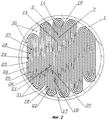
- на фиг.2 показано объединение стенок в число рядов более двух.The essence of the proposed heat exchanger is illustrated by drawings, where
- figure 1 shows the union of the walls in two rows,
- figure 2 shows the union of the walls in the number of rows of more than two.
В пространстве, охваченном корпусом 1 (фиг.1), расположены теплообменные элементы, состоящие из множества стенок. Каждая стенка, например 2, соединена с одного края 3 со смежной стенкой 4, а с другого края 5 - со стенкой 6, расположенной от нее через четное число промежуточных стенок 7 и 8, образуя ряды объединенных стенок 9, 10, канал 11 между рядами и каналы 12, 13 между рядами и корпусом 1. In the space covered by the housing 1 (FIG. 1), heat-exchange elements consisting of a plurality of walls are located. Each wall, for example 2, is connected from one edge 3 to an adjacent wall 4, and from the other edge 5 to a wall 6 located from it through an even number of
На фиг. 2 стенка 2 соединена со следующей стенкой аналогично описанному для фиг 1. Стенка, например 14, соединена с одного края 15 со стенкой 16, расположенной от нее через четное число промежуточных стенок 2 и 7, с другого края 17 - со следующей стенкой 18, расположенной от нее через четное число промежуточных стенок 19, 20, 21, 22, образуя ряды объединенных стенок 23, 24, 25, 26, каналы 27, 28, 29 между рядами и каналы 30, 31 между рядами и корпусом 1. In FIG. 2,
Работу теплообменника рассмотрим на примере, изображенном на фиг 1. We consider the operation of the heat exchanger using the example shown in FIG. 1.
Теплоноситель, например, нагреваемый газ, поступает в каналы 11 с одного торца теплообменника, продвигается вдоль по нему, нагревается, достигает выхода из канала с другого торца и выходит из теплообменника, при этом воздействие от давления нагреваемой среды через стенки 9, 10 воспринимается корпусом 1. Другой теплоноситель, например греющий газ, подается в каналы 12 и 13 навстречу нагреваемому, продвигается вдоль по ним, отдавая через стенки 9, 10 тепло нагреваемому газу, движущемуся в канале 11, и выходит из него
Предлагаемый теплообменник позволяет получить в том же объеме большую производительность, так как обеспечена более плотная компоновка, то есть более рационально использовано внутрикорпусное пространство, уменьшить гидравлическое сопротивление.A heat carrier, for example, a heated gas, enters the channels 11 from one end of the heat exchanger, moves along it, heats up, reaches the exit from the channel from the other end, and exits the heat exchanger, while the pressure from the heated medium through the walls 9, 10 is perceived by the housing 1 Another heat carrier, for example, heating gas, is supplied to the channels 12 and 13 towards the heated one, moves along them, giving heat through the walls 9, 10 to the heated gas moving in the channel 11, and leaves it
The proposed heat exchanger makes it possible to obtain greater productivity in the same volume, since a denser arrangement is provided, that is, the internal space is more rationally used, and hydraulic resistance is reduced.
Claims (1)
Priority Applications (1)
| Application Number | Priority Date | Filing Date | Title |
|---|---|---|---|
| RU2000109759A RU2188373C2 (en) | 2000-04-17 | 2000-04-17 | Heat exchanger |
Applications Claiming Priority (1)
| Application Number | Priority Date | Filing Date | Title |
|---|---|---|---|
| RU2000109759A RU2188373C2 (en) | 2000-04-17 | 2000-04-17 | Heat exchanger |
Publications (2)
| Publication Number | Publication Date |
|---|---|
| RU2000109759A RU2000109759A (en) | 2002-02-20 |
| RU2188373C2 true RU2188373C2 (en) | 2002-08-27 |
Family
ID=20233535
Family Applications (1)
| Application Number | Title | Priority Date | Filing Date |
|---|---|---|---|
| RU2000109759A RU2188373C2 (en) | 2000-04-17 | 2000-04-17 | Heat exchanger |
Country Status (1)
| Country | Link |
|---|---|
| RU (1) | RU2188373C2 (en) |
Cited By (1)
| Publication number | Priority date | Publication date | Assignee | Title |
|---|---|---|---|---|
| MD715Z (en) * | 2012-05-03 | 2014-07-31 | Институт Прикладной Физики Академии Наук Молдовы | Convective heat exchanger |
Citations (3)
| Publication number | Priority date | Publication date | Assignee | Title |
|---|---|---|---|---|
| US4330035A (en) * | 1979-09-04 | 1982-05-18 | Ab Ctc | Heat exchanger |
| SU1673820A1 (en) * | 1989-04-18 | 1991-08-30 | Азербайджанский Институт Нефти И Химии Им.М.Азизбекова | Double-pipe heat exchanger |
| RU2117892C1 (en) * | 1995-07-01 | 1998-08-20 | БДАГ Балке-Дюрр АГ | Heat exchanger |
-
2000
- 2000-04-17 RU RU2000109759A patent/RU2188373C2/en not_active IP Right Cessation
Patent Citations (3)
| Publication number | Priority date | Publication date | Assignee | Title |
|---|---|---|---|---|
| US4330035A (en) * | 1979-09-04 | 1982-05-18 | Ab Ctc | Heat exchanger |
| SU1673820A1 (en) * | 1989-04-18 | 1991-08-30 | Азербайджанский Институт Нефти И Химии Им.М.Азизбекова | Double-pipe heat exchanger |
| RU2117892C1 (en) * | 1995-07-01 | 1998-08-20 | БДАГ Балке-Дюрр АГ | Heat exchanger |
Non-Patent Citations (2)
| Title |
|---|
| БАРАНОВСКИЙ Н.В. и др. Пластинчатые и спиральные теплообменники. - М.: Машиностроение, 1973, с. 45-46. * |
| Справочник по теплообменникам/Под ред. О.Г. Мартыненко. - М.: ЭНЕРГОАТОМИЗДАТ, 1987, т. 2, с. 282-286. * |
Cited By (1)
| Publication number | Priority date | Publication date | Assignee | Title |
|---|---|---|---|---|
| MD715Z (en) * | 2012-05-03 | 2014-07-31 | Институт Прикладной Физики Академии Наук Молдовы | Convective heat exchanger |
Similar Documents
| Publication | Publication Date | Title |
|---|---|---|
| RU2099663C1 (en) | Heat exchanger | |
| US4883117A (en) | Swirl flow heat exchanger with reverse spiral configuration | |
| CN107664444B (en) | Side-process plate and shell heat exchanger plates and multi-process removable plate and shell heat exchangers | |
| RU2486425C1 (en) | Heat exchange unit | |
| US4002201A (en) | Multiple fluid stacked plate heat exchanger | |
| EP2569585B1 (en) | Device for compressing and drying gas | |
| JP5194010B2 (en) | Plate stack heat exchanger | |
| US5727118A (en) | Electric boiler for heat-transfer liquid circulating in an open or closed circuit | |
| CN205980877U (en) | Side flow plate-shell type heat exchange plate and multi-flow detachable plate-shell type heat exchanger | |
| US2730337A (en) | Heat exchanger | |
| US6470963B2 (en) | Heat exchanger | |
| US4989670A (en) | Heat exchanger | |
| US3525391A (en) | Heat exchanger and method of making same | |
| US20110114086A1 (en) | Heating device | |
| US2528013A (en) | Plate type heat exchanger | |
| US2081678A (en) | Heat exchanger | |
| RU2188373C2 (en) | Heat exchanger | |
| US3311166A (en) | Heat exchanger | |
| RU2042911C1 (en) | Plate heat exchanger | |
| US5121792A (en) | Countercurrent heat-exchanger | |
| US5797446A (en) | Plate heat exchanger | |
| RU2094726C1 (en) | Plate-type heat exchanger | |
| KR102723560B1 (en) | Integrated heat exchanger for vehicles | |
| RU2013737C1 (en) | Heat exchanger | |
| US821518A (en) | Regenerator or heat-exchanging apparatus. |
Legal Events
| Date | Code | Title | Description |
|---|---|---|---|
| MM4A | The patent is invalid due to non-payment of fees |
Effective date: 20070418 |