RU2187181C2 - Lamp-holder - Google Patents
Lamp-holder Download PDFInfo
- Publication number
- RU2187181C2 RU2187181C2 RU2000114904/09A RU2000114904A RU2187181C2 RU 2187181 C2 RU2187181 C2 RU 2187181C2 RU 2000114904/09 A RU2000114904/09 A RU 2000114904/09A RU 2000114904 A RU2000114904 A RU 2000114904A RU 2187181 C2 RU2187181 C2 RU 2187181C2
- Authority
- RU
- Russia
- Prior art keywords
- sleeve
- holder
- coupling
- lamp
- cartridge
- Prior art date
Links
Images


Abstract
Description
Область применения
Изобретение относится к светотехнике, а точнее к байонетным и винтовым патронам к лампам накаливания типа ДС (миньон), предназначенных для общего, местного и наружного освещения в быту в энергетических сетях напряжением 220В частотой 50 Гц. В соответствии с ГОСТ 12.2.007.13-88.Application area
The invention relates to lighting engineering, and more specifically to bayonet and screw cartridges for incandescent lamps of the type DS (minion), designed for general, local and outdoor lighting in everyday life in power networks with voltage of 220V and frequency of 50 Hz. In accordance with GOST 12.2.007.13-88.
К патронам для ламп с байонентным и винтовым цоколем предъявляются следующие требования:
1. Электрические требования, заключающиеся в обеспечении надежного контактного нажатия и связанной с ним электропроводностью на контактах.The lampholders for lamps with bayonet and screw cap have the following requirements:
1. Electrical requirements, which are to ensure reliable contact pressing and the associated conductivity at the contacts.
2. Механические требования, заключающиеся в механической прочности изделия, его стойкости к вибрации и тряске в заданном диапазоне частот и ударных нагрузок. Патроны, работающие в условиях повышенной вибрации и тряски, должны выдерживать следующие вибрационные и ударные нагрузки: диапазон частот от 1 до 100 Гц с ускорением 1 м/с2 и одиночные удары с ускорением 3 м/с2 длительностью от 40 до 60 мс.2. Mechanical requirements, consisting in the mechanical strength of the product, its resistance to vibration and shaking in a given range of frequencies and shock loads. Cartridges operating in conditions of increased vibration and shaking must withstand the following vibration and shock loads: the frequency range from 1 to 100 Hz with an acceleration of 1 m / s 2 and single impacts with an acceleration of 3 m / s 2 lasting from 40 to 60 ms.
3. Конструктивно-технологические требования заключаются в возможности изготовлять патроны наиболее простыми методами (штамповка, прессование, высадки и т. д.), а также минимальную трудоемкость при изготовлении и обеспечения высокого качества без применения индивидуальной регулировки. 3. The design and technological requirements consist in the ability to produce cartridges by the simplest methods (stamping, pressing, heading, etc.), as well as the minimum laboriousness in manufacturing and ensuring high quality without the use of individual adjustments.
4. Эксплуатационные требования, заключающиеся в удобстве монтажа, демонтажа, визуального контроля и регулировки. 4. Operational requirements, consisting in ease of installation, dismantling, visual inspection and adjustment.
В качестве аналогов заявляемому изобретению взята информация, приведенная в "Справочной книге по светотехнике", с.150-156, под редакцией Ю. Б. Айзенберга, М., Энергоатомиздат, 1983 г., книге Э.С. Розенталь "Электроустановочные устройства", с.5-18, М., Энергоатомиздат, 1987 г., каталоге электротехнической продукции "АО "Минимакс" 1999 г. As analogues of the claimed invention, the information is given in the "Reference book on lighting engineering", p.150-156, edited by Yu. B. Aisenberg, M., Energoatomizdat, 1983, the book by E.S. Rosenthal "Electrical Installation Devices", p.5-18, M., Energoatomizdat, 1987, catalog of electrical products "JSC" Minimaks "1999
В качестве прототипа взята нормативно-техническая документация: ГОСТ 361-78 "Патроны байонетные для электрических ламп накаливания. Технические условия". (Отменен и заменен на ГОСТ 9806-90 ГОСТ 2746-90 (МЭК 238-87), М., Издательство стандартов, 1991 г.(5)
Недостатками приведенных выше технических решений являются сложность в конструктивно-технологическом исполнении, а также отсутствие возможности визуального контроля надежности электорконтактов, ибо в патроне все скрыто конструктивно.The standard technical documentation is taken as a prototype: GOST 361-78 "Bayonet cartridges for electric incandescent lamps. Technical conditions". (Canceled and replaced by GOST 9806-90 GOST 2746-90 (IEC 238-87), M., Publishing house of standards, 1991 (5)
The disadvantages of the above technical solutions are the complexity in the structural and technological design, as well as the lack of the ability to visually control the reliability of electrical contacts, because everything is hidden constructively in the cartridge.
Известные конструкции патронов предназначены только для одного определенного цоколя - винтового типа. В 15/18, В 15/17, и В 15/19 по ГОСТ 17100-79. Known cartridge designs are intended for only one specific cap - screw type. B 15/18, B 15/17, and B 15/19 according to GOST 17100-79.
Патрона для включения ламп накаливания со штифтовым цоколем по ГОСТ 17100-79 (6) в промышленности нет, что создает определенные неудобства в технике изготовления и эксплуатации. There is no cartridge for turning on incandescent lamps with a pin base according to GOST 17100-79 (6) in the industry, which creates certain inconveniences in the manufacturing and operating techniques.
Описание заявленного изобретения
Заявляемое изобретение направлено на создание электропатрона для ламп накаливания в упрощенном конструктивно-технологическом исполнении, монтаже и надежном в эксплуатации как для ламп со штифтовым цоколем, так и для ламп с винтовым цоколем как бы в едином исполнении.Description of the claimed invention
The claimed invention is directed to the creation of an electric cartridge for incandescent lamps in a simplified structural and technological design, installation and reliable in operation for both lamps with a pin base and lamps with a screw base as if in a single design.
Патрон в предполагаемом изобретении можно назвать унифицированным на том основании, что оба как с винтовым цоколем, так и со штифтовым состоят из двух основных частей: муфты с токопроводящими элементами и гильзы. The cartridge in the proposed invention can be called unified on the basis that both with a screw base and a pin consist of two main parts: couplings with conductive elements and sleeves.
Гильза при этом, по существу и назначению является чехлом токопроводящих элементов муфты. The sleeve in this case, essentially the purpose is a cover of conductive elements of the coupling.
Конструктивно и в размерах гильза остается неизменной для обоих типов патронов, как для с винтовым, так и для штифтовым цоколем. Structurally and in size, the sleeve remains unchanged for both types of cartridges, both with screw and pin base.
Особо важно отметить муфта - как особо важный основной несущий комплекс электропередачи патрона, при определенных условиях безопасности (например, патрон устанавливается где-то в корпусе прибора, куда проникает специалист при обесточивании, иначе будет удар или короткое замыкание) может устанавливаться без гильзы. It is especially important to note the coupling - as a particularly important main load-bearing complex of the cartridge’s power transmission, under certain safety conditions (for example, the cartridge is installed somewhere in the device’s body, where the specialist penetrates when the power is off, otherwise there will be a shock or short circuit) can be installed without a sleeve.
Гильза служит чехлом токопроводящих элементов муфты патрона и насаживается на готовую, собранную к включению в эксплуатацию муфту, со стороны токопроводящих проводов. The sleeve serves as a cover for the conductive elements of the cartridge coupling and is mounted on the finished, assembled for commissioning of the coupling, from the side of the conductive wires.
Более подробно указанное техническое решение электропатрона поясняется фиг. 1-7. In more detail, the indicated technical solution of the electron cartridge is illustrated in FIG. 1-7.
На фиг.1 представлен заявляемый унифицированный электропатрон для электроламп "Миньон" со штифтовым цоколем, у которых оба электроконтакта лампочки выведены на торец цоколя. Figure 1 presents the inventive unified electric cartridge for electric lamps "Mignon" with a pin base, in which both the electrical contacts of the bulb are displayed on the end of the base.
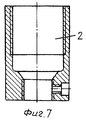
Здесь заявляемый патрон со штифтовым соединением (фиг.1) состоит из двух основных частей: муфты 1 с токопроводящими элементами и гильзы 2. Лампочка своими штифтами 4, скользя по канавке, погружается в муфту 1 до упора с лепестками 3, затем поворачивается на четверть оборота, скользя штифтами 4 уже по канавке 6 до упора. При этом пружинящиеся лепестки 3 обеспечивают надежный контакт электропередачи. Here, the inventive cartridge with a pin connection (Fig. 1) consists of two main parts: a
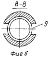
Муфта 1 имеет широкие два паза 9 (фиг.5 разрез Б-Б и фиг.6 разрез В-В). The
Благодаря пазам 9 в полой муфте образуется окно 10 (фиг.3), через которое можно визуально контролировать контактирование токопроводящих элементов. Thanks to the
Сборка патрона заканчивается навинчиванием гильзы (до упора) на муфту 1 со стороны токопроводящих проводов как для одного, так и для другого типа патронов. The cartridge assembly ends by screwing the sleeve (all the way) onto the
Патрон в собранном виде для ламп со штифтовым цоколем представлен на фиг.1. The assembled cartridge for lamps with a pin base is shown in figure 1.
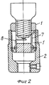
Патрон в собранном виде для ламп с винтовым цоколем представлен на фиг. 2. В этом случае вместо канавкам 5 и 6 (фиг.1) в муфте 1 (фиг.2) наносится резьба согласно шагу и профилю резьбы цоколя лампочки. В этом и есть единственное различие в муфтах патрона со штифтовым и винтовым соединением. An assembled cartridge for lamps with a screw cap is shown in FIG. 2. In this case, instead of the
Любой из существующих патронов состоит из трех-четырех основных частей: муфты, гильзы и соединительных частей муфты с гильзой. Any of the existing cartridges consists of three to four main parts: the coupling, the sleeve and the connecting parts of the coupling with the sleeve.
В прототипе проверка надежности сборки и контактирования с цоколем лампы визуально невозможна, так как все закрыто конструктивно. In the prototype, verification of the reliability of assembly and contact with the lamp base is visually impossible, since everything is structurally closed.
Проверка контактирования в прототипе возможна только функционально - включением в источник питания полностью собранного патрона с лампочкой. Checking the contact in the prototype is possible only functionally - by including in the power source a fully assembled cartridge with a bulb.
В заявленном унифицированном патроне надежность сборки и контактирования токопроводящих элементов проверяется и визуально через окно 10, так как гильза, служащая чехлом для токопроводящих элементов муфты, навинчивается на уже окончательно собранную визуально и физически проверенную, готовую к эксплуатации муфту (фиг.1,2 ). In the claimed unified cartridge, the reliability of the assembly and contacting of the conductive elements is checked visually through the
Необходимо отметить, что в условиях безопасного контактирования с окружающей средой муфта может применяться без гильзы, т.е. служить самостоятельно как патрон. It should be noted that in conditions of safe contact with the environment, the coupling can be used without a sleeve, i.e. serve independently as a cartridge.
Из вышеизложенного видно большое преимущество заявляемого патрона в изготовлении, эксплуатации и надежности его и насколько актуально для промышленности заявляемое изобретение. From the above shows the great advantage of the claimed cartridge in the manufacture, operation and reliability of it and how relevant for the industry the claimed invention.
Claims (1)
Priority Applications (1)
| Application Number | Priority Date | Filing Date | Title |
|---|---|---|---|
| RU2000114904/09A RU2187181C2 (en) | 2000-06-05 | 2000-06-05 | Lamp-holder |
Applications Claiming Priority (1)
| Application Number | Priority Date | Filing Date | Title |
|---|---|---|---|
| RU2000114904/09A RU2187181C2 (en) | 2000-06-05 | 2000-06-05 | Lamp-holder |
Publications (2)
| Publication Number | Publication Date |
|---|---|
| RU2187181C2 true RU2187181C2 (en) | 2002-08-10 |
| RU2000114904A RU2000114904A (en) | 2002-08-20 |
Family
ID=20235963
Family Applications (1)
| Application Number | Title | Priority Date | Filing Date |
|---|---|---|---|
| RU2000114904/09A RU2187181C2 (en) | 2000-06-05 | 2000-06-05 | Lamp-holder |
Country Status (1)
| Country | Link |
|---|---|
| RU (1) | RU2187181C2 (en) |
Cited By (3)
| Publication number | Priority date | Publication date | Assignee | Title |
|---|---|---|---|---|
| RU2489766C1 (en) * | 2012-04-06 | 2013-08-10 | Юлия Алексеевна Щепочкина | Light-emitting diode lamp base |
| RU2489767C1 (en) * | 2012-04-06 | 2013-08-10 | Юлия Алексеевна Щепочкина | Electric bulb base |
| RU2513147C2 (en) * | 2008-02-29 | 2014-04-20 | Конинклейке Филипс Электроникс Н.В. | Lamp base and method of its production |
-
2000
- 2000-06-05 RU RU2000114904/09A patent/RU2187181C2/en not_active IP Right Cessation
Cited By (3)
| Publication number | Priority date | Publication date | Assignee | Title |
|---|---|---|---|---|
| RU2513147C2 (en) * | 2008-02-29 | 2014-04-20 | Конинклейке Филипс Электроникс Н.В. | Lamp base and method of its production |
| RU2489766C1 (en) * | 2012-04-06 | 2013-08-10 | Юлия Алексеевна Щепочкина | Light-emitting diode lamp base |
| RU2489767C1 (en) * | 2012-04-06 | 2013-08-10 | Юлия Алексеевна Щепочкина | Electric bulb base |
Similar Documents
| Publication | Publication Date | Title |
|---|---|---|
| US4581687A (en) | Lighting means for illuminative or decorative purpose and modular lighting tube used therefor | |
| US4943900A (en) | Lighting fixture | |
| US7172332B2 (en) | Field bendable line voltage track lighting system | |
| US4495443A (en) | Compact fluorescent lamp combination, and method of making it | |
| US7784993B2 (en) | Watertight LED lamp | |
| JP2016532272A (en) | Light bulb assembly | |
| JP2016532271A (en) | Light bulb assembly | |
| US4405877A (en) | Variably positional lamp holder assembly | |
| ATE359611T1 (en) | ROTORLESS SOCKET FOR FLUORESCENT LAMPS | |
| RU2187181C2 (en) | Lamp-holder | |
| ES260608U (en) | Structure of fixing of the conductors for plugs and electric plugs (Machine-translation by Google Translate, not legally binding) | |
| US6905225B2 (en) | Floodlight and spotlight adapter and enclosure | |
| CA2199365A1 (en) | Current supply device for low voltage equipment | |
| GB2203001A (en) | Improved connection and fixing system for electronic unit | |
| US9006963B1 (en) | Light bulb with dual connectors | |
| US3882450A (en) | Lamp | |
| JP5455951B2 (en) | Lamp and lighting device using the lamp | |
| CN206036886U (en) | Car light and install vehicle of this car light | |
| CN104515015B (en) | A kind of LED | |
| CN218770163U (en) | Electric connector and lighting device | |
| US3456104A (en) | Lighting fixture having a lamp socket with insulation piercing means | |
| KR910001086B1 (en) | Indicator light | |
| CN214468438U (en) | Lamp fitting | |
| CN220321089U (en) | Quick concatenation line lamp suitable for high pressure fire prevention | |
| CN211176671U (en) | Lamp set |
Legal Events
| Date | Code | Title | Description |
|---|---|---|---|
| MM4A | The patent is invalid due to non-payment of fees |
Effective date: 20050606 |