RU2185550C2 - Flexible-and-torsional vibration damper - Google Patents
Flexible-and-torsional vibration damper Download PDFInfo
- Publication number
- RU2185550C2 RU2185550C2 RU94045420A RU94045420A RU2185550C2 RU 2185550 C2 RU2185550 C2 RU 2185550C2 RU 94045420 A RU94045420 A RU 94045420A RU 94045420 A RU94045420 A RU 94045420A RU 2185550 C2 RU2185550 C2 RU 2185550C2
- Authority
- RU
- Russia
- Prior art keywords
- hub
- ring
- mass
- shelf
- inertial mass
- Prior art date
Links
Images


Landscapes
- Vibration Prevention Devices (AREA)
- Vibration Dampers (AREA)
Abstract
Description
Изобретение относится к машиностроению, в частности двигателестроению, к усовершенствованию гасителей крутильно-изгибных колебаний двигателей внутреннего сгорания (ДВС). The invention relates to mechanical engineering, in particular engine manufacturing, to the improvement of dampers of torsional-bending vibrations of internal combustion engines (ICE).
Известен гаситель крутильно-изгибных колебаний, содержащий ступицу, кольцевую маховую инерционную массу и упругие элемента. (US, патент 4044627, кл. F 16 F 15/10, 1977). Known damper torsional-bending vibrations containing a hub, an annular flywheel inertial mass and elastic elements. (US patent 4044627, class F 16 F 15/10, 1977).
Недостатками известного гасителя являются невысокая способность гашения колебаний и долговечность. The disadvantages of the known damper are the low damping capacity and durability.
Техническим результатом данного изобретения являются повышение способности гашения колебаний, долговечности и обеспечение возможности изменения характеристик гасителя без его демонтажа с объекта. The technical result of this invention is to increase the ability to damp vibrations, durability and the ability to change the characteristics of the damper without removing it from the object.
Указанный технический результат достигается тем, что в известном гасителе крутильно-изгибных колебаний, содержащем ступицу, кольцевую маховую инерционную массу и упругие элементы, ступица выполнена в виде кольца Т-образной формы в поперечном сечении, первая полка которого расположена вдоль его оси, а вторая - радиально с внутренней стороны, кольцевая маховая инерционная масса выполнена составной в виде постоянной инерционной массы Т-образной формы в поперечном сечении, первая полка которой расположена вдоль ее оси, а вторая - радиально с наружной стороны, и дополнительной изменяемой массы, выполненной в виде набора сменных пластин различной толщины прямоугольного поперечного сечения, имеющих форму кольца или сегмента кольца, прикрепленных с двух сторон ко второй полке инерционной массы, каждый упругий элемент выполнен в виде пакета пластинчатых пружин, образующих цилиндр, при этом гаситель снабжен крепежными средствами, выполненными в виде крепежных болтов и цилиндрических сегментов, расположенных параллельно и симметрично друг к другу в цилиндре пакета пластинчатых пружин с возможностью поджатия пакета пластинчатых пружин с одной стороны к первой полке ступицы, а с другой стороны - к первой полке постоянной инерционной массы, причем по краям цилиндрических сегментов крепежных средств в плоскости их симметрии перпендикулярно их плоской поверхности на расстоянии, равном ширине пакета пластинчатых пружин, выполнены резьбовые отверстия, в которых установлены крепежные болты, расположенные на первых полках ступицы и кольцевой маховой инерционной массы. The specified technical result is achieved by the fact that in the known damper of torsional-bending vibrations containing a hub, an annular flywheel mass of inertia and elastic elements, the hub is made in the form of a T-shaped ring in cross section, the first shelf of which is located along its axis, and the second is radially from the inside, the annular flywheel mass of inertia is made composite in the form of a constant inertial mass of a T-shaped in cross section, the first shelf of which is located along its axis, and the second is radially the outer side, and an additional variable mass, made in the form of a set of interchangeable plates of different thicknesses of rectangular cross-section, having the shape of a ring or ring segment, attached on both sides to the second shelf of the inertial mass, each elastic element is made in the form of a package of leaf springs forming a cylinder, while the damper is equipped with fixing means made in the form of fixing bolts and cylindrical segments arranged parallel and symmetrically to each other in the cylinder of the plate x springs with the possibility of preloading the package of leaf springs on one side to the first shelf of the hub, and on the other hand to the first shelf of constant inertial mass, and along the edges of the cylindrical segments of the fastening means in the plane of their symmetry perpendicular to their flat surface at a distance equal to the width of the plate pack springs, threaded holes are made in which mounting bolts are installed, located on the first shelves of the hub and ring flywheel mass.
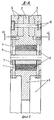
На фиг.1 изображен общий вид гасителя; на фиг.2 - сечение А-А на фиг.1; на фиг.3 изображен упругий элемент в виде пакета пластинчатых пружин, образующих цилиндр, с цилиндрическими сегментами; на фиг.4 изображена схема гасителя с примерами выполнения дополнительных элементов к крепежным средствам пакета пластинчатых пружин. Figure 1 shows a General view of the damper; figure 2 is a section aa in figure 1; figure 3 shows the elastic element in the form of a package of leaf springs forming a cylinder with cylindrical segments; figure 4 shows a diagram of a damper with examples of additional elements to the fastening means of a package of leaf springs.
Гаситель содержит ступицу 1, выполненную в виде кольца Т-образной формы в поперечном сечении, первая полка которого расположена вдоль его оси, а вторая - радиально с внутренней стороны, кольцевую маховую инерционную массу, выполненную составной в виде постоянной инерционной массы 2 Т-образной формы в поперечном сечении, первая полка которой расположена вдоль ее оси, а вторая - радиально с наружной стороны, и дополнительной изменяемой массы 3, выполненной в виде набора сменных пластин различной толщины прямоугольного поперечного сечения, имеющих форму кольца или сегмента кольца, прикрепленных с двух сторон ко второй полке постоянной инерционной массы, упругие демпфирующие элементы 4 и крепежные средства. Каждый упругий демпфирующий элемент 4 выполнен в виде пакета пластинчатых пружин, образующих цилиндр. Крепежные средства выполнены в виде болтов 5, 6 и цилиндрических сегментов 7, 8, которые цилиндрическими поверхностями В, С расположены параллельно и симметрично друг другу по длине "L" в цилиндре "Д" пакета пластинчатых пружин с возможностью поджатия пакета пластинчатых пружин с одной стороны к первой полке ступицы I, а с другой стороны - к первой полке постоянной инерционной массе 2. Причем по краям цилиндрических сегментов 5, 6 крепежных средств в плоскости их симметрии перпендикулярно их плоской поверхности на расстоянии "L0", равном ширине пакета пластинчатых пружин, выполнены резьбовые отверстия E, F диаметром d, в которых установлены крепежные болты 5, 6, расположенные на первых полках ступицы и постоянной инерционной массы. Кроме того, крепежные средства могут быть выполнены также с дополнительными элементами в виде колец 9, 10, рычагов 11, 12, пластин 13, 14 и болтов, винтов и шпилек 15, 18.The absorber contains a
Гаситель работает следующем образом. The damper works as follows.
При возникновении на валу объекта порциальных крутильных или изгибных колебаний, а также попарных (связанных) крутильно-изгибных колебаний кольцевая маховая инерционная масса под действием сил инерции совершает колебательные движения, которые передаются упругим демпфирующим элементам 4, где за счет упругой деформации и трения цилиндрических пластинчатых пружин происходит гашение этих колебаний. При этом сами упругие демпфирующие элементы 4 деформируются, как от сил кручения, так и от растягивающих сил и сил сжатия, приобретая форму эллипса. In case of occurrence of partial torsional or bending vibrations on the object’s shaft, as well as pairwise (coupled) torsional-bending vibrations, the ring flywheel mass under the action of inertia forces oscillates, which are transmitted to the
Конструкция узла крепления каждого упругого демпфирующего элемента 4 между ступицей 1 и постоянной инерционной массой 2 позволяет обеспечить регулировку упруго-демпфирующей характеристики гасителя за счет изменения усилия поджатия болтами 5, 6 каждого упругого элемента 4 с одной стороны к ступице I, а с другой - к постоянной инерционной массе 2. The design of the attachment point of each
При этом предпочтительно обеспечить такое поджатие упругих демпфирующих элементов 4 болтами 5, 6, чтобы при колебаниях произошло свободное трение (проскальзывание) пакета пластинчатых пружин по всему периметру, в том числе в местах зажима (контакта) с цилиндрическими сегментами 7, 8 и соответствующих точках ступицы 1 и постоянной инерционной массы 2. In this case, it is preferable to ensure that the
Для возможности такой регулировки непосредственно в условиях эксплуатации дополнительные изменяемые массы 3 установлены с внутренним диаметром с зазором Δ относительно головки болтов 6. To enable such adjustment directly under operating conditions, additional
Указанные особенности работы упругих демпфирующих элементов, кроме обеспечения высокой эффективности, способствуют также увеличению срока службы гасителя в целом. These features of the elastic damping elements, in addition to ensuring high efficiency, also contribute to an increase in the life of the damper as a whole.
Claims (1)
Priority Applications (1)
| Application Number | Priority Date | Filing Date | Title |
|---|---|---|---|
| RU94045420A RU2185550C2 (en) | 1994-12-27 | 1994-12-27 | Flexible-and-torsional vibration damper |
Applications Claiming Priority (1)
| Application Number | Priority Date | Filing Date | Title |
|---|---|---|---|
| RU94045420A RU2185550C2 (en) | 1994-12-27 | 1994-12-27 | Flexible-and-torsional vibration damper |
Publications (2)
| Publication Number | Publication Date |
|---|---|
| RU94045420A RU94045420A (en) | 1996-10-10 |
| RU2185550C2 true RU2185550C2 (en) | 2002-07-20 |
Family
ID=20163519
Family Applications (1)
| Application Number | Title | Priority Date | Filing Date |
|---|---|---|---|
| RU94045420A RU2185550C2 (en) | 1994-12-27 | 1994-12-27 | Flexible-and-torsional vibration damper |
Country Status (1)
| Country | Link |
|---|---|
| RU (1) | RU2185550C2 (en) |
Families Citing this family (1)
| Publication number | Priority date | Publication date | Assignee | Title |
|---|---|---|---|---|
| DE102018218812A1 (en) * | 2018-11-05 | 2020-05-07 | Zf Friedrichshafen Ag | Torsion damper for wind turbines |
-
1994
- 1994-12-27 RU RU94045420A patent/RU2185550C2/en active
Non-Patent Citations (1)
| Title |
|---|
| US, патент № 4044627, кл. F 16 F 15/10, 1997. * |
Also Published As
| Publication number | Publication date |
|---|---|
| RU94045420A (en) | 1996-10-10 |
Similar Documents
| Publication | Publication Date | Title |
|---|---|---|
| EP1307669B1 (en) | Dual ring damper | |
| US3670593A (en) | Series type vibration damper | |
| US3314304A (en) | Series compound torsional vibration damper | |
| US6854721B2 (en) | Vibration-damping device | |
| AU2001281333A1 (en) | Dual ring damper | |
| KR20140088095A (en) | Pendulum-oscillator-type damping system comprising an improved guiding device | |
| JP7181326B2 (en) | torsional vibration damper | |
| KR102575110B1 (en) | pendulum damping device | |
| US4083265A (en) | Torsional vibration damper | |
| JP3556056B2 (en) | Flexible plate and flywheel assembly using the same | |
| US4023438A (en) | Torsional vibration damper | |
| KR100390089B1 (en) | Flexible flywheel | |
| RU2185550C2 (en) | Flexible-and-torsional vibration damper | |
| RU162654U1 (en) | VIBRATION DAMPER FOR INTERNAL COMBUSTION ENGINE | |
| US3285096A (en) | Torsional vibration damper | |
| US3077123A (en) | Tuned friction damper | |
| US5533422A (en) | System for absorbing torsional and/or bending vibrations | |
| US20190011011A1 (en) | Vibration absorber for internal combustion engine | |
| KR20040082924A (en) | Torsional vibration damper | |
| JPH08177874A (en) | Torsional vibration damper integral type torsional elastic joint | |
| JPH11236928A (en) | Elastic clutch | |
| KR101836635B1 (en) | Apparatus for reducing vibration | |
| US20050022774A1 (en) | Torsional vibration damper | |
| RU123481U1 (en) | TORQUE OSCILLATOR | |
| SU934082A1 (en) | Torque oscillation damper |