RU2179503C2 - Abrasive annular embracing wheel - Google Patents
Abrasive annular embracing wheel Download PDFInfo
- Publication number
- RU2179503C2 RU2179503C2 RU99122549A RU99122549A RU2179503C2 RU 2179503 C2 RU2179503 C2 RU 2179503C2 RU 99122549 A RU99122549 A RU 99122549A RU 99122549 A RU99122549 A RU 99122549A RU 2179503 C2 RU2179503 C2 RU 2179503C2
- Authority
- RU
- Russia
- Prior art keywords
- abrasive
- screw
- circle
- housing
- processing
- Prior art date
Links
- 239000011248 coating agent Substances 0.000 abstract 1
- 238000000576 coating method Methods 0.000 abstract 1
- 239000000126 substance Substances 0.000 abstract 1
- 238000005520 cutting process Methods 0.000 description 7
- 238000003754 machining Methods 0.000 description 5
- 239000002184 metal Substances 0.000 description 3
- 238000000034 method Methods 0.000 description 3
- 238000004519 manufacturing process Methods 0.000 description 2
- 244000309464 bull Species 0.000 description 1
- 230000008859 change Effects 0.000 description 1
- 230000006835 compression Effects 0.000 description 1
- 238000007906 compression Methods 0.000 description 1
- 239000002826 coolant Substances 0.000 description 1
- 230000008878 coupling Effects 0.000 description 1
- 238000010168 coupling process Methods 0.000 description 1
- 238000005859 coupling reaction Methods 0.000 description 1
- 239000002173 cutting fluid Substances 0.000 description 1
- 238000010586 diagram Methods 0.000 description 1
- 230000008642 heat stress Effects 0.000 description 1
- 239000000463 material Substances 0.000 description 1
- 238000011089 mechanical engineering Methods 0.000 description 1
- 230000008569 process Effects 0.000 description 1
- 230000009467 reduction Effects 0.000 description 1
Images
Landscapes
- Polishing Bodies And Polishing Tools (AREA)
Abstract
Description
Изобретение относится к машиностроению, к области станкостроения, и может быть использовано при финишной абразивной обработке валов с переменным сечением, винтовых поверхностей точных винтов, например винтов винтовых насосов, из трудношлифуемых материалов методом охватывающего шлифования. The invention relates to mechanical engineering, to the field of machine tool engineering, and can be used for finishing abrasive machining of shafts with a variable cross section, screw surfaces of precision screws, for example screw pumps, from hard-to-grind materials using the method of covering grinding.
Известен шлифовальный круг, содержащий кольцеобразный корпус, выполненный в виде двух сегментов, соединенных замками. На корпусе закреплен абразивный слой [1]. Known grinding wheel containing an annular body made in the form of two segments connected by locks. An abrasive layer [1] is fixed on the body.
Недостатками этого шлифовального круга являются трудности изготовления сегментов корпуса малого сечения с приемлемым отклонением от плоскостности и круглости и трудность изготовления замков, прочно удерживающих сегменты, зазоры между сегментами, что приводит к вибрации при вращении круга. Кроме того, существенными недостатками круга являются ограниченность его применения, а именно только для обработки отверстий некруглой формы, и минимальная площадь контакта инструмента с заготовкой, не позволяющая интенсифицировать режимы обработки. The disadvantages of this grinding wheel are the difficulty of manufacturing segments of the housing of small cross section with an acceptable deviation from flatness and roundness and the difficulty of manufacturing locks that firmly hold the segments, the gaps between the segments, which leads to vibration during rotation of the wheel. In addition, significant disadvantages of the circle are its limited use, namely, only for processing non-circular holes, and the minimum contact area of the tool with the workpiece, which does not allow to intensify the processing modes.
Известен шлифовальный круг, выполненный в виде кольцеобразного корпуса с закрепленным на нем абразивным слоем, при этом корпус представляет собой цилиндрическую пружину сжатия и витки пружины снабжены элементом фиксации их в сомкнутом положении [2]. Known grinding wheel, made in the form of an annular body with an abrasive layer fixed on it, while the body is a cylindrical compression spring and the turns of the spring are equipped with an element for fixing them in the closed position [2].
Недостатками известного инструмента является ограниченность применения, а именно только для обработки отверстий некруглой формы, минимальная площадь контакта инструмента с заготовкой, не позволяющая интенсифицировать режимы обработки, и сложность реализации, требующая специального оборудования. The disadvantages of the known tool is the limited application, namely, only for processing holes of non-circular shape, the minimum contact area of the tool with the workpiece, which does not allow to intensify the processing modes, and the complexity of implementation, requiring special equipment.
Задачей изобретения является повышение качества, производительности и точности обработки винтов, например винтовых насосов, а также валов с переменным сечением за счет использования метода охватывающего шлифования, увеличивающий площадь контакта инструмента и заготовки и позволяющий интенсифицировать обработку винтовых поверхностей. The objective of the invention is to improve the quality, performance and accuracy of processing screws, such as screw pumps, and shafts with a variable cross-section through the use of the method of covering grinding, increasing the contact area of the tool and the workpiece and allowing to intensify the processing of screw surfaces.
Поставленная задача решается предлагаемым абразивным охватывающим кругом, состоящим из выполненного в виде цилиндрической пружины корпуса и закрепленного на нем абразивного слоя, при этом для обработки винтов он снабжен закрепленными на наружной поверхности корпуса кронштейнами с пазами, а абразивный слой закреплен на внутренней поверхности корпуса, при этом рабочая поверхность круга имеет профиль впадины обрабатываемого винта, а шаг цилиндрической пружины составляет половину шага обрабатываемого винта. The problem is solved by the proposed abrasive covering circle, consisting of a shell made in the form of a coil spring and an abrasive layer fixed on it, while for processing the screws it is equipped with brackets fixed on the outer surface of the housing, and the abrasive layer is fixed on the inner surface of the housing, while the working surface of the circle has a profile of the cavity of the machined screw, and the step of the coil spring is half the pitch of the machined screw.
Сущность предлагаемой конструкции круга поясняется чертежами. The essence of the proposed design of the circle is illustrated by drawings.
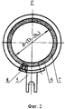
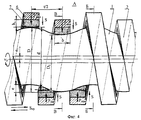
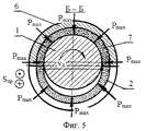
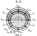
На фиг. 1 изображен абразивный кольцеобразный охватывающий круг, в свободном состоянии; на фиг. 2 - вид Г слева на фиг. 1; на фиг. 3 приведена схема обработки винта предлагаемым кругом; на фиг. 4 - элемент А на фиг. 3, частичный продольный разрез; на фиг. 5 - разрез по Б-Б на фиг. 4; на фиг. 6 - разрез по В-В на фиг. 4. In FIG. 1 shows an abrasive ring-shaped covering circle, in a free state; in FIG. 2 is a left view of FIG. 1; in FIG. 3 shows a diagram of the processing of the screw proposed circle; in FIG. 4 - element A in FIG. 3, a partial longitudinal section; in FIG. 5 is a section along BB in FIG. 4; in FIG. 6 is a section along BB in FIG. 4.
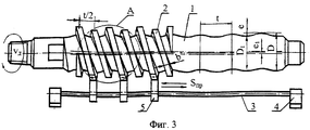
Для эффективной финишной абразивной обработки винтов 1 (например, винтовых насосов, имеющих профиль и размеры D, D1, t, е, e1, показанные на фиг. 3 и 4) предлагается абразивный кольцеобразный охватывающий круг 2.For effective finishing abrasive processing of screws 1 (for example, screw pumps having a profile and dimensions D, D 1 , t, e, e 1 shown in Figs. 3 and 4), an abrasive annular ring-
Круг 2, выполненный в виде цилиндрической пружины, одевают на обрабатываемую заготовку винта 1. При вращении заготовки 1 круг 2 затормаживают с помощью штанги 3, которая неподвижно на стойках 4 закреплена, например, на суппорте (не показан). Сопряжение круга 2 со штангой 3 производится с помощью кронштейнов 5, которые закреплены на витках круга 2, и охватывают штангу 3 благодаря пазам, имеющимся в нижней части кронштейнов 5.
Абразивный охватывающий [3] круг 2 состоит из корпуса 6, который представляет собой винтовую цилиндрическую пружину, сечение витка которой может иметь разнообразный профиль. Величина шага винтовой цилиндрической пружины влияет на интенсивность съема металла при обработке, кроме того, шаг винтовой цилиндрической пружины должен быть не более половины шага обрабатываемого винта. На внутреннюю кольцеобразную поверхность корпуса 6 нанесен абразивный слой 7, например, на гибкой вулканитовой или резиновой связке, или на корпусе 6 может быть закреплен проволочно-абразивный инструмент. Режущая абразивная рабочая поверхность заправлена по профилю впадины обрабатываемого винта. The abrasive covering [3]
Кронштейны 5 закреплены на наружной поверхности витков корпуса с помощью винтов 8 или другим известным способом. The
Винту 1 сообщают вращения вокруг своей оси со скоростью vд = vи, равной скорости инструмента при абразивной обработки. Скорость назначается согласно характеристики охватывающего абразивного круга и режущих свойств инструмента, как при обычной традиционной абразивной обработке.The
Одновременно с главным движением резания, которым является вращение заготовки, инструменту сообщают возвратно-поступательную продольную подачу с помощью упоров (не показаны), которые действуют на крайние кронштейны 5, или роль упоров могут выполнять стойки 4 при их возвратно-поступательном движении вдоль оси. Simultaneously with the main cutting movement, which is the rotation of the workpiece, the tool is informed of the reciprocating longitudinal feed with the help of stops (not shown), which act on the
Охватывая обрабатываемый винт 1 и благодаря пружинящим свойствам корпуса 6, витки абразивного круга, перемещаясь вдоль оси и копируя профиль винта, изменяют свои размеры в радиальном направлении (фиг. 5 и 6), обеспечивая радиальную подачу S. Витки увеличиваются и уменьшаются в диаметре, в поперечном сечении принимая форму круга (фиг. 6) или эллипса (фиг. 5), и внутренней рабочей поверхностью, в сечении имеющей профиль впадины винтовой поверхности обрабатываемого винта, ведут интенсивную абразивного обработку по всей длине винта, захватываемой инструментом. Covering the screw being machined 1 and due to the spring properties of the
Внутренняя абразивная рабочая поверхность витка круга, заправленная первоначально по форме впадины и поддерживающая этот профиль благодаря самозаточке, в процессе обработки занимает положение как во впадине, так и на выступе. При этом находясь, во впадине, виток круга контактирует с заготовкой всей режущей поверхностью, снимая максимум металла, находясь на выступе - по линии, снимая минимум. Но так как во впадине виток круга разжат в меньшей степени, то усилие радиальной подачи меньше и равно Рmin. На виток, находящийся на выступе, действует большее усилие радиальной подачи Рmax, поэтому съем металла на вершинах и впадинах обрабатываемого винта будет равномерный.The inner abrasive working surface of a circle coil, initially tucked in the shape of a cavity and supporting this profile due to self-sharpening, occupies a position both in the cavity and on the protrusion during processing. At the same time, while in the cavity, the circle turn contacts the workpiece with the entire cutting surface, removing the maximum metal, while on the protrusion - along the line, removing the minimum. But since in the cavity the circle is unclenched, the radial feed force is less and equal to P min . On the coil located on the protrusion, there is a greater force of the radial feed P max , so the removal of metal at the tops and troughs of the machined screw will be uniform.
Достоинствами обработки кольцевым кругом являются возможность абразивной обработки валов с переменным сечением, в частности винтов, легко достижима нужная скорость резания, высокая производительность. Advantages of machining with an annular circle are the possibility of abrasive machining of shafts with a variable cross-section, in particular of screws, the desired cutting speed and high productivity are easily achievable.
Преимущества кольцевых охватывающих абразивных кругов: отсутствие стыков; более плавное вращение; большая жесткость технологической системы, нет необходимости поддерживать от прогиба люнетом обрабатываемый нежесткий, имеющий большую длину при малом диаметре винт (как при традиционном круглом шлифовании); повышается качество и точность обработки, благодаря кольцевому схватыванию инструментом обрабатываемой поверхности при снятии больших неравномерных припусков; в 2-3 раза повышается производительность обработки благодаря большой площади контакта инструмента с заготовкой и сокращению количества проходов; свободный доступ смазочно-охлаждающей жидкости (СОЖ) в зону резания между витками также положительно влияет на производительность. Advantages of annular covering abrasive wheels: lack of joints; smoother rotation; high rigidity of the technological system; there is no need to support a machined non-rigid screw having a large length with a small diameter from the deflection of the rest (as with traditional round grinding); the quality and accuracy of processing are improved, thanks to the ring setting of the machined surface by the tool when removing large uneven allowances; processing productivity is increased by a factor of 2–3 due to the large contact area of the tool with the workpiece and the reduction in the number of passes; free access of cutting fluid (coolant) to the cutting zone between the turns also positively affects productivity.
Благодаря применению предлагаемого абразивного кольцеобразного охватывающего круга при обработки винтовых поверхностей винтов, например винтовых насосов, расширяются технологические возможности путем повышения жесткости инструмента, улучшается качество, повышается производительность за счет снижения теплонапряженности процесса и гарантируется бесприжоговая обработка. Thanks to the use of the proposed abrasive ring-shaped enclosing circle when machining screw surfaces of screws, for example screw pumps, technological capabilities are expanded by increasing the stiffness of the tool, quality is improved, productivity is improved by reducing the heat stress of the process and guaranteed mash-free processing.
Источники информации
1. А. с. СССР 184650, кл. В 24 D 5/06, 1965.Sources of information
1. A. p. USSR 184650, class B 24
2. А. с. СССР 960002, кл. В 24 D 5/00, заяв. 3004758/25-08, заявл. 17.11.80, опубл. 23.09.82. Бюл. 35 - прототип. 2. A. p. USSR 960002, class In 24
3. Казаков В. М. Шлифование при повышенных скоростях резания. -Киев: Технiка, 1971. С. 9-11. 3. Kazakov V. M. Grinding at high cutting speeds. -Kiev: Technics, 1971.P. 9-11.
Claims (1)
Priority Applications (1)
| Application Number | Priority Date | Filing Date | Title |
|---|---|---|---|
| RU99122549A RU2179503C2 (en) | 1999-10-27 | 1999-10-27 | Abrasive annular embracing wheel |
Applications Claiming Priority (1)
| Application Number | Priority Date | Filing Date | Title |
|---|---|---|---|
| RU99122549A RU2179503C2 (en) | 1999-10-27 | 1999-10-27 | Abrasive annular embracing wheel |
Publications (1)
| Publication Number | Publication Date |
|---|---|
| RU2179503C2 true RU2179503C2 (en) | 2002-02-20 |
Family
ID=20226259
Family Applications (1)
| Application Number | Title | Priority Date | Filing Date |
|---|---|---|---|
| RU99122549A RU2179503C2 (en) | 1999-10-27 | 1999-10-27 | Abrasive annular embracing wheel |
Country Status (1)
| Country | Link |
|---|---|
| RU (1) | RU2179503C2 (en) |
Citations (1)
| Publication number | Priority date | Publication date | Assignee | Title |
|---|---|---|---|---|
| SU960002A1 (en) * | 1980-11-17 | 1982-09-23 | Предприятие П/Я М-5893 | Grinding wheel |
-
1999
- 1999-10-27 RU RU99122549A patent/RU2179503C2/en active
Patent Citations (1)
| Publication number | Priority date | Publication date | Assignee | Title |
|---|---|---|---|---|
| SU960002A1 (en) * | 1980-11-17 | 1982-09-23 | Предприятие П/Я М-5893 | Grinding wheel |
Non-Patent Citations (1)
| Title |
|---|
| КАЗАКОВ В.Ф. Шлифование при повышенных скоростях резания. - Киев: Технiка, 1971, с.9-11, рис.1 * |
Similar Documents
| Publication | Publication Date | Title |
|---|---|---|
| JP3408823B2 (en) | External polishing machine | |
| KR100273663B1 (en) | Method for processing an axis for hub unit | |
| RU2179503C2 (en) | Abrasive annular embracing wheel | |
| RU2170650C1 (en) | Method for abrasive working of screws by means of annular embracing tool | |
| JP3408822B2 (en) | Internal polishing machine | |
| CN118284492A (en) | Honing tool and method for producing a honing tool | |
| JP2003175453A (en) | Honing tool | |
| JP2015066672A (en) | Ball screw manufacturing method and ball screw | |
| JP3265640B2 (en) | Super finishing method and swing mechanism for annular groove | |
| JP2002079469A (en) | Grinding wheel | |
| JP2018099762A (en) | Honing device | |
| RU2212987C1 (en) | Method for grinding and honing gear wheels | |
| RU2169644C2 (en) | Head for embracing type grinding of screws | |
| RU2228240C1 (en) | Apparatus for finishing screws | |
| RU2230648C1 (en) | Method for finishing screws with use of wire -abrasive embracing type tool | |
| RU2121422C1 (en) | Method of treatment of holes | |
| RU2176179C2 (en) | Method of grinding screws with unifilar grinding wheel | |
| US3031808A (en) | Apparatus for manufacturing bearing races and the like | |
| RU2165340C1 (en) | Method for grinding screws by means of multistrand grinding wheel | |
| RU2137582C1 (en) | Method of finishing treatment | |
| RU2237567C2 (en) | Method of grinding and polishing openings | |
| JP2004276172A (en) | Grinding method and method of manufacturing grinding wheel | |
| RU2236933C1 (en) | Device for grinding and honing | |
| RU2146599C1 (en) | Grinding wheel fastening device | |
| RU2204471C2 (en) | Method for abrasive working of grooves and other surfaces |