RU2178503C1 - Device for driving of horizontal and inclined workings - Google Patents
Device for driving of horizontal and inclined workings Download PDFInfo
- Publication number
- RU2178503C1 RU2178503C1 RU2000123660/03A RU2000123660A RU2178503C1 RU 2178503 C1 RU2178503 C1 RU 2178503C1 RU 2000123660/03 A RU2000123660/03 A RU 2000123660/03A RU 2000123660 A RU2000123660 A RU 2000123660A RU 2178503 C1 RU2178503 C1 RU 2178503C1
- Authority
- RU
- Russia
- Prior art keywords
- working
- housing
- flaps
- tubes
- wing
- Prior art date
Links
Images

Landscapes
- Earth Drilling (AREA)
Abstract
Description
Изобретение относится к горной промышленности и строительной индустрии и касается устройств для проходки горизонтальных и наклонных выработок различного назначения. The invention relates to the mining and construction industries and relates to devices for sinking horizontal and inclined workings for various purposes.
В данной области технологий в настоящее время известны принципиальные технические решения, наиболее представительным и наиболее близким из которых является устройство для проходки горизонтальных и наклонных выработок, содержащее бурильный агрегат в виде автономного бурильного аппарата, имеющего удлиненный корпус с размещенным в нем генератором рабочего тела, закрепленный на одном торце корпуса рабочий орган с соплами для истечения рабочего тела под давлением на забой в виде струй, средство управления положением корпуса бурильного аппарата при проходке выработки /SU 522759, 03.06.1977/. In this field of technology, fundamental technical solutions are currently known, the most representative and closest of which is a device for sinking horizontal and inclined workings, containing a drilling unit in the form of an autonomous drilling apparatus having an elongated body with a working fluid generator mounted on it one end of the body working body with nozzles for the expiration of the working fluid under pressure on the bottom in the form of jets, a means of controlling the position of the drill housing the device during the sinking / SU 522759, 06/03/1977 /.
Обладая определенными техническими преимуществами перед другими аналогами, это устройство имеет и ряд очевидных и существенных недостатков, заключающихся в отсутствии технических средств для оперативного изменения направления проходки выработки и невозможности выдерживать заданное направление проходки ввиду постоянно меняющихся условий в выработке. Эти существенные недостатки снижают тактико-технические характеристики известного бурильного аппарата. Possessing certain technical advantages over other analogues, this device also has a number of obvious and significant drawbacks, namely the lack of technical means for quickly changing the direction of excavation and the inability to withstand a given direction of excavation due to constantly changing conditions in the excavation. These significant disadvantages reduce the performance characteristics of the known drilling apparatus.
Технической задачей и результатом данного изобретения является повышение управляемости и тактико-технических характеристик устройства, повышение надежности и точности выдерживания заданных направлений проходки выработки. The technical task and the result of this invention is to increase the controllability and performance characteristics of the device, to increase the reliability and accuracy of maintaining the given directions of mine working.
Указанная задача и технический результат в изобретении достигаются за счет того, что устройство для проходки горизонтальных и наклонных выработок, содержащее бурильный агрегат в виде автономного бурильного аппарата, имеющего удлиненный корпус с размещенным в нем генератором рабочего тела, закрепленный на одном торце корпуса рабочий орган с соплами для истечения рабочего тела под давлением на забой в виде струй, средство управления положением корпуса бурильного аппарата при проходке выработки, средство управления положением корпуса аппарата при проходке выработки выполнено в виде нескольких аэродинамических приспособлений, часть из которых представляет собой консольные закрылки, закрепленные на приводных консольно установленных в стенках корпуса валах, другая часть выполнена в виде обтекаемого монокрыла, закрепленного одним концом со стороны рабочего органа на корпусе посредством шаровой опоры и имеющего привод его ориентирования по выбору угла атаки - положения вдоль корпуса, причем одна поверхность консольных закрылков и монокрыла выполнена криволинейной выпуклой, а другая - или вогнутой или прямолинейной, при этом в корпусе размещен узел отслеживания положения корпуса, выполненный в виде изогнутых трубок, заполненных нейтральной нетокопроводящей жидкостью, в среде которой размещены подвижные тела с электропроводящей оболочкой, торцы этих трубок герметизированы, а на стенках у торцов трубок закреплены пары токопроводящих контактных выводов, соединенных с программированным блоком управления, которым снабжено устройство. The specified task and the technical result in the invention are achieved due to the fact that the device for sinking horizontal and inclined workings, containing a drilling unit in the form of an autonomous drilling device having an elongated body with a working fluid generator mounted on it, a working body with nozzles mounted on one end of the body for the expiration of the working fluid under pressure on the bottom in the form of jets, a means of controlling the position of the housing of the drilling apparatus during excavation, a means of controlling the position of the housing a the apparatus during excavation is made in the form of several aerodynamic devices, some of which are cantilevered flaps mounted on the drive shafts mounted in the casing walls of the body, the other part is made in the form of a streamlined mono-wing, fixed at one end from the side of the working body on the body by means of a ball joint and having a drive of its orientation according to the choice of the angle of attack - the position along the hull, moreover, one surface of the cantilever flaps and the single wing is made curved bent and the other either concave or rectilinear; in this case, a housing position tracking unit is placed in the form of bent tubes filled with a neutral non-conductive liquid, in the environment of which moving bodies with an electrically conductive shell are placed, the ends of these tubes are sealed, and on the walls the ends of the tubes are fixed pairs of conductive contact leads connected to the programmed control unit, which is equipped with the device.
Описываемое устройство для проходки горизонтальных и наклонных выработок раскрывается далее на чертежах, где:
на фиг. 1 показан его общий вид по продольной оси;
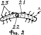
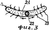
на фиг. 2 и фиг. 3 раскрыт узел "A" на фиг. 1;
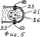
на фиг. 4 и фиг. 5 показаны детали узла "A" на фиг. 3 и фиг. 4;
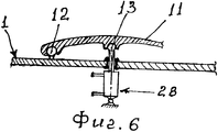
на фиг. 6 показан привод монокрыла устройства;
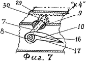
на фиг. 7 - деталь привода консольного закрылка;
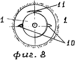
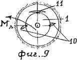
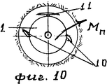
на фиг. 8, фиг. 9 и фиг. 10 - положение корпуса устройства при проходке выработки.The described device for driving horizontal and inclined workings is disclosed further in the drawings, where:
in FIG. 1 shows its general view along the longitudinal axis;
in FIG. 2 and FIG. 3, the assembly “A” in FIG. 1;
in FIG. 4 and FIG. 5 shows details of the assembly “A” in FIG. 3 and FIG. 4;
in FIG. 6 shows the mono-wing drive of the device;
in FIG. 7 - detail of the console flap drive;
in FIG. 8, FIG. 9 and FIG. 10 - position of the housing of the device when driving the mine.
Устройство для проходки горизонтальных и наклонных выработок в геологических структурах содержит бурильный агрегат, выполненный в виде автономного бурильного аппарата, имеющего удлиненный корпус 1 (фиг. 1), на одном торце корпуса закреплен породоразрушающий рабочий орган 2, а в полости корпуса размещен генератор 3 рабочего тела (генератор на чертеже не раскрыт, как не имеющий прямого отношения к изобретению). Устройство также снабжено программированным блоком 4 управления его работой и основными узлами, раскрытыми на чертежах. Рабочий орган 2 имеет сопла 5 для истечения рабочего тела на забой и сопла 6 для создания усилия подачи устройства к забою и организации восходящего потока бурового шлама. A device for driving horizontal and inclined workings in geological structures contains a drilling assembly made in the form of an autonomous drilling apparatus having an elongated body 1 (Fig. 1), a rock-cutting working
Устройство также снабжено средством управления положением его корпуса при проходке выработки, закрепленным на валах 7 с помощью шарнирных опор 8 и опор 9 (фиг. 1, 7). Это средство управления имеет несколько узлов, один из которых представляет собой аэродинамическое приспособление в виде консольно установленных на указанных опорах консольных закрылков 10; другое аэродинамическое приспособление выполнено в виде монокрыла 11 обтекаемой аэродинамической формы, закрепленного на корпусе с помощью шаровой опоры 12 и имеющего привод 13 его ориентирования - выбора угла атаки. Одна поверхность монокрыла 11 и одна поверхность консольных закрылков 10 (преимущественно - верхняя, по фиг. 1, 6, 7) выполнена выпуклой криволинейной, а другая поверхность монокрыла и закрылков выполнена или вогнутой или прямолинейной; эти поверхности соответственно 14 и 15, 16 и 17. The device is also equipped with a means of controlling the position of its body when driving the mine, mounted on the
Устройство имеет дополнительный генератор 18 рабочего тела с его соплами 19, ориентированными в сторону, противоположную от забоя, и предназначенными для усиления восходящего потока бурового шлама и создания дополнительного усилия подачи устройства к забою. The device has an additional generator 18 of the working fluid with its nozzles 19, oriented in the direction opposite to the bottom, and designed to enhance the upward flow of drill cuttings and create additional efforts to feed the device to the bottom.
Узел отслеживания положения корпуса выполнен в виде изогнутых трубок 20 (фиг. 1, 2, 3) с выпуклой кривизной или вогнутой кривизной 21, - эти варианты выполнения трубок предусмотрены при оснащении их полостей подвижными телами 22, имеющими или положительную плавучесть (фиг. 2), или отрицательную плавучесть (фиг. 3). По концам этих трубок закреплены пары 23 токопроводящих контактных выводов, при этом трубки выполнены из нетокопроводящего материала. The body position tracking unit is made in the form of curved tubes 20 (Fig. 1, 2, 3) with convex curvature or
Парные контактные выводы 23 соединены электросвязью с блоком управления 4 работой устройства. Тела 22 (фиг. 4, 5) выполнены из материала 24, имеющего положительную или отрицательную плавучесть для работы в трубках соответственно по фиг. 2 и фиг. 3, при этом тела покрыты токопроводящей оболочкой 25 и имеют сквозные отверстия 26 для возможности свободного перетекания в них жидкости при перемещении в ее среде в полостях трубок 21.
Устройство на своем корпусе имеет опорные ролики 27 (фиг. 1) для возможности его локального перемещения, например, при погрузке и местной транспортировке; эти ролики могут быть подпружиненными и убираться в пазы корпуса устройства. The device on its body has support rollers 27 (Fig. 1) for the possibility of its local movement, for example, during loading and local transportation; these rollers can be spring-loaded and retract into the grooves of the device.
Ориентирование положения монокрыла относительно корпуса производится с помощью поршневого привода 28 (фиг. 6), штоком которого регулируют положение крыла и положение корпуса устройства. Закрылки 10 регулируются с помощью приводной тяги 29 (фиг. 7), соединенной с исполнительным механизмом блока 4 управления, на фиг. 7 показано соединение тяги 29 ("к4"); тяга 29 взаимодействует с шестерней 30, посаженной на вал 7, на котором закреплен закрылок 10. The orientation of the wing with respect to the body is made using a piston actuator 28 (Fig. 6), the stock of which controls the position of the wing and the position of the body of the device. The
Работа устройства осуществляется следующим образом. Устройство своим корпусом 1 и рабочим органом 2 размещают в устье выработки и от блока 4 подают команду на пуск генератора 3 рабочего тела, которое, вырываясь под давлением из сопел 5 и 6, осуществляет разрушение породы на забое и вынос бурового шлама к устью выработки. При этом заданное направление проходки выдерживают включением в работу аэродинамических приспособлений 10 и 11, при этом положение монокрыла 10 вдоль корпуса 1 и изменение тем самым угла его атаки к набегающему потоку шлама осуществляют с помощью поршневого привода 28, а регулирование положения консольных закрылков вдоль корпуса и изменение тем самым угла атаки их относительно набегающего потока шлама ведут с помощью приводной тяги 29, поворачивая закрылки на заданный угол. При этом, если задано горизонтальное направление проходки, то положение тел 22 в трубках 21 выдерживают в средней части трубок (фиг. 2 и 3), а при необходимости изменения направления проходки меняют углы атаки - положения вдоль корпуса 1 монокрыла 11 и его поверхностей 14 и 15, а также - положения консольных закрылков 10 и его поверхностей 16 и 17, вынуждая этим перемещаться тела 22 в трубках 21 и замыкать собой пару токовыводов 23, а т. к. пар 23 предусмотрено несколько, то, замыкая ту или иную пару (фиг. 5), добиваются ориентирования положения корпуса 1 в выработке по заданному направлению, а при необходимости возврата корпуса снова в горизонтальное положение отключают электропитание пары 23 и поворотом закрылков 10 возвращают корпус в горизонтальное положение, а тела - в центр трубок. The operation of the device is as follows. The device, with its
При необходимости поворота корпуса устройства влево (фиг. 9) закрылки 10 с левой стороны поворачивают вниз, а противоположные - вверх при повороте корпуса вправо (фиг. 10) - производят обратные повороты закрылков. При изменении направления проходки - вверх производят поворот закрылков 10 вниз; а при направлении проходки под углом вниз закрылки 10 поворачивают вверх, используя при этом монокрыло для повышения усилия или подъема корпуса или - его наклона вниз. If it is necessary to rotate the body of the device to the left (Fig. 9), the
Размещение указанных аэродинамических приспособлений на корпусе устройства не представляет собой технических сложностей, т. к. размеры этих приспособлений согласуют по месту с размерами корпуса устройства, эти приспособления могут быть выполнены модульными. The placement of these aerodynamic devices on the device’s case does not present technical difficulties, since the sizes of these devices agree locally with the dimensions of the device’s body, these devices can be made modular.
Таким образом, разработанное устройство позволяет мобильно оперативно вести выбор направлений проходки выработки, изменяя эти направления с использованием для этого всего технического оснащения данного устройства. Thus, the developed device allows you to quickly and quickly select the direction of development, changing these directions using all the technical equipment of this device.
Claims (1)
Priority Applications (1)
| Application Number | Priority Date | Filing Date | Title |
|---|---|---|---|
| RU2000123660/03A RU2178503C1 (en) | 2000-09-18 | 2000-09-18 | Device for driving of horizontal and inclined workings |
Applications Claiming Priority (1)
| Application Number | Priority Date | Filing Date | Title |
|---|---|---|---|
| RU2000123660/03A RU2178503C1 (en) | 2000-09-18 | 2000-09-18 | Device for driving of horizontal and inclined workings |
Publications (1)
| Publication Number | Publication Date |
|---|---|
| RU2178503C1 true RU2178503C1 (en) | 2002-01-20 |
Family
ID=20240063
Family Applications (1)
| Application Number | Title | Priority Date | Filing Date |
|---|---|---|---|
| RU2000123660/03A RU2178503C1 (en) | 2000-09-18 | 2000-09-18 | Device for driving of horizontal and inclined workings |
Country Status (1)
| Country | Link |
|---|---|
| RU (1) | RU2178503C1 (en) |
Cited By (2)
| Publication number | Priority date | Publication date | Assignee | Title |
|---|---|---|---|---|
| RU2222681C1 (en) * | 2002-08-05 | 2004-01-27 | Плугин Александр Илларионович | Gear to drive workings in geological structures |
| RU2240420C2 (en) * | 2002-10-08 | 2004-11-20 | Плугин Александр Илларионович | Technical complex for forming wells and mines in sedimentary mountain rocks |
Citations (3)
| Publication number | Priority date | Publication date | Assignee | Title |
|---|---|---|---|---|
| US3917007A (en) * | 1973-06-07 | 1975-11-04 | Mikhail Ivanovich Tsiferov | Method of sinking holes in earth{3 s surface |
| US3934659A (en) * | 1975-04-15 | 1976-01-27 | Mikhail Ivanovich Tsiferov | Apparatus for drilling holes in earth surface |
| DE2607046B2 (en) * | 1976-02-20 | 1978-02-16 | Messerschmitt-Bölkow-Blohm GmbH, 8000 München | THERMAL DRILL |
-
2000
- 2000-09-18 RU RU2000123660/03A patent/RU2178503C1/en not_active IP Right Cessation
Patent Citations (4)
| Publication number | Priority date | Publication date | Assignee | Title |
|---|---|---|---|---|
| US3917007A (en) * | 1973-06-07 | 1975-11-04 | Mikhail Ivanovich Tsiferov | Method of sinking holes in earth{3 s surface |
| DE2350422B2 (en) * | 1973-06-07 | 1976-02-26 | Zentralny geofisitscheskij trest, MoskauVtr: Luyken, R., Dipl.-Phys., Pat.-Anw., 8000 München » | METHOD FOR PRODUCING HOLES IN THE SOIL |
| US3934659A (en) * | 1975-04-15 | 1976-01-27 | Mikhail Ivanovich Tsiferov | Apparatus for drilling holes in earth surface |
| DE2607046B2 (en) * | 1976-02-20 | 1978-02-16 | Messerschmitt-Bölkow-Blohm GmbH, 8000 München | THERMAL DRILL |
Cited By (2)
| Publication number | Priority date | Publication date | Assignee | Title |
|---|---|---|---|---|
| RU2222681C1 (en) * | 2002-08-05 | 2004-01-27 | Плугин Александр Илларионович | Gear to drive workings in geological structures |
| RU2240420C2 (en) * | 2002-10-08 | 2004-11-20 | Плугин Александр Илларионович | Technical complex for forming wells and mines in sedimentary mountain rocks |
Similar Documents
| Publication | Publication Date | Title |
|---|---|---|
| CN110485940B (en) | Rock drilling trolley | |
| US7401665B2 (en) | Apparatus and method for drilling a branch borehole from an oil well | |
| CN112078686B (en) | An underwater detection robot | |
| CN114370229B (en) | Guided drilling equipment | |
| JPH08501844A (en) | Excavator with guidance function | |
| CN114544231A (en) | Underwater vector propulsion type ultrasonic drilling robot and using method thereof | |
| GB2172324A (en) | Drilling apparatus | |
| CN107429543A (en) | Guidance set for the directional drilling of pit shaft | |
| RU2151858C1 (en) | Gear for slit perforation of cased wells | |
| RU2178503C1 (en) | Device for driving of horizontal and inclined workings | |
| US4615400A (en) | Sonic drilling system employing spherical drill bit | |
| CN110821401A (en) | A crawler-type slope cone drilling rig | |
| CN212716477U (en) | Guiding drilling device | |
| JP2009522471A (en) | Full profile tunnel driving machine with sideways profile mainly in the shape of a horseshoe | |
| CN120364101A (en) | Multi-mode deep sea autonomous operation deformable underwater robot | |
| RU2214940C2 (en) | Floating walking bottom vehicle | |
| CN115503912B (en) | Bionic type submarine | |
| US7357458B2 (en) | Boring rig | |
| JP2688227B2 (en) | Excavator for propulsion method | |
| RU2013500C1 (en) | Device for making holes in ground | |
| CN209494524U (en) | Multi-Mode Steerable Drilling Tools | |
| CN223867324U (en) | Submarine ditching device with strong geological adaptability | |
| CN223990146U (en) | Seabed operation equipment with changeable operation types | |
| SU1469075A1 (en) | Deflector | |
| RU2114256C1 (en) | Device for driving bore-holes in ground |
Legal Events
| Date | Code | Title | Description |
|---|---|---|---|
| MM4A | The patent is invalid due to non-payment of fees |
Effective date: 20040919 |