RU217841U1 - PUMP DISTRIBUTION ASSEMBLY - Google Patents
PUMP DISTRIBUTION ASSEMBLY Download PDFInfo
- Publication number
- RU217841U1 RU217841U1 RU2023103895U RU2023103895U RU217841U1 RU 217841 U1 RU217841 U1 RU 217841U1 RU 2023103895 U RU2023103895 U RU 2023103895U RU 2023103895 U RU2023103895 U RU 2023103895U RU 217841 U1 RU217841 U1 RU 217841U1
- Authority
- RU
- Russia
- Prior art keywords
- channel
- suction
- distribution unit
- pump
- valves
- Prior art date
Links
- 238000004642 transportation engineering Methods 0.000 abstract description 2
- 239000012530 fluid Substances 0.000 description 16
- 230000007423 decrease Effects 0.000 description 2
- 230000000903 blocking effect Effects 0.000 description 1
- 238000005516 engineering process Methods 0.000 description 1
- 239000000463 material Substances 0.000 description 1
Images
Abstract
Полезная модель относится к транспортному машиностроению, в частности к распределительному узлу гидравлического насоса механизма опрокидывания кабины транспортного средства. Распределительный узел насоса содержит всасывающий (15), логический и предохранительный (24) клапаны, расположенные в каналах корпуса (1) распределительного узла. Всасывающий клапан (15) содержит запорные элементы (16), рабочие поверхности которых контактируют с седлами (17). Логический клапан содержит запорный элемент (18), рабочая поверхность которого контактирует с седлом (19) и переключающий элемент, содержащий шарик (20), контактирующий с седлами (22) и (23). Предохранительный клапан (24) содержит запорный элемент в виде шарика (25), рабочая поверхность которого контактирует с седлом (26). Седла (17, 19, 22, 23 и 26) клапанов выполнены конической формы, а рабочие поверхности запорных элементов (16 и 18) всасывающего и логического клапанов выполнены сферическими. Запирание клапанов сфера происходит по конической поверхности. Технический результат заключается в повышении технологичности конструкции распределительного узла насоса. 2 ил. 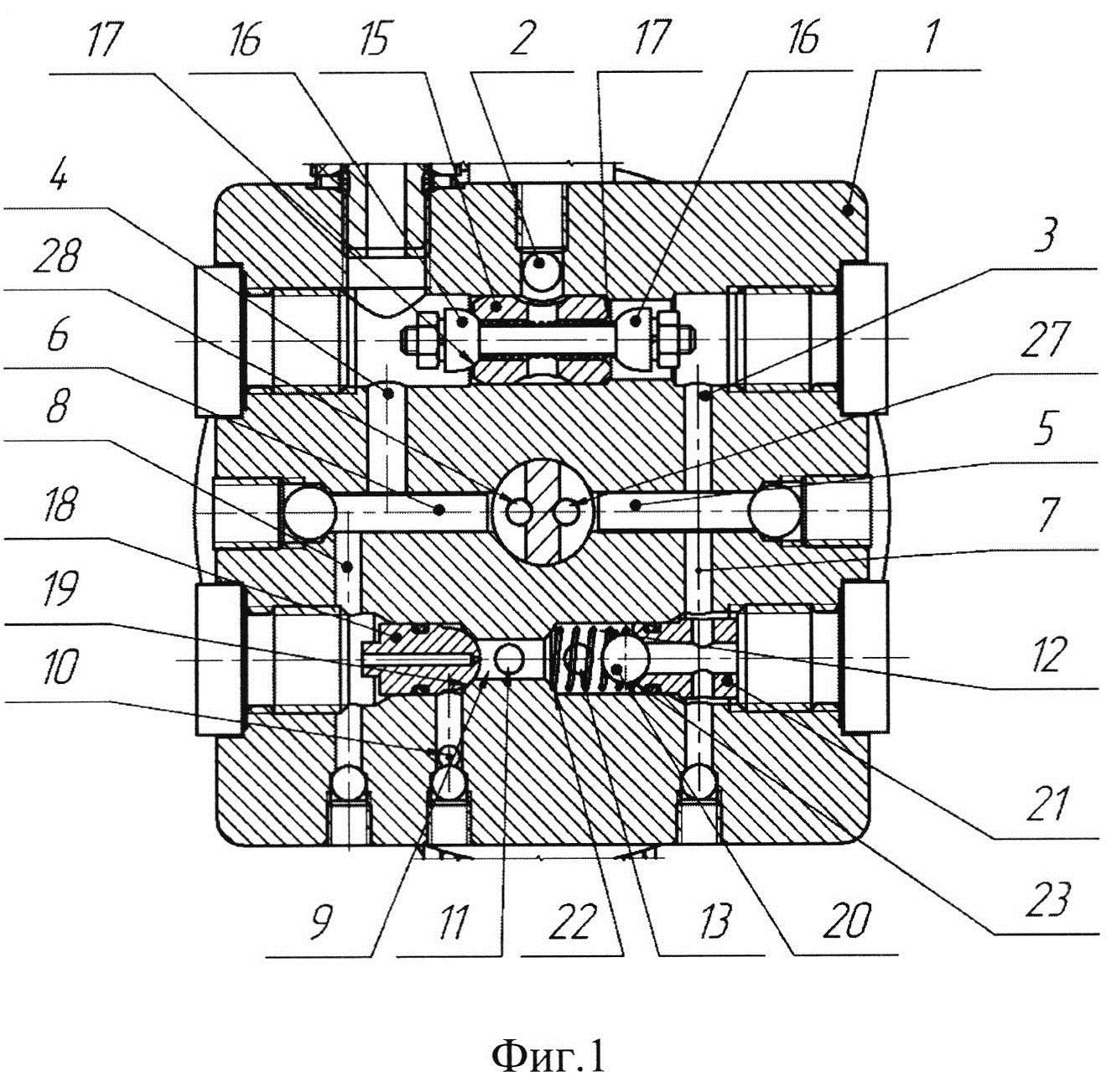
Description
Полезная модель относится к транспортному машиностроению, в частности, к распределительному узлу гидравлического насоса механизма опрокидывания кабины транспортного средства.The utility model relates to transport engineering, in particular, to the distribution unit of the hydraulic pump of the vehicle cabin tipping mechanism.
Наиболее близким к заявляемому техническому решению по совокупности существенных признаков является распределительный узел насоса, известный из интегрированного цилиндра электрогидравлического насоса опрокидывания кабины, содержащий всасывающий, логический и предохранительный клапаны, расположенные в масляных каналах корпуса распределительного узла. Клапаны содержат запорные элементы, рабочие поверхности которых контактируют с седлами клапанов. Рабочие поверхности запорных элементов всасывающего и логического клапанов выполнены коническими, седла клапанов выполнены с острой кромкой. Запирание всасывающего и логического клапанов происходит конус по кромке, а предохранительного клапана - сфера по кромке (см. CN104925146, МПК B62D 33/063, опубл. 23.09.2015 г.).The closest to the claimed technical solution in terms of essential features is the pump distribution unit, known from the integrated cylinder of the electro-hydraulic cab tilting pump, containing suction, logic and safety valves located in the oil channels of the distribution unit housing. The valves contain locking elements, the working surfaces of which are in contact with the valve seats. The working surfaces of the shut-off elements of the suction and logic valves are made conical, the valve seats are made with a sharp edge. The suction and logic valves are closed by a cone along the edge, and the safety valve is closed by a sphere along the edge (see CN104925146, IPC B62D 33/063, publ. 23.09.2015).
Недостатком известного технического решения является низкая технологичность, обусловленная тем, что рабочие поверхности запорных элементов всасывающего и логического клапанов выполнены коническими, при этом запирание всасывающего и логического клапанов происходит конус по кромке, а предохранительного клапана - сфера по кромке. Данный вид запирания предъявляет высокие требования к обработке кромки седла клапана. Кромка должна быть острой и с малым полем допуска округлости, для чего необходим специальный инструмент.The disadvantage of the known technical solution is the low manufacturability, due to the fact that the working surfaces of the shut-off elements of the suction and logic valves are made conical, while the suction and logic valves are locked along the edge, and the safety valve is a sphere along the edge. This type of closure places high demands on the processing of the valve seat lip. The edge must be sharp and with a small roundness tolerance, which requires a special tool.
Технической проблемой, на решение которой направлено заявляемое техническое решение, является повышение технологичности конструкции распределительного узла насоса.The technical problem to be solved by the claimed technical solution is to improve the manufacturability of the design of the distribution unit of the pump.
Технический результат заключается в повышении технологичности конструкции распределительного узла насоса и достигается за счет того, что в распределительном узле насоса, содержащем всасывающий, логический и предохранительный клапаны, расположенные в каналах корпуса распределительного узла и содержащие запорные элементы, рабочие поверхности которых контактируют с седлами клапанов, седла клапанов выполнены конической формы, а рабочие поверхности запорных элементов всасывающего и логического клапанов выполнены сферическими.The technical result consists in improving the manufacturability of the design of the pump distribution unit and is achieved due to the fact that in the pump distribution unit, containing suction, logic and safety valves, located in the channels of the distribution unit housing and containing shut-off elements, the working surfaces of which are in contact with the valve seats, the saddles valves are made conical, and the working surfaces of the shut-off elements of the suction and logic valves are spherical.
Отличительные признаки заявляемого технического решения заключаются в том, что седла клапанов выполнены конической формы, а рабочие поверхности запорных элементов всасывающего и логического клапанов выполнены сферическими.Distinctive features of the proposed technical solution are that the valve seats are conical, and the working surfaces of the shut-off elements of the suction and logic valves are spherical.
Выполнение седел клапанов конической формы, а рабочих поверхностей запорных элементов всасывающего и логического клапанов сферическими позволили обеспечить запирание клапанов сфера по конической поверхности, что не требует высокоточной обработки рабочих поверхностей запорных элементов и кромок седел клапанов и специального инструмента, и, как следствие, позволили повысить технологичность конструкции распределительного узла насоса.The execution of the valve seats of a conical shape, and the working surfaces of the shut-off elements of the suction and logic valves as spherical, made it possible to ensure the locking of the sphere valves along the conical surface, which does not require high-precision processing of the working surfaces of the shut-off elements and the edges of the valve seats and special tools, and, as a result, made it possible to improve manufacturability design of the pump distribution unit.
Таким образом, заявленная совокупность существенных признаков позволила повысить технологичность конструкции распределительного узла насоса.Thus, the claimed set of essential features has made it possible to improve the manufacturability of the design of the pump distribution unit.
Заявляемая полезная модель поясняется чертежами:The claimed utility model is illustrated by drawings:
фиг.1 - распределительный узел насоса, в разрезе всасывающего и логического клапанов;Fig.1 - distribution unit of the pump, in the context of the suction and logic valves;
фиг.2 - то же, в разрезе предохранительного клапана.figure 2 - the same, in the context of the safety valve.
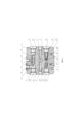
Распределительный узел насоса содержит корпус 1 с внутренними каналами 2, 3, 4, 5, 6, 7, 8, 9, 10, 11, 12, 13, 14 сообщенные между собой. Между каналами 3 и 4 расположен всасывающий клапан 15, предназначенный для изолирования напорной и всасывающей полостей насоса и сообщения всасывающей полости с баком через канал 2. Всасывающий клапан 15 содержит два запорных элемента 16, установленные на концах шпильки с возможностью осевого перемещения. Рабочие поверхности запорных элементов 16 выполнены сферическими и контактируют с седлами 17 клапана. Седла 17 выполнены конической формы. Всасывающий клапан 15 посредством каналов 3, 7 и 4, 8 сообщен с логическим клапаном.The distribution unit of the pump contains a
Логический клапан предназначен для управления потоком жидкости при выдвижении и втягивании гидроцилиндра. Логический клапан содержит запорный элемент 18 и переключающий элемент. Запорный элемент 18 выполнен с внутренним каналом, сообщающим канал 8 с каналами 9 и 12, которые, в свою очередь, сообщены с каналами 11 и 13, соединенные с поршневой и штоковой полостями гидроцилиндра соответственно. Рабочая поверхность запорного элемента 18 выполнена сферической и контактирует с седлом 19, выполненным конической формы. Переключающий элемент состоит из шарика 20, пружины и втулки 21. Шарик 20 размещен в канале 12 во внутренней полости пружины с возможностью осевого перемещения и контактирует с седлами 22 и 23. Втулка 21 выполнена с внутренними пересекающимися каналами, сообщающими канал 12 с каналом 7.The logic valve is designed to control the flow of fluid when extending and retracting the hydraulic cylinder. The logic valve comprises a shut-
Канал 13 сообщен с каналом 14, в котором расположен предохранительный клапан 24. Предохранительный клапан 24 предназначен для защиты узлов насоса от избыточного давления и содержит подпружиненный запорный элемент, выполненный в виде шарика 25, контактирующий с седлом 26, выполненным конической формы.Channel 13 communicates with
Запирание клапанов распределительного узла происходит сфера по конической поверхности.The valves of the distribution unit are closed by a sphere along a conical surface.
Распределительный узел насоса работает следующим образом.Distribution pump works as follows.
При вращении ротора насоса против часовой стрелки (при выдвижении гидроцилиндра) рабочая жидкость из бака по каналу 2 и через каналы 3 и 5 поступает в канал 27 оси насоса. Из канала 28 оси насоса по каналу 6 рабочая жидкость под давлением поступает в каналы 4 и 8. Рабочая жидкость под давлением в канале 4 прижимает запорный элемент 16 всасывающего клапана 15 к своему седлу 17 и изолирует канал 4 от канала 3. Далее рабочая жидкость по каналу 8 и через канал запорного элемента 18 логического клапана поступает в каналы 9 и 12, прижимая шарик 20 к седлу 23, и изолирует канал 7 от канала 12. Далее рабочая жидкость из каналов 9 и 12 поступает в каналы 11 и 13, соединенные с поршневой и штоковой полостями гидроцилиндра соответственно. Канал 13 сообщен с каналом 14 предохранительного клапана 24.When the pump rotor rotates counterclockwise (when the hydraulic cylinder is extended), the working fluid from the tank through
При превышении давления в напорном канале 6 выше настройки предохранительного клапана 24, рабочая жидкость под давлением в канале 14 отодвигает шарик 25 от седла 26 и канал 14 соединяется с каналом 2 бака. При этом часть рабочей жидкости попадает вновь во всасывающий канал 5, пока давление в канале 6 не снизится ниже настройки предохранительного клапана 24. При снижении давления в канале 14 шарик 25, под действием пружины, прижимается к седлу 26, запирая канал 14.When the pressure in the
При вращении ротора насоса по часовой стрелке (при втягивании гидроцилиндра) напорная и всасывающая полости насоса меняются местами, и рабочая жидкость из бака по каналу 2 и через каналы 4 и 6 поступает в канал 28 оси насоса. Из канала 27 оси насоса по каналу 5 рабочая жидкость под давлением поступает в каналы 3 и 7. Рабочая жидкость под давлением в канале 3 прижимает запорный элемент 16 всасывающего клапана 15 к своему седлу 17 и изолирует канал 3 от канала 4. Далее масло по каналу 7 через каналы втулки 21 переключающего элемента поступает в канал 12, прижимая шарик 20 к седлу 22, и изолирует канал 12 от канала 9, то есть штоковую и поршневую полости гидроцилиндра. Далее рабочая жидкость из канала 12 через канал 13 поступает в штоковую полость гидроцилиндра. При этом из поршневой полости гидроцилиндра рабочая жидкость через канал 11 поступает в канал 9, открывает запорный элемент 18 перемещая его влево, далее рабочая жидкость через канал 10 сливается в бак.When the pump rotor rotates clockwise (when the hydraulic cylinder is retracted), the pressure and suction cavities of the pump change places, and the working fluid from the tank through
При превышении давления в напорном канале 5 выше настройки предохранительного клапана 24 рабочая жидкость под давлением через каналы 7, 12 и 13 поступает в канал 14, отодвигает шарик 25 от седла 26 и канал 14 соединяется с каналом 2. При этом, часть рабочей жидкости попадает вновь во всасывающий канал 6 пока давление в канале 5 не снизится ниже настройки предохранительного клапана 24. При снижении давления в канале 5, шарик 25 под действием пружины прижимается к седлу 26 запирая канал 5.When the pressure in the
Заявляемое техническое решение позволило повысить технологичность конструкции распределительного узла насоса.The proposed technical solution has improved the manufacturability of the design of the distribution unit of the pump.
Заявляемое техническое решение может быть изготовлено на стандартном оборудовании с использованием современных технологий и материалов.The proposed technical solution can be manufactured on standard equipment using modern technologies and materials.
Claims (1)
Publications (1)
| Publication Number | Publication Date |
|---|---|
| RU217841U1 true RU217841U1 (en) | 2023-04-20 |
Family
ID=
Citations (5)
| Publication number | Priority date | Publication date | Assignee | Title |
|---|---|---|---|---|
| RU2310104C2 (en) * | 2005-08-09 | 2007-11-10 | ООО "Научно-производственное предприятие "Омикрон" | Flow regulator |
| RU2319054C2 (en) * | 2006-11-01 | 2008-03-10 | Военный инженерно-технический университет | Valving system for alarm shutoff |
| RU2320903C1 (en) * | 2006-06-20 | 2008-03-27 | Открытое акционерное общество "Павловский машиностроительный завод ВОСХОД"-ОАО "ПМЗ ВОСХОД" | Sectional hydraulic distributor with mechanical manual control and working section of sectional hydraulic distributor with mechanical manual control |
| EP1843048B1 (en) * | 2006-04-07 | 2010-07-14 | Weber-Hydraulik GmbH | Fluid cylinder assembly |
| CN104925146A (en) * | 2015-04-01 | 2015-09-23 | 安徽德鸿机件制造有限公司 | Integrated overturn electric hydraulic pump cylinder for cab of heavy truck |
Patent Citations (5)
| Publication number | Priority date | Publication date | Assignee | Title |
|---|---|---|---|---|
| RU2310104C2 (en) * | 2005-08-09 | 2007-11-10 | ООО "Научно-производственное предприятие "Омикрон" | Flow regulator |
| EP1843048B1 (en) * | 2006-04-07 | 2010-07-14 | Weber-Hydraulik GmbH | Fluid cylinder assembly |
| RU2320903C1 (en) * | 2006-06-20 | 2008-03-27 | Открытое акционерное общество "Павловский машиностроительный завод ВОСХОД"-ОАО "ПМЗ ВОСХОД" | Sectional hydraulic distributor with mechanical manual control and working section of sectional hydraulic distributor with mechanical manual control |
| RU2319054C2 (en) * | 2006-11-01 | 2008-03-10 | Военный инженерно-технический университет | Valving system for alarm shutoff |
| CN104925146A (en) * | 2015-04-01 | 2015-09-23 | 安徽德鸿机件制造有限公司 | Integrated overturn electric hydraulic pump cylinder for cab of heavy truck |
Similar Documents
| Publication | Publication Date | Title |
|---|---|---|
| JP6082548B2 (en) | Variable displacement pump | |
| DE3240542C3 (en) | Tandem master cylinder | |
| US2826149A (en) | Booster pump | |
| US2752947A (en) | Balanced valve | |
| CN106065957B (en) | Switching valve and connecting rod with switching valve | |
| CN109804150B (en) | Link with adjustable link length using mechanical operation | |
| CN106894962A (en) | A kind of high-pressure high-flow hydraulic planger pump | |
| US2360839A (en) | Shuttle valve | |
| CN108425745B (en) | Connecting rod check valve for variable compression ratio internal combustion engine and connecting rod with the check valve | |
| DE102016114978A1 (en) | Connecting rod for a variable compression internal combustion engine | |
| RU217841U1 (en) | PUMP DISTRIBUTION ASSEMBLY | |
| GB2028953A (en) | An Internal Combustion Engine with Exhaust Braking | |
| US3227094A (en) | High pressure hydraulic pumps | |
| CN110645385B (en) | Check valve for a connecting rod of an internal combustion engine with variable compression ratio and connecting rod with a check valve | |
| RU217840U1 (en) | DISTRIBUTION UNIT LOGIC VALVE | |
| CN101963164A (en) | Accumulator replenishing valve of full-hydraulic braking system of engineering machinery | |
| JPS6139842Y2 (en) | ||
| DE102018213227A1 (en) | Piston pump for brake system | |
| EP3404232B1 (en) | Connecting rod for a combustion engine with variable compression | |
| US3433240A (en) | Hydraulic pressure relief valve unit | |
| US20190101054A1 (en) | Filter element for a connecting rod and connecting rod for an internal combustion engine with variable compression | |
| US3454028A (en) | Hydraulic valve unit for use in hydraulic systems | |
| RU217861U9 (en) | SUCTION VALVE, DISTRIBUTION UNIT | |
| RU217861U1 (en) | INTAKE VALVE | |
| JP2004044705A (en) | Hydraulic cylinder |