RU2178109C2 - Steplessly adjustable gearbox control system - Google Patents
Steplessly adjustable gearbox control system Download PDFInfo
- Publication number
- RU2178109C2 RU2178109C2 RU98120705/28A RU98120705A RU2178109C2 RU 2178109 C2 RU2178109 C2 RU 2178109C2 RU 98120705/28 A RU98120705/28 A RU 98120705/28A RU 98120705 A RU98120705 A RU 98120705A RU 2178109 C2 RU2178109 C2 RU 2178109C2
- Authority
- RU
- Russia
- Prior art keywords
- clutch
- control
- pressure
- variator
- mode
- Prior art date
Links
Images

Classifications
-
- F—MECHANICAL ENGINEERING; LIGHTING; HEATING; WEAPONS; BLASTING
- F16—ENGINEERING ELEMENTS AND UNITS; GENERAL MEASURES FOR PRODUCING AND MAINTAINING EFFECTIVE FUNCTIONING OF MACHINES OR INSTALLATIONS; THERMAL INSULATION IN GENERAL
- F16H—GEARING
- F16H61/00—Control functions within control units of change-speed- or reversing-gearings for conveying rotary motion ; Control of exclusively fluid gearing, friction gearing, gearings with endless flexible members or other particular types of gearing
- F16H61/66—Control functions within control units of change-speed- or reversing-gearings for conveying rotary motion ; Control of exclusively fluid gearing, friction gearing, gearings with endless flexible members or other particular types of gearing specially adapted for continuously variable gearings
- F16H61/664—Friction gearings
-
- F—MECHANICAL ENGINEERING; LIGHTING; HEATING; WEAPONS; BLASTING
- F16—ENGINEERING ELEMENTS AND UNITS; GENERAL MEASURES FOR PRODUCING AND MAINTAINING EFFECTIVE FUNCTIONING OF MACHINES OR INSTALLATIONS; THERMAL INSULATION IN GENERAL
- F16H—GEARING
- F16H37/00—Combinations of mechanical gearings, not provided for in groups F16H1/00 - F16H35/00
- F16H37/02—Combinations of mechanical gearings, not provided for in groups F16H1/00 - F16H35/00 comprising essentially only toothed or friction gearings
- F16H37/06—Combinations of mechanical gearings, not provided for in groups F16H1/00 - F16H35/00 comprising essentially only toothed or friction gearings with a plurality of driving or driven shafts; with arrangements for dividing torque between two or more intermediate shafts
- F16H37/08—Combinations of mechanical gearings, not provided for in groups F16H1/00 - F16H35/00 comprising essentially only toothed or friction gearings with a plurality of driving or driven shafts; with arrangements for dividing torque between two or more intermediate shafts with differential gearing
- F16H37/0833—Combinations of mechanical gearings, not provided for in groups F16H1/00 - F16H35/00 comprising essentially only toothed or friction gearings with a plurality of driving or driven shafts; with arrangements for dividing torque between two or more intermediate shafts with differential gearing with arrangements for dividing torque between two or more intermediate shafts, i.e. with two or more internal power paths
- F16H37/084—Combinations of mechanical gearings, not provided for in groups F16H1/00 - F16H35/00 comprising essentially only toothed or friction gearings with a plurality of driving or driven shafts; with arrangements for dividing torque between two or more intermediate shafts with differential gearing with arrangements for dividing torque between two or more intermediate shafts, i.e. with two or more internal power paths at least one power path being a continuously variable transmission, i.e. CVT
- F16H37/086—CVT using two coaxial friction members cooperating with at least one intermediate friction member
-
- F—MECHANICAL ENGINEERING; LIGHTING; HEATING; WEAPONS; BLASTING
- F16—ENGINEERING ELEMENTS AND UNITS; GENERAL MEASURES FOR PRODUCING AND MAINTAINING EFFECTIVE FUNCTIONING OF MACHINES OR INSTALLATIONS; THERMAL INSULATION IN GENERAL
- F16H—GEARING
- F16H61/00—Control functions within control units of change-speed- or reversing-gearings for conveying rotary motion ; Control of exclusively fluid gearing, friction gearing, gearings with endless flexible members or other particular types of gearing
- F16H61/04—Smoothing ratio shift
- F16H61/06—Smoothing ratio shift by controlling rate of change of fluid pressure
- F16H61/061—Smoothing ratio shift by controlling rate of change of fluid pressure using electric control means
-
- F—MECHANICAL ENGINEERING; LIGHTING; HEATING; WEAPONS; BLASTING
- F16—ENGINEERING ELEMENTS AND UNITS; GENERAL MEASURES FOR PRODUCING AND MAINTAINING EFFECTIVE FUNCTIONING OF MACHINES OR INSTALLATIONS; THERMAL INSULATION IN GENERAL
- F16H—GEARING
- F16H15/00—Gearings for conveying rotary motion with variable gear ratio, or for reversing rotary motion, by friction between rotary members
- F16H15/02—Gearings for conveying rotary motion with variable gear ratio, or for reversing rotary motion, by friction between rotary members without members having orbital motion
- F16H15/04—Gearings providing a continuous range of gear ratios
- F16H15/06—Gearings providing a continuous range of gear ratios in which a member A of uniform effective diameter mounted on a shaft may co-operate with different parts of a member B
- F16H15/32—Gearings providing a continuous range of gear ratios in which a member A of uniform effective diameter mounted on a shaft may co-operate with different parts of a member B in which the member B has a curved friction surface formed as a surface of a body of revolution generated by a curve which is neither a circular arc centered on its axis of revolution nor a straight line
- F16H15/36—Gearings providing a continuous range of gear ratios in which a member A of uniform effective diameter mounted on a shaft may co-operate with different parts of a member B in which the member B has a curved friction surface formed as a surface of a body of revolution generated by a curve which is neither a circular arc centered on its axis of revolution nor a straight line with concave friction surface, e.g. a hollow toroid surface
- F16H15/38—Gearings providing a continuous range of gear ratios in which a member A of uniform effective diameter mounted on a shaft may co-operate with different parts of a member B in which the member B has a curved friction surface formed as a surface of a body of revolution generated by a curve which is neither a circular arc centered on its axis of revolution nor a straight line with concave friction surface, e.g. a hollow toroid surface with two members B having hollow toroid surfaces opposite to each other, the member or members A being adjustably mounted between the surfaces
- F16H2015/383—Gearings providing a continuous range of gear ratios in which a member A of uniform effective diameter mounted on a shaft may co-operate with different parts of a member B in which the member B has a curved friction surface formed as a surface of a body of revolution generated by a curve which is neither a circular arc centered on its axis of revolution nor a straight line with concave friction surface, e.g. a hollow toroid surface with two members B having hollow toroid surfaces opposite to each other, the member or members A being adjustably mounted between the surfaces with two or more sets of toroid gearings arranged in parallel
-
- F—MECHANICAL ENGINEERING; LIGHTING; HEATING; WEAPONS; BLASTING
- F16—ENGINEERING ELEMENTS AND UNITS; GENERAL MEASURES FOR PRODUCING AND MAINTAINING EFFECTIVE FUNCTIONING OF MACHINES OR INSTALLATIONS; THERMAL INSULATION IN GENERAL
- F16H—GEARING
- F16H37/00—Combinations of mechanical gearings, not provided for in groups F16H1/00 - F16H35/00
- F16H37/02—Combinations of mechanical gearings, not provided for in groups F16H1/00 - F16H35/00 comprising essentially only toothed or friction gearings
- F16H37/06—Combinations of mechanical gearings, not provided for in groups F16H1/00 - F16H35/00 comprising essentially only toothed or friction gearings with a plurality of driving or driven shafts; with arrangements for dividing torque between two or more intermediate shafts
- F16H37/08—Combinations of mechanical gearings, not provided for in groups F16H1/00 - F16H35/00 comprising essentially only toothed or friction gearings with a plurality of driving or driven shafts; with arrangements for dividing torque between two or more intermediate shafts with differential gearing
- F16H37/0833—Combinations of mechanical gearings, not provided for in groups F16H1/00 - F16H35/00 comprising essentially only toothed or friction gearings with a plurality of driving or driven shafts; with arrangements for dividing torque between two or more intermediate shafts with differential gearing with arrangements for dividing torque between two or more intermediate shafts, i.e. with two or more internal power paths
- F16H37/084—Combinations of mechanical gearings, not provided for in groups F16H1/00 - F16H35/00 comprising essentially only toothed or friction gearings with a plurality of driving or driven shafts; with arrangements for dividing torque between two or more intermediate shafts with differential gearing with arrangements for dividing torque between two or more intermediate shafts, i.e. with two or more internal power paths at least one power path being a continuously variable transmission, i.e. CVT
- F16H2037/088—Power split variators with summing differentials, with the input of the CVT connected or connectable to the input shaft
-
- F—MECHANICAL ENGINEERING; LIGHTING; HEATING; WEAPONS; BLASTING
- F16—ENGINEERING ELEMENTS AND UNITS; GENERAL MEASURES FOR PRODUCING AND MAINTAINING EFFECTIVE FUNCTIONING OF MACHINES OR INSTALLATIONS; THERMAL INSULATION IN GENERAL
- F16H—GEARING
- F16H61/00—Control functions within control units of change-speed- or reversing-gearings for conveying rotary motion ; Control of exclusively fluid gearing, friction gearing, gearings with endless flexible members or other particular types of gearing
- F16H61/04—Smoothing ratio shift
- F16H61/06—Smoothing ratio shift by controlling rate of change of fluid pressure
- F16H61/065—Smoothing ratio shift by controlling rate of change of fluid pressure using fluid control means
- F16H61/068—Smoothing ratio shift by controlling rate of change of fluid pressure using fluid control means using an orifice control valve
Abstract
Description
Настоящее изобретение относится к бесступенчато-регулируемым коробкам передач (БРКП), используемым, например, в приводимом в движение с помощью двигателя средстве передвижения, а также к системам гидравлического управления для подобных (БРКП). The present invention relates to continuously variable transmissions (BRKP) used, for example, in a vehicle driven by a motor, and also to hydraulic control systems for such (BRKP).
Известны коробки передач, использующие тип вариатора тяги качения с тороидальной канавкой для реализации функций бесступенчато-регулируемой передачи и муфты для перевода коробки передач в один или другой из двух рабочих режимов. Known gearboxes using the type of variator traction with a toroidal groove to implement the functions of a continuously variable transmission and clutch to translate the gearbox into one or the other of two operating modes.
Обычно подобные муфты конструируют с перемежающимися фрикционными дисками, приводимыми в действие с помощью гидравлических плунжеров. Для предотвращения избыточного сопротивления при расцеплении диски принудительно разделяются посредством встроенных в муфту "отталкивающих" пружин. Typically, such couplings are constructed with alternating friction discs driven by hydraulic plungers. To prevent excessive resistance during disengagement, the disks are forcibly separated by means of "repelling" springs integrated in the clutch.
Когда муфта пониженного режима находится в состоянии сцепления, например для нейтрального положения реверсного движения и движения средства передвижения вперед с небольшими скоростями, передача управляющего воздействия от вариатора к выходному валу коробки передач производится через преобразующую планетарную зубчатую передачу, в которой водило планетарной передачи перемещается входным валом, при этом выходной диск вариатора приводит в движение центральное колесо планетарной зубчатой передачи, а зубчатый венец планетарной передачи соединен с выходным валом коробки передач. When the reduced clutch is in a clutch state, for example, for a neutral position of reverse movement and movement of the vehicle forward at low speeds, control is transmitted from the variator to the output shaft of the gearbox through a transforming planetary gear transmission in which the planetary gear carrier is moved by the input shaft, while the output disk of the variator drives the central wheel of the planetary gear drive, and the ring gear of the planetary gear and connected to the output shaft of the gearbox.
Когда ролики установлены в положения передаточного отношения наивысшей скорости, влияние центрального колеса планетарной передачи преобладает, приводя выходной вал коробки передач в движение в обратном направлении. При смещении роликов от этих положений они проходят через позицию нейтрального зацепления, в которой равные и противоположно направленные воздействия центрального колеса и водила планетарной передачи компенсируют друг друга, давая нулевое приводное воздействие. В дальнейшем, по мере того как ролики смещаются для функционирования вариатора с передаточным отношением постепенно уменьшающейся скорости, прямое приводное движение от планетарного водила преобладает в увеличивающейся степени. В результате этого, когда передаточное отношение вариатора достигнет своего нижнего предела, то есть минимального обратного воздействия, центральное колесо, планетарное водило и ее зубчатый венец - все вращаются полностью согласованно. Это приводит к тому, что две компоненты муфты повышенного режима также вращаются с одними и теми же скоростями, при этом говорят, что коробка передач работает при синхронном передаточном отношении. When the rollers are set to the highest gear ratio, the influence of the central planetary gear wheel prevails, driving the gearbox output shaft in reverse. When the rollers are displaced from these positions, they pass through the neutral gearing position, in which equal and oppositely directed effects of the central wheel and the planetary gear carrier compensate each other, giving a zero drive effect. In the future, as the rollers are shifted for the operation of the variator with a gear ratio of a gradually decreasing speed, the direct drive movement from the planetary carrier will prevail in an increasing degree. As a result of this, when the gear ratio of the variator reaches its lower limit, that is, the minimum reverse impact, the central wheel, planetary carrier and its gear ring - all rotate completely in concert. This leads to the fact that the two components of the increased clutch also rotate at the same speeds, while they say that the gearbox operates with a synchronous gear ratio.
Очевидно, что при установлении последнего состояния муфта пониженного режима может расцепляться в тот же момент времени (или позже), когда муфта повышенного режима переходит в сцепление, чтобы обеспечить изменение режима с минимальными проскальзываниями, ударными воздействиями или износом. Obviously, when the latter state is established, the reduced clutch can be disengaged at the same time (or later), when the high clutch goes into engagement to provide a change in mode with minimal slippage, impact or wear.
При работе в повышенном режиме выходной вал коробки передач приводится в движение через цепь с фиксированным передаточным отношением от выходного диска вариатора, и движение роликов вариатора обратно в их положения передаточного отношения наивысшей скорости позволяет коробке передач достигать все более высоких передаточных отношений скорости движения вперед вплоть до наиболее высокой передачи. Очевидно, что в этих известных системах синхронное изменение режима может иметь место только при одном конкретном значении передаточного отношения коробки передач, поскольку только при этом значении приводящаяся в рабочее состояние муфта не имеет относительного движения ее элементов и может быть приведена в сцепление в отсутствие заметного риска возникновения ударной нагрузки переключения. Это справедливо как для перехода из пониженного режима к повышенному режиму, как это было раскрыто выше, так и для обратного направления. Тем не менее, поскольку на практике муфтам требуется конечное время для заполнения и сцепления, для обеспечения посредством БРКП плавного и непрерывного изменения передаточного отношения процесс заполнения должен быть начат соответственно заблаговременно. When operating in increased mode, the output shaft of the gearbox is driven through a chain with a fixed gear ratio from the output disk of the variator, and the movement of the variator rollers back to their highest gear ratio positions allows the gearbox to achieve ever higher forward speed ratios up to the most high gear. Obviously, in these known systems, a synchronous change of mode can take place only at one specific value of the gear ratio of the gearbox, since only at this value the clutch being put into operation does not have the relative movement of its elements and can be brought into engagement in the absence of a noticeable risk of occurrence shock loading switching. This is true both for the transition from a reduced mode to an increased mode, as was described above, and for the opposite direction. Nevertheless, since in practice the couplings require a finite time for filling and coupling, in order to ensure a smooth and continuous change in the gear ratio by means of the BCF, the filling process must be started accordingly in advance.
Применяемая в настоящее время для этой цели стратегия в этих системах обеспечивает сцепление муфты в два этапа. The strategy currently used for this purpose in these systems provides clutch engagement in two stages.
На первом этапе при приближении коробки передач к синхронному передаточному отношению для "мягкого заполнения" муфты до давления, едва обеспечивающего преодоление усилий, создаваемых "отталкивающими" пружинами, и сведения фрикционных дисков. Требуемый для осуществления этой цели ограниченный поток масла поступает из потока смазочной жидкости ниже по потоку после регулирующих клапанов системы для обеспечения потока жидкости большого объема и низкого давления к плунжерам, приводящим в действие муфту. Поскольку подаваемое на муфту низкое давление недостаточно для создания значительной емкости муфты, мягкое заполнение муфты может быть начато в любое подходящее время, обеспечивающее при достижении коробкой передач синхронного передаточного отношения заполнения муфты. At the first stage, when the gearbox is approaching the synchronous gear ratio for “soft filling” the clutch to a pressure that barely overcomes the forces created by the “repellent” springs and reduces friction disks. The limited oil flow required to accomplish this goal comes from the lubricant fluid stream downstream of the control valves of the system to provide a large volume and low pressure fluid flow to the plungers driving the clutch. Since the low pressure applied to the clutch is not sufficient to create a significant clutch capacity, soft clutch filling can be started at any suitable time, ensuring that the gearbox reaches the synchronous gear ratio to fill the clutch.
На втором этапе, как только передаточное отношение коробки передач находится в пределах допустимого значения синхронного передаточного отношения муфта и мягко заполнена как описано выше, гидравлическая система переходит в режим "жесткого заполнения" муфты при существенно большем давлении и для полного сцепления муфты и перевода коробки передач в работу в повышенном режиме. Этот второй этап процесса требует весьма небольшого потока масла и вследствие этого является быстрым и не имеет разрыва управления давлением. In the second stage, as soon as the gear ratio is within the permissible value of the synchronous gear ratio of the clutch and is softly filled as described above, the hydraulic system switches to the “hard fill” mode of the clutch at a significantly higher pressure and to completely engage the clutch and transfer the gearbox to work in high mode. This second step of the process requires a very small oil flow and is therefore quick and has no pressure control gap.
Как уже отмечалось выше, если последовательность произведена правильно, обеспечивается идеальная смена режима, как, например, будет, когда процесс заполнения ранее завершен, поскольку затем система могла ожидать синхронизма. Однако, если заполнение запаздывает, как иногда бывает, коробка передач уже пройдет состояние синхронного передаточного отношения до того, как будет предпринято какое-либо действие, в результате чего создается ситуация, когда удовлетворительная смена режима почти невозможна. В последнем случае жесткое заполнение муфты будет происходить при существенной ошибке передаточного отношения коробки передач, что приводит к появлению во время перехода от одного режима работы коробки передач к другому заметных ударных механических нагрузок. As already noted above, if the sequence is performed correctly, an ideal change of mode is ensured, as, for example, will be when the filling process was previously completed, since then the system could expect synchronism. However, if the filling is delayed, as sometimes happens, the gearbox will already pass the state of synchronous gear ratio before any action is taken, as a result of which a situation is created when a satisfactory change of mode is almost impossible. In the latter case, a rigid filling of the clutch will occur when there is a significant error in the gear ratio of the gearbox, which leads to the appearance of noticeable shock mechanical loads during the transition from one gearbox operation mode to another.
Целью настоящего изобретения является уменьшение влияния, а по возможности и исключение проблем, связанных с вышеупомянутыми компоновками. The aim of the present invention is to reduce the impact, and if possible, to eliminate the problems associated with the above arrangements.
Соответственно, настоящее изобретение обеспечивает системы управления для многорежимной бесступенчато-регулируемой коробки передач, имеющей в качестве приводного первичный двигатель и обеспечивающей выходное приводное движение, при этом система управления содержит первую и вторую муфты изменения режима и средство для инициирования сцепления муфты, иначе находящейся в расцеплении, в течение изменения режима, упомянутая система управления дополнительно содержит:
первое средство регулирования для регулирования давления приложения одной или другой муфты, и
второе средство регулирования для регулирования роликов вариатора, отличающуюся тем, что первое и второе средства регулирования являются действующими независимо друг от друга, посредством чего достигается активное управление изменением режима.Accordingly, the present invention provides control systems for a multimode continuously variable gearbox having a prime mover as the drive and providing output drive movement, the control system comprising first and second mode clutches and means for initiating clutch clutch otherwise disengaged, during a mode change, said control system further comprises:
first control means for regulating the application pressure of one or the other coupling, and
second control means for adjusting the variator rollers, characterized in that the first and second control means are independent of each other, thereby actively controlling the change of mode.
Предпочтительно первая и вторая муфты режима содержат гидравлически приводимые в действие муфты, использующие абсолютные давления в контуре регулирования, а управление вариатором использует дифференциальные давления в упомянутом контуре регулирования. Preferably, the first and second mode couplings comprise hydraulically actuated couplings using absolute pressures in the control loop, and the variator control uses differential pressures in said control loop.
Преимущественно каждая муфта имеет этап активного сцепления, обеспечиваемый посредством соединения муфты с давлением отставания в контуре регулирования, и этап полного сцепления, обеспечиваемый посредством соединения муфты с давлением опережения в контуре. Advantageously, each clutch has an active clutch step provided by connecting the clutch to a lag pressure in the control loop and a full clutch step provided by connecting the clutch with a lead pressure in the loop.
В работе каждая муфта операционно соединена с меньшим из двух давлений, используемых для управления вариатором, и по меньшей мере первоначально управляется им. In operation, each clutch is operatively connected to, and at least initially controlled by, the smaller of the two pressures used to control the variator.
Предпочтительно каждая муфта операционно соединена с большим из двух давлений, используемых для управления вариатором, последующим за ней соединяемым с меньшим давлением, используемым здесь. Система управления дополнительно содержит средство подачи для обеспечения подачи рабочей жидкости к каждой муфте для изменения между двумя давлениями в контуре регулирования. Preferably, each clutch is operatively connected to the larger of the two pressures used to control the variator, which is then connected to the lower pressure used here. The control system further comprises a supply means for supplying a working fluid to each coupling for changing between two pressures in the control loop.
Преимущественно система управления также содержит средство задания последовательности для вызова функционирования и завершения этапа активного управления до начала этапа полного сцепления. Advantageously, the control system also comprises means for defining a sequence for triggering operation and completing the active control step before the start of the full engagement step.
Предпочтительно система управления также содержит электронное средство управления для инициирования функционирования муфты до изменения диапазона. Preferably, the control system also includes electronic control means for initiating the operation of the clutch before changing the range.
В конкретном предпочтительном варианте осуществления система управления дополнительно содержит средство контроля для контроля по меньшей мере одной характеристики, связанной с функционированием вариатора, для определения посредством этого, до достижения вариатором синхронного передаточного отношения, что необходимо изменение передаточного отношения и соответствующего сигнализирования электронному средству управления. In a particular preferred embodiment, the control system further comprises monitoring means for monitoring at least one characteristic related to the operation of the variator, thereby determining, until the variator reaches the synchronous gear ratio, that it is necessary to change the gear ratio and corresponding signaling to the electronic control means.
Предпочтительно упомянутое средство контроля содержит одно или более контрольное устройство для контроля одного или более из скорости двигателя, передаточного отношения вариатора, времени, передаточного отношения коробки передач, времени заполнения муфты и скорости смены изменения одного или другого из них. Preferably, said monitoring means comprises one or more monitoring devices for monitoring one or more of an engine speed, a gear ratio of a variator, a time, a gear ratio of a gearbox, a clutch filling time, and a shift speed of changing one or the other of them.
Настоящее изобретение также обеспечивает многорежимную бесступенчато-регулируемую коробку передач, содержащую вышеописанную систему управления. The present invention also provides a multi-mode continuously variable transmission comprising the above-described control system.
В дополнение к выше сказанному настоящее изобретение также обеспечивает способ задействования системы управления для многорежимной бесступенчато-регулируемой коробкой передач, имеющей первую и вторую муфты изменения режима, этот способ содержит этапы:
первоначального, во время изменения режима, инициирования сцепления муфты, иначе находящейся в расцеплении, до достижения вариатором синхронного передаточного отношения так, что изменяется нагрузка двигателя, создаваемая коробкой передач, посредством чего вызывается изменение режима,
последующего завершения изменения режима работы посредством расцепления муфты, связанной с режимом, из которого была изменена передача, и завершения сцепления муфты, выполняющей сцепления.In addition to the foregoing, the present invention also provides a method for activating a control system for a multi-mode continuously variable gearbox having first and second mode clutches, this method comprising the steps of:
the initial, during the change of mode, the initiation of the clutch of the clutch, otherwise disengaged, until the variator reaches a synchronous gear ratio so that the engine load created by the gearbox changes, whereby the change of mode is caused,
subsequently completing the change of the operating mode by disengaging the clutch associated with the mode from which the gear was changed, and completing the clutch of the clutch.
Предпочтительно муфты содержат гидравлически управляемые муфты, и каждая муфта имеет этап активного сцепления и этап полного сцепления, при этом на активном этапе муфта операционно соединена с давлением отставания в контуре регулирования, а на этапе полного сцепления муфта операционно соединена с давлением опережения в контуре регулирования, причем дополнительно инициируют сцепления муфты посредством первоначального соединения муфты с давлением отставания и завершают сцепление посредством ее соединения с давлением опережения. Preferably, the couplings comprise hydraulically controlled couplings, and each clutch has an active clutch step and a full clutch step, wherein in the active step the clutch is operatively connected to a lag pressure in the control loop, and at the full clutch step, the clutch is operatively connected to an advance pressure in the control loop, additionally initiate the clutch coupling by initially connecting the coupling to the back pressure and complete the clutch by connecting it to the advance pressure.
Предпочтительно вариатор содержит ролики изменения передаточного отношения, каждый из которых связан с соответствующим плунжером гидроцилиндра, причем способ дополнительно содержит этап подачи рабочей жидкости к плунжеру гидроцилиндра таким образом, чтобы ролики реагировали на дифференциальное давление. Preferably, the variator comprises rollers for changing the gear ratio, each of which is connected to a corresponding plunger of the hydraulic cylinder, the method further comprising the step of supplying the working fluid to the plunger of the hydraulic cylinder so that the rollers respond to differential pressure.
Преимущественно способ содержит этап контроля одного или более параметров, связанных с системой управления, коробкой передач или связанными с ними компонентами для определения посредством этого, когда выполнять упомянутые первоначальные и последующий этапы. Advantageously, the method comprises the step of monitoring one or more parameters associated with the control system, gearbox, or related components to determine thereby when to carry out the said initial and subsequent steps.
В другой форме настоящего изобретения предложена гидравлическая система управления для многорежимной бесступенчато-регулируемой коробки передач, имеющей в качестве приводного первичный двигатель и обеспечивающей выходное приводное движение, причем коробка передач имеет гидравлически приводимые в действие первую и вторую муфты изменения режима и вариатор, имеющий ролики, изменяющие передаточное отношение, каждый из которых связан с соответствующим плунжером гидроцилиндра, при этом система имеет в каждый конкретный момент времени источник высокого и низкого гидравлического давления, средство подачи жидкости для подачи рабочей жидкости к каждой муфте, для перехода от жидкости под высоким давлением к жидкости под низким давлением, и подачи рабочей жидкости к плунжеру гидроцилиндра так, чтобы ролики реагировали на дифференциальное давление. In another form of the present invention, there is provided a hydraulic control system for a multimode continuously variable gearbox having a prime mover as the drive and providing output drive movement, the gearbox having hydraulically actuated first and second mode change clutches and a variator having change rollers a gear ratio, each of which is associated with a corresponding plunger of the hydraulic cylinder, while the system has at each particular point in time and a source of high and low hydraulic pressure, a fluid supply means for supplying a working fluid to each coupling, for transferring from a high-pressure fluid to a low-pressure fluid, and supplying a working fluid to the hydraulic cylinder plunger so that the rollers respond to differential pressure.
Ниже варианты осуществления настоящего изобретения, носящие исключительно иллюстративный характер, подробно раскрыты со ссылками на чертежи, на которых
фиг. 1 - схема контура гидравлической системы управления в соответствии с настоящим изобретением;
фиг. 2 - схема БРКП, подлежащей управлению посредством системы, представленной на фиг. 1;
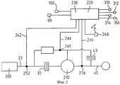
фиг. 3 - схематическое представление системы привода, содержащей аспекты настоящего изобретения; и
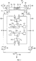
фиг. 4 - упрощенный вариант системы управления, представленной в нижней части фиг. 1.Below, embodiments of the present invention, which are purely illustrative, are described in detail with reference to the drawings, in which
FIG. 1 is a circuit diagram of a hydraulic control system in accordance with the present invention;
FIG. 2 is a diagram of a CDD to be controlled by the system of FIG. 1;
FIG. 3 is a schematic representation of a drive system comprising aspects of the present invention; and
FIG. 4 is a simplified version of the control system shown at the bottom of FIG. 1.
Обратимся сначала к фиг. 2, на которой представлена БРКП 8, содержащая вариатор 10 тяги качения с тороидальной канавкой, содержащей два входных диска 12, 13 (последний скреплен с помощью шпоночного соединения с валом вариатора 15 для ограничения осевого смещения вдоль вала), центральный выходной диск 17 и два набора роликов, регулируемых плунжерами и сцепленных с входными и выходными дисками для передачи крутящего момента между дисками в ответ на нагрузку крутящего момента на вариатор. Для простоты на фиг. 2 представлен лишь один из шести упомянутых роликов, так называемый ведущий ролик 19. Turning first to FIG. 2, which shows BRKP 8, containing a
Как известно из патента Великобритании 2227287, весьма важно, чтобы плунжеры роликов были выравнены так, чтобы они были направлены по существу по касательной к центральной окружности воображаемых торов 21, которые придают ротору часть формы, но с небольшим углом наклона, известным как угол "прогиба" или угол "ролика". As is known from British Patent 2227287, it is very important that the plungers of the rollers are aligned so that they are directed essentially tangentially to the central circumference of the
Входной вал вариатора 15 одним своим концом 23 воспринимает приводное движение от двигателя (не показан) средства передвижения, в то время как к входному диску на другом конце вала вариатора прикладывается осевая нагрузка, создаваемая камерой давления 25, заполненной рабочей жидкостью высокого давления, поступающей из соответствующей линии 27. Давление в линии 27 равно большему из двух давлений в линиях 67, 68, большее из которых применяется как давление управления или давление опережения жидкости для плунжера ролика 29. Жидкость с давлением отставания для плунжера 29 поступает из той линии, 67, 68, которая имеет меньшее давление. Таким образом, следует отметить, что ролик реагирует на величину именно дифференциального давления, воздействующего на его регулирующий плунжер, а не на величины абсолютных давлений в линиях 67 и 68. The input shaft of the
Для работы в повышенном режиме выходной вал 33 коробки передач приводится в движение входным валом вариатора через посредство зубчатой передачи 35, муфты пониженного режима 37 и планетарной зубчатой передачи 39 известного типа. To operate in increased mode, the
Для работы в пониженном режиме вал 33 дополнительно приводится в движение выходным диском 17 вариатора через посредство приводной цепи 41 и муфты 43 повышенного режима. For operation in a reduced mode, the
Цифрой 45 в данном случае обозначен внешний конец вала 33, предназначенный, например, для связи с дифференциалом средства передвижения и колесами. The
Ведущий ролик 19 и пять "ведомых" роликов 47-51, а также их соответствующие регулирующие плунжеры и цилиндры, представлены также на фиг. 1, наряду с двумя муфтами 37 и 43 режимов, обе из которых снабжены отталкивающими пружинами, рассчитанными, чтобы выдержать сводящее диски давление величиной до 3 бар. The
Как можно видеть из фиг. 1, ось 52 ведущего ролика 19 расположена в углублении 53 полого вала 54 плунжера двойного действия 55. Этот плунжер выполнен с противоположными плунжерными головками 56, 57, которые имеют возможность под воздействием гидравлической нагрузки свободно скользить в коаксиальных цилиндрических колпачках 58, 59 и поворачиваться относительно продольной оси вала 54. Плунжер 55 и колпачки 58, 59 совместно образуют плунжер гидроцилиндра 71, связанный с каждым роликом. Очевидно, что эта фигура исключительно схематична. As can be seen from FIG. 1, the
В модификации компонент 55 заменяется плунжером двойного действия с одной головкой, подобному, например, описанному в патенте Великобритании 2227287 и представленному исключительно в целях большей наглядности в составе конструкции, схематично представленной на фиг. 2. In the modification,
Вернемся снова к конструкции с двумя головками, представленной на фиг. 1, отверстия 61, 62 для ввода рабочей жидкости и выводные отверстия 64, 65 для ведущего плунжера выполнены в торцевых и боковых стенках соответствующих колпачков 58, 59 цилиндра и линии 67, 68 создания давления, что позволяет гарантировать, что различные ведомые плунжеры будут вести себя точно также, как и ведущий плунжер 29, так чтобы все шесть роликов вариатора постоянно поддерживались при одинаковом давлении. Returning again to the two-head design shown in FIG. 1, the
Обратимся теперь к гидравлической системе управления 70, которая содержит два независимых масляных насоса 72, 73, подающих рабочую жидкость из резервуара 75 в вышеупомянутые линии 67, 68. Дополнительная линия связи 77 обеспечивает связь этих линий 67, 68 на основе использования двух обратных клапанов 79 и 80, действующих по принципу "пропускания со стороны большего давления", с линией 27 потока на фиг. 2. We now turn to the hydraulic control system 70, which contains two independent oil pumps 72, 73, which supply the working fluid from the reservoir 75 to the
Выводные отверстия 64, 65, выполненные в торцевых колпачках 58, 59 ведущего плунжера, обеспечивают доступ к соответственно левой и правой линиям 82, 83 давления. Они поперечно соединены линией 85, которая обеспечивает на основе использования конструкций 87, 88 связь по принципу "пропускания со стороны большего давления" с контуром 90 полного сцепления для муфт 37 и 43. Вторая поперечная соединительная линия 92 обеспечивает связь на основе использования конструкции 94, 95 по принципу "пропускания со стороны меньшего давления" с контуром активного сцепления 97 для двух муфт. The outlet holes 64, 65, made in the end caps 58, 59 of the leading plunger, provide access to the left and right pressure lines 82, 83, respectively. They are transversely connected by a line 85, which provides, on the basis of the use of structures 87, 88, the principle of “transmission from the higher pressure side” with the full clutch circuit 90 for
Позиции 99, 100 обозначают два электрогидроклапана регулирования давления, которые при совместном использовании образуют первые и вторые средства регулирования для регулирования давления приложения муфты, а также для регулирования подробно описываемым ниже образом роликов вариатора.
Линии 82, 83 сводятся в точке 102 ниже по потоку за двумя этими клапанами, при этом в отходящей от этой точки линии 104 обеспечивается поток жидкости низкого давления, предназначенный для общей смазки коробки передач.
Обращаясь теперь к контурам 90, 97 управления муфтами, следует отметить, что каждый содержит два электрически управляемых электромагнитных клапана 106, 107 и 109, 110, которые могут быть переключены для соединения каждой муфты 37, 43 для "активного заполнения" или "заполнения для полного сцепления" в зависимости от потребности. В соответствии с ситуацией, представленной на фиг. 1, например, переключение клапана 106 обеспечит соединение муфты 37 пониженного режима к контуру активного сцепления 97, тогда как переключения клапана 107, напротив, обеспечит соединение муфты 37 пониженного режима с контуром полного сцепления 90. Клапаны 109 и 110 работают аналогично клапанам 106 и 107, но в отношении муфты 43 повышенного режима. Turning now to clutch control loops 90, 97, it should be noted that each contains two electrically controlled solenoid valves 106, 107 and 109, 110 that can be switched to connect each clutch 37, 43 for “active filling” or “filling for full” clutch "according to need. In accordance with the situation of FIG. 1, for example, switching the valve 106 will provide a connection of the reduced clutch 37 to the active clutch circuit 97, while switching the valve 107, on the contrary, will provide the connection of the reduced clutch 37 to the full clutch circuit 90. The valves 109 and 110 operate similarly to the valves 106 and 107, but with regard to clutch 43 high mode.
Систему завершают два ограничительных (на давление 1 бар) диска 112, 113, установленных в линиях 82, 83 между двумя поперечными соединительными линиями 85, 92. The system is completed by two restrictive (1 bar pressure) discs 112, 113 installed in
Для пояснения принципа функционирования описанного выше варианта осуществления настоящего изобретения, приводимого исключительно в иллюстративных целях, предположим, что первоначально задействована муфта 37, а муфта 43 приводится в действие вместо муфты 37 для обеспечения изменения режима. Затем в сравнении с ситуацией, представленной на фиг. 1 (ни одна из муфт не задействована), будет переключен электромагнитный клапан 107 с тем, чтобы соединить муфту 37 с контуром полного сцепления 90. To explain the principle of operation of the above-described embodiment of the present invention, provided for illustrative purposes only, suppose that the clutch 37 is initially engaged and the clutch 43 is driven instead of the clutch 37 to provide a change of mode. Then, in comparison with the situation shown in FIG. 1 (none of the couplings are engaged), the solenoid valve 107 will be switched so as to connect the clutch 37 to the full clutch circuit 90.
Обратимся теперь к клапанам регулирования давления 99, 100, в типичной ситуации на клапан 99 регулирования давления не подается электрический ток, а на клапан 100 регулирования давления подается электрический ток величиной 1/2 ампера. Это означает, что давление в линии выше по потоку сразу перед клапаном 99 приблизительно будет соответствовать величине обратного давления (2 бара), при этом следующее действие заключается в переключении клапана 109 для заполнения линии между клапаном 109 и муфтой 43 маслом низкого давления. We turn now to the
Для заполнения муфты 43 и сведения дисков муфты в готовность для активного управления изменением режима электрические токи в клапанах 99, 100 увеличивают до 0,1 ампера и 0,6 ампера соответственно для увеличения давления в соседних линиях обычно с 2 бар до 3,6 бара (линия 82) и с 10 бар до 11,6 бара (линия 83). Теперь величина давления в линии 82 достаточна для заполнения муфты 43 повышенного режима со скоростью, которая определяется управляющим электрическим током для клапанов 99, 100. По истечении установленного времени, обычно 1/2 секунды, электроника управления, обозначенная схематично как 220 на фиг. 3, может скажем, сделать вывод о том, что этот этап завершен и система поддерживается в готовности для следующего этапа. Этот последующий этап реализуется, когда электроника управления увеличивает ток для клапанов 99, 100 соответственно до 1 ампера и 1,5 ампера, посредством чего увеличивая давления в соседних линиях до 18 бар (линия 82) и до 26 бар (линия 83). Давление в линии 82 теперь достаточно, чтобы муфта повышенного режима выработала емкость, и это переводит коробку передач на синхронное передаточное отношение. Начальная стадия процесса изменения режима завершается, когда электроника управления измеряет, что передаточное отношение является синхронным. To fill clutch 43 and to keep clutch disks ready for active control of regime change, electric currents in
Следует отметить, что во всех обсужденных выше ситуациях рабочие электрические токи для двух клапанов регулирования давления увеличивают практически на одни и те же величины, поэтому величина разности давлений между двумя линиями 82, 83 остается на 8 барах. Это означает, что положения регулирующих ролики плунжеров в вариаторе остаются не подвержены влиянию того, что происходит у муфт режима. It should be noted that in all the situations discussed above, the working electric currents for the two pressure control valves increase by almost the same values, therefore, the pressure difference between the two
Как уже отмечалось выше в настоящей заявке, ввод обеих муфт изменения режима в полное действие гарантирует, что коробка передач работает при синхронном передаточном отношении, причем именно в этот момент электроника управления должна "принять решение", основываясь на той информации, которую она получает относительно коробки передач, скорости двигателя и положения педали управления дроссельной заслонкой (педаль газа), следует ли вернуть коробку передач в пониженный режим работы или же следует перейти к повышенному режиму работы. Принятие решения о возвращении к пониженному режиму работы потребует просто проделать все вышеописанные действия в обратном порядке (поддерживая на протяжении всего времени разность давлений между линиями 82, 83 соответствующей 8 барам). Следует отметить однако, что если принято решение перевести коробку передач из одного режима в другой, то когда имеет место этот переход, рабочие характеристики вариатора изменятся на обратные, т. е. сторона управляющего давления для регулирующего плунжера ролика будет теперь стороной давления отставания и наоборот. Такое изменение функционально нагрузки сторон предусматривает, чтобы в переходной точке рабочего цикла вариатора упомянутые выше "управляющее" давление и давление "отставания" временно были бы на одной и той же величине. As already noted above in this application, putting both mode change clutches into full operation ensures that the gearbox operates with a synchronous gear ratio, and it is at that moment that the control electronics must “make a decision” based on the information that it receives regarding the gearbox gears, engine speed and the position of the throttle pedal (gas pedal), whether to return the gearbox to a lower mode of operation or whether to switch to an increased mode of operation. Making a decision to return to a reduced operating mode will simply require all the above steps to be done in reverse order (maintaining the pressure difference between
Таким образом, если имеется подтверждение, что изменение режима все еще уместно посредством поддержания муфты 43 в сцеплении и расцепления муфты 37, первый необходимый этап для этого состоит в увеличении электрических токов клапанов до одной и той же величины, обычно 2 ампера, с тем, чтобы временно "отрезать" вариатор 10 от коробки передач перед переключением клапанов 106, 107 в позиции, представленные на фиг. 1, и расцепить тем самым муфту 37. Перед последующим расцеплением муфты 37 электрический ток в клапане 100 снижается до нуля (2 бара), тогда как в клапане 99 электрический ток снижается до 1/2 ампера (10 бар) таким образом, чтобы установить разность давлений в вариаторе, необходимую для работы в последующем режиме. Последующие изменения режима для любой из муфт осуществляются аналогично тем, который были описаны выше. Thus, if there is evidence that a change in mode is still appropriate by maintaining the clutch 43 in engagement and disengaging the clutch 37, the first necessary step is to increase the valve currents to the same value, usually 2 amperes, so that temporarily “cut off” the variator 10 from the gearbox before switching the valves 106, 107 to the positions shown in FIG. 1, and thereby disconnect the
Следует отметить, что когда клапаны 99, 100 имеют нулевой ток, а величина разности давлений в вариаторе равна нулю, наличие ограничительных дисков 112, 113 (или их функциональных эквивалентов) весьма важно, поскольку они гарантируют поддержание разности давлений в один бар между двумя линиями заполнения 90, 97. Это означает, что удержание муфты в состоянии полного сцепления может быть выполнено при достаточно высоком давлении, тогда как во время активного сцепления муфта может поддерживаться при давлении, достаточном для предотвращения соединения дисков муфты между собой в результате преодоления обратного действия отталкивающей пружины. Кроме того, следует отметить, что в ситуации аварийной перегрузки скачки давления, появляющиеся в результате краевого гидравлического эффекта в соответствующем колпачке 58, 59 цилиндра, будут передаваться линиям 67, 68 на другие управляющие цилиндры и на камеру 25 концевой нагрузки вариатора. Однако, поскольку эти кратковременные скачки давления не будут возникать в линиях 82, 83 ниже по потоку, которые управляют муфтами режима, эти последние не будут подвергаться воздействию и могут проскальзывать при необходимости для уменьшения избыточной нагрузки на вариатор. It should be noted that when
На фиг. 3 настоящее изобретение представлено схематически в комбинации с традиционной системой силового привода. Из этой и вступительной части описания настоящей заявки очевидно, что мощность может передаваться от первичного движителя (двигателя) 200 к выходному валу 45 посредством планетарной зубчатой передачи 210 и вариатора 10 самого вариатора. В пониженном режиме сцеплена муфта 37, тогда как в повышенном режиме сцеплена муфта 43. Подробное описание работы этих двух муфт было приведено выше, при этом оптимальное управление этими муфтами наилучшим образом обеспечивается при использовании некоторой формы управления, например в форме электронного средства управления 220. Подобное средство управления 220 содержит средство 230 для контроля какого-либо одного или большего числа характеристик, связанных с работой вариатора, для определения посредством этого до достижения вариатором синхронного передаточного отношения, что необходимо изменение передаточного отношения, и соответствующего сигнализирования электронному средству управления 220. Приемлемые контрольные устройства или измерительные приборы хорошо известны из уровня техники и поэтому здесь не описываются. Такие характеристики, как скорость двигателя, передаточное отношение вариатора, время, передаточное отношение коробки передач, время заполнения муфты, скорость изменения, положение педали управления дроссельной заслонкой (педаль газа), гидравлическое давление или скорость изменения одного или другого из них, все подходят для контроля. In FIG. 3, the present invention is shown schematically in combination with a conventional power drive system. From this and the introductory part of the description of the present application, it is obvious that power can be transmitted from the prime mover (engine) 200 to the
В примерах на фиг. 3 линии 242, 244 и 246, каждая, представляют связи между подходящими устройствами контроля 252, 254 и 256, предусмотренных для контроля скорости двигателя, выходной скорости вариатора и выходной скорости планетарной передачи и обеспечивающих передачу данных относительно них на средство управления 220. В дополнение к этому на фиг. 3 показано устройство контроля 248 положения педали, которое связано тем же самым образом со средством управления 220. In the examples of FIG. The 3
Обратимся теперь к фиг. 4, на которой представлен несколько упрощенный вариант средства управления, представленного на фиг. 2; из последующего изложения очевидно, что возможны различные компоновки. В этом упрощенном варианте линии 82, 83 соединены с контуром 300 управления муфтой соответственно в точках А и В. Клапаны 99, 100 регулирования соединены с линиями 82, 83 так же, как было раскрыто со ссылками на фиг. 1. Клапаны продолжают подачу жидкости в контур 104 смазки и изменяют давления в регулирующих плунжерах 71 роликов. Система управления 300 содержит четыре электромагнитных клапана 310, 312, 314 и 316. Первые два клапана используют для приема рабочей жидкости в одной из А или В и передачи этой жидкости к соответствующим вторичным клапанам 314, 316. Эти вторичные клапаны функционируют аналогично для направления рабочей жидкости на соответствующую муфту 37, 43. Такая компоновка клапанов функционально очень схожа с представленной на фиг. 1. Как уже отмечалось со ссылками на фиг. 1, электроника управления также операционно связана с клапанами 99, 100 для изменения их положения и посредством этого изменения Ра и Рb. Поэтому электроника управления может легко определить, какое из двух давлений является наибольшим в контуре и вызвать соответствующее функционирование системы. Например, при движении вперед линия высокого давления определяется режимом, т. е. в пониженный режим может потребовать левую линию, а в повышенный режим - правую линию. При движении накатом или обратном движении давления меняют. Поскольку контроллер инициирует изменения давлений в линиях 82, 83, он также может изменить клапан муфты для подключения муфты к правильной линии.Turning now to FIG. 4, which shows a slightly simplified version of the control means shown in FIG. 2; it follows from the following discussion that various arrangements are possible. In this simplified embodiment, the
Процедура перехода от пониженного режима к повышенному режиму для компоновки, представленной на фиг. 4, предусматривает выполнение следующей последовательности действий. The procedure for switching from a reduced mode to an increased mode for the arrangement shown in FIG. 4, provides for the following sequence of actions.
Первоначально, предполагая, что в настоящий момент муфта 37 пониженного режима сцеплена и давление в В превышает давление в А, клапан 312, равно как и клапан 316, будет пребывать в позиции 1 (линия В), посредством чего обеспечивается подача жидкости высокого давления для поддержания работы муфты 37 пониженного режима. Когда муфта 37 сцеплена, клапан 314 остается в позиции 2, предотвращая таким образом подачу рабочей жидкости к муфте и позволяя оставшейся в ней жидкости после предшествующей операции стекать через выходное отверстие 320 в резервуар 104. Initially, assuming that the reduced-
Для перехода от пониженного режима работы к повышенному режиму работы необходимо инициировать переключение клапанов 310 и 314 таким образом, чтобы направить поток жидкости низкого давления от точки А к муфте. Это достигается посредством перевода клапана 310 в позицию 2, а клапана 314 в позицию 1. В ходе этого этапа работы давление в В (РB) больше давления в А (РA), поэтому считается, что муфта повышенного режима находится в исходном состоянии, т. е. в состоянии активного управления. В ходе этой части этапа жидкость низкого давления используется для сведения дисков муфты, но не оказывает воздействия, необходимого для перевода муфты в рабочее состояние, т. е. для полного сведения дисков муфты и обеспечения передачи крутящего момента. Завершение этой части этапа может быть определено посредством контроля времени, которое прошло с момента выполнения упомянутой операции, или осуществления контроля других параметров в системе, например позиции самой муфты. В этот момент времени величина передаточного отношения для вариатора RVAR не соответствует точно величине передаточного отношения для синхронизма RSYNCH, а величина давления РA оказывается заметно меньше той величины, которая требуется для обеспечения полного сцепления муфты (РCLAMP) и передачи крутящего момента.To switch from a reduced operating mode to an increased operating mode, it is necessary to initiate the switching of
Для перевода компоновки в синхронизм необходимо увеличить давление РA с тем, чтобы обеспечить передачу муфтой крутящего момента. Эта операция осуществляется посредством переключения клапанов 99, 100, подробно описанному выше со ссылками на фиг. 1, таким образом, чтобы РA увеличилось без изменения величины РB - PA. При работе клапаны 99, 100 переключаются совместно для того, чтобы увеличить давления в обеих линиях 82, 83 на одну и ту же величину, причем это увеличение производится до тех пор, пока давление РA не окажется достаточным для создания тормозящего момента, обеспечивающего переход вариатора к синхронному передаточному отношению. В этот момент муфта нагружает коробку передач и может наблюдаться некоторое проскальзывание муфты. Заключительный шаг на этом этапе предусматривает проведение регулирования величин Pa и Рb - Ра таким образом, чтобы система переходила в синхронизм, а для перешедшей в сцепление муфты не было проскальзываний. Это действие реализуется посредством изменения, описанным выше образом, электрических токов, подающихся на клапаны 99, 100 так, чтобы приводящаяся в сцепление муфта вызывала такие изменения скорости двигателя, которые бы обеспечивали соответствие условиям, требуемым для реализации синхронного функционирования. Фактически, при этом происходит возрастание нагрузки на двигатель, создаваемой коробкой передач, что и способствует изменению режима работы. После того как муфта перестает проскальзывать, для коробки передач обеспечивается синхронное передаточное отношение. Если двигатель в этот момент времени все еще создает избыточный крутящий момент, что иногда наблюдается на практике, муфты должны поддерживаться в режиме воздействия на них достаточного по величине давления, что позволяет создавать обеими муфтами воздействия, по величине соответствующее (но противоположно направленное) воздействию, создаваемому приводным крутящим моментом двигателя.To translate the arrangement into synchronism, it is necessary to increase the pressure P A in order to ensure transmission of the torque by the clutch. This operation is carried out by switching
Увеличение уровней давлений на одинаковую величину в линиях 82, 83 будет способствовать сохранению синхронного передаточного отношения при приводном воздействии двигателя и снятию нагрузки с вариатора (величина дифференциального давления = 0). В этих условиях величина передаточного отношения для коробки передач, а следовательно, и углы расположения роликов остаются постоянными, т. е. синхронизированными. Сброс давления в линии низкого давления для последующего режима приводит к установлению для вариатора правильного и уменьшает нежелательную емкость муфты. При этом муфта проскальзывает, а затем она полностью расцепляется, в результате чего коробка передач переходит в последующий режим работы. При необходимости можно инициировать окончательное расцепление высвобождаемой муфты до полного сцепления задействуемой муфты. Так, высвобождения муфты 37 можно добиться переводом клапана 316 в позицию 2 таким образом, чтобы рабочая жидкость сбрасывалась в линию 322. An increase in pressure levels by the same amount in
Из выше сказанного очевидно, что контроллер 220 фактически принимает решения относительно приемлемого крутящего момента реакции вариатора, а следовательно, относительно дифференциального давления (Рb - Pa). Если коробка передач приближается в результате изменения величины Рb - Ра к синхронному передаточному отношению, контроллер принимает решение инициировать изменение режима работы, при этом следующая муфта будет подключена к линии низкого давления и будет обеспечиваться соответствующим образом управление ею емкостью. Если принять Рb за величину давления в линии низкого давления и предположить, что требуется величина дифференциального давления (Рb - Ра) в 10 бар, то требуется первоначально Рb = 0 и Ра = 10 бар. Если контроллер принимает решение о том, что требование водителя наилучшим образом может быть удовлетворено емкостью муфты, эквивалентной приложению давления в 3 бара, то Ра и Рb будут нарастающе увеличены до уровней соответственно Рb = 3 бара и Ра = 13 бар. Теперь крутящие моменты вариатора неизменны, а муфта будет способствовать переводу коробки передач в синхронизм. Следует отметить, однако, что в подобной ситуации наблюдается увеличение "воздействующего усилия" со стороны самой муфты. При этом вполне возможно по меньшей мере в некоторых ситуациях, что контроллер в процессе перехода к синхронизму может потребовать изменений нагрузки. При этом, поскольку полное воздействие, создаваемое коробкой передач, можно было бы рассматривать в виде совокупности действий вариатора и муфт, для адекватной компенсации создаваемых муфтой дополнительных усилий могло бы быть несколько уменьшено усилие, создаваемое самим вариатором. Наиболее простым образом это могло бы быть обеспечено за счет уменьшения величины разности давлений для вариатора на 3 бара, в результате чего величины давлений составили бы соответственно Рb = 3 бара и Ра = 10 бар (в предположении, что воздействие давления величиной в 3 бара на муфту полностью компенсируется в результате уменьшения на 3 бара величины дифференциального давления в вариаторе).From the foregoing, it is obvious that the
Из выше сказанного очевидно, что клапаны 99, 100 при совместном их использовании для простого увеличения или уменьшения давления рабочей жидкости для изменения результирующей нагрузки в условиях неизменной величины дифференциального давления, использующегося для регулирования положений роликов, фактически образуют первое средство регулирования. И эти же клапаны образуют второе средство регулирования в условиях, когда их используют для изменения дифференциального давления, воспринимаемого регулирующими плунжерами роликов 55. From the foregoing, it is obvious that the
Claims (16)
Applications Claiming Priority (2)
| Application Number | Priority Date | Filing Date | Title |
|---|---|---|---|
| GB9608147.6 | 1996-04-19 | ||
| GB9608147A GB2312258A (en) | 1996-04-19 | 1996-04-19 | CVT control system has regime change clutches controlled independently of variator |
Publications (2)
| Publication Number | Publication Date |
|---|---|
| RU98120705A RU98120705A (en) | 2000-09-10 |
| RU2178109C2 true RU2178109C2 (en) | 2002-01-10 |
Family
ID=10792359
Family Applications (1)
| Application Number | Title | Priority Date | Filing Date |
|---|---|---|---|
| RU98120705/28A RU2178109C2 (en) | 1996-04-19 | 1997-04-04 | Steplessly adjustable gearbox control system |
Country Status (13)
| Country | Link |
|---|---|
| EP (1) | EP0894211B1 (en) |
| JP (1) | JP2000509130A (en) |
| CN (1) | CN1113175C (en) |
| AU (1) | AU723256B2 (en) |
| BR (1) | BR9708773A (en) |
| CA (1) | CA2251789C (en) |
| DE (1) | DE69716416T2 (en) |
| GB (1) | GB2312258A (en) |
| HU (1) | HUP9901965A3 (en) |
| MY (1) | MY118680A (en) |
| PL (1) | PL186935B1 (en) |
| RU (1) | RU2178109C2 (en) |
| WO (1) | WO1997040296A1 (en) |
Families Citing this family (14)
| Publication number | Priority date | Publication date | Assignee | Title |
|---|---|---|---|---|
| GB2337090A (en) * | 1998-05-08 | 1999-11-10 | Torotrak Dev Ltd | Hydraulic control circuit for a continuously-variable ratio transmission |
| DE19833699A1 (en) * | 1998-07-27 | 2000-02-03 | Zahnradfabrik Friedrichshafen | Method for setting a ratio of a continuously variable automatic transmission with a variator |
| JP2000046135A (en) * | 1998-07-28 | 2000-02-18 | Nissan Motor Co Ltd | Speed change control device for toroidal type continuously variable transmission |
| US8177009B2 (en) * | 2000-01-10 | 2012-05-15 | The United States Of America As Represented By The Administrator Of The U.S. Environmental Protection Agency | Independent displacement opposing pump/motors and method of operation |
| GB2369164A (en) | 2000-11-16 | 2002-05-22 | Torotrak Dev Ltd | Hydraulic control of a continuously-variable ratio transmission |
| DE60205892T2 (en) * | 2001-05-01 | 2006-06-08 | Torotrak (Development) Ltd., Leyland | HYDRAULIC CONTROL CIRCUIT FOR A STEP-UP ADJUSTABLE GEARBOX |
| EP1273833A1 (en) * | 2001-07-05 | 2003-01-08 | Torotrak (Development) Limited | A hydraulic control circuit for a continuously variable transmission |
| GB0113523D0 (en) * | 2001-06-04 | 2001-07-25 | Torotrak Dev Ltd | An Hydraulic control circuit for a continuosly variable transmission |
| JP4919687B2 (en) * | 2006-03-31 | 2012-04-18 | 株式会社エクォス・リサーチ | Toroidal continuously variable transmission |
| JP4919686B2 (en) * | 2006-03-31 | 2012-04-18 | 株式会社エクォス・リサーチ | Hydraulic control device and toroidal continuously variable transmission including the same |
| GB0618929D0 (en) * | 2006-09-26 | 2006-11-08 | Torotrak Dev Ltd | Continuously variable transmission |
| US8401752B2 (en) * | 2009-12-16 | 2013-03-19 | Allison Transmission, Inc. | Fail-to-neutral system and method for a toroidal traction drive automatic transmission |
| GB2478003B (en) * | 2010-02-23 | 2012-07-25 | Torotrak Dev Ltd | Variator traction control arrangement |
| GB2478120B (en) * | 2010-02-24 | 2013-03-13 | Torotrak Dev Ltd | Fluid supply for continuously variable transmission |
Family Cites Families (6)
| Publication number | Priority date | Publication date | Assignee | Title |
|---|---|---|---|---|
| GB1078791A (en) * | 1964-12-01 | 1967-08-09 | Nat Res Dev | Continuously variable ratio transmission system and control system therefor |
| EP0179737B1 (en) * | 1984-09-19 | 1988-06-08 | Ciba-Geigy Ag | Aqueous ink for transfer printing |
| IN176702B (en) * | 1988-11-21 | 1996-08-24 | Torotrak Dev Ltd | |
| US4997412A (en) * | 1989-12-26 | 1991-03-05 | General Electric Company | Non-synchronous shifting hydromechanical steering transmission |
| IT1241614B (en) * | 1990-10-03 | 1994-01-25 | Same Spa | HYDRAULIC CONTROL CIRCUIT OF POWER-SHIFT CLUTCH COUPLINGS FOR TRACTOR CHANGES. |
| US5213011A (en) * | 1991-04-05 | 1993-05-25 | Mazda Motor Corporation | Power transmission device for vehicle |
-
1996
- 1996-04-19 GB GB9608147A patent/GB2312258A/en not_active Withdrawn
-
1997
- 1997-04-04 EP EP97915604A patent/EP0894211B1/en not_active Expired - Lifetime
- 1997-04-04 CA CA002251789A patent/CA2251789C/en not_active Expired - Fee Related
- 1997-04-04 BR BR9708773A patent/BR9708773A/en not_active IP Right Cessation
- 1997-04-04 WO PCT/GB1997/000956 patent/WO1997040296A1/en active IP Right Grant
- 1997-04-04 RU RU98120705/28A patent/RU2178109C2/en not_active IP Right Cessation
- 1997-04-04 PL PL97329377A patent/PL186935B1/en not_active IP Right Cessation
- 1997-04-04 AU AU23022/97A patent/AU723256B2/en not_active Ceased
- 1997-04-04 HU HU9901965A patent/HUP9901965A3/en unknown
- 1997-04-04 CN CN97195356A patent/CN1113175C/en not_active Expired - Fee Related
- 1997-04-04 JP JP9537807A patent/JP2000509130A/en not_active Ceased
- 1997-04-04 DE DE69716416T patent/DE69716416T2/en not_active Expired - Fee Related
- 1997-04-15 MY MYPI97001642A patent/MY118680A/en unknown
Also Published As
| Publication number | Publication date |
|---|---|
| AU2302297A (en) | 1997-11-12 |
| JP2000509130A (en) | 2000-07-18 |
| AU723256B2 (en) | 2000-08-24 |
| CA2251789C (en) | 2005-01-18 |
| DE69716416D1 (en) | 2002-11-21 |
| GB2312258A (en) | 1997-10-22 |
| CN1221480A (en) | 1999-06-30 |
| HUP9901965A3 (en) | 2001-05-28 |
| PL186935B1 (en) | 2004-04-30 |
| CN1113175C (en) | 2003-07-02 |
| HUP9901965A2 (en) | 1999-10-28 |
| BR9708773A (en) | 1999-08-03 |
| GB9608147D0 (en) | 1996-06-26 |
| EP0894211B1 (en) | 2002-10-16 |
| PL329377A1 (en) | 1999-03-29 |
| WO1997040296A1 (en) | 1997-10-30 |
| MY118680A (en) | 2005-01-31 |
| DE69716416T2 (en) | 2003-05-08 |
| EP0894211A1 (en) | 1999-02-03 |
| CA2251789A1 (en) | 1997-10-30 |
Similar Documents
| Publication | Publication Date | Title |
|---|---|---|
| AU748981B2 (en) | An hydraulic control circuit for a continuously-variable-transmission | |
| US5938557A (en) | CVT Control System | |
| RU2178109C2 (en) | Steplessly adjustable gearbox control system | |
| EP1334298B1 (en) | Control system and method for a continuously variable transmission | |
| EP1457716B1 (en) | Continously variable transmission and method of operation thereof | |
| CN100480543C (en) | Continuously variable transmission | |
| KR20040075767A (en) | Method of controlling a dual clutch transmission | |
| RU98120705A (en) | CONTINUOUS CONTROL GEARBOX CONTROL SYSTEM | |
| US6464611B2 (en) | Hydraulic pressure control device for an automatic transmission | |
| US5992145A (en) | Method and device for preventing an interruption of tension during connection and disconnection of hydraulic motors | |
| KR100497420B1 (en) | Cvt control system | |
| JPH06109119A (en) | Hydraulic pressure control device of transmission | |
| WO2005047738A1 (en) | Control of the line pressure in a multi-regime continuously variable transmission | |
| JPH09210196A (en) | Hydraulic controller for automatic transmission | |
| JPS61270545A (en) | Hydraulic controller for automatic transmission |
Legal Events
| Date | Code | Title | Description |
|---|---|---|---|
| MM4A | The patent is invalid due to non-payment of fees |
Effective date: 20070405 |