RU2177664C2 - Connecting, disconnecting, or switching terminal block and method for wiring cable conductors on its terminals - Google Patents
Connecting, disconnecting, or switching terminal block and method for wiring cable conductors on its terminals Download PDFInfo
- Publication number
- RU2177664C2 RU2177664C2 RU97120292/09A RU97120292A RU2177664C2 RU 2177664 C2 RU2177664 C2 RU 2177664C2 RU 97120292/09 A RU97120292/09 A RU 97120292/09A RU 97120292 A RU97120292 A RU 97120292A RU 2177664 C2 RU2177664 C2 RU 2177664C2
- Authority
- RU
- Russia
- Prior art keywords
- mounting bracket
- cable
- fixing
- shoe according
- contact
- Prior art date
Links
Images


Classifications
-
- H—ELECTRICITY
- H04—ELECTRIC COMMUNICATION TECHNIQUE
- H04Q—SELECTING
- H04Q1/00—Details of selecting apparatus or arrangements
- H04Q1/02—Constructional details
- H04Q1/14—Distribution frames
- H04Q1/142—Terminal blocks for distribution frames
-
- H—ELECTRICITY
- H01—ELECTRIC ELEMENTS
- H01R—ELECTRICALLY-CONDUCTIVE CONNECTIONS; STRUCTURAL ASSOCIATIONS OF A PLURALITY OF MUTUALLY-INSULATED ELECTRICAL CONNECTING ELEMENTS; COUPLING DEVICES; CURRENT COLLECTORS
- H01R9/00—Structural associations of a plurality of mutually-insulated electrical connecting elements, e.g. terminal strips or terminal blocks; Terminals or binding posts mounted upon a base or in a case; Bases therefor
- H01R9/22—Bases, e.g. strip, block, panel
- H01R9/24—Terminal blocks
-
- H—ELECTRICITY
- H01—ELECTRIC ELEMENTS
- H01R—ELECTRICALLY-CONDUCTIVE CONNECTIONS; STRUCTURAL ASSOCIATIONS OF A PLURALITY OF MUTUALLY-INSULATED ELECTRICAL CONNECTING ELEMENTS; COUPLING DEVICES; CURRENT COLLECTORS
- H01R2201/00—Connectors or connections adapted for particular applications
- H01R2201/16—Connectors or connections adapted for particular applications for telephony
-
- H—ELECTRICITY
- H01—ELECTRIC ELEMENTS
- H01R—ELECTRICALLY-CONDUCTIVE CONNECTIONS; STRUCTURAL ASSOCIATIONS OF A PLURALITY OF MUTUALLY-INSULATED ELECTRICAL CONNECTING ELEMENTS; COUPLING DEVICES; CURRENT COLLECTORS
- H01R4/00—Electrically-conductive connections between two or more conductive members in direct contact, i.e. touching one another; Means for effecting or maintaining such contact; Electrically-conductive connections having two or more spaced connecting locations for conductors and using contact members penetrating insulation
- H01R4/24—Connections using contact members penetrating or cutting insulation or cable strands
- H01R4/2416—Connections using contact members penetrating or cutting insulation or cable strands the contact members having insulation-cutting edges, e.g. of tuning fork type
Abstract
Description
Изобретение относится к присоединительной, размыкающей или коммутирующей колодке для техники дальней связи, а также обработки, передачи и приема данных, содержащая ножевые зажимные контактные элементы и монтажную скобу. The invention relates to a connecting, disconnecting or switching block for long-distance communication technology, as well as processing, transmission and reception of data, containing knife clamping contact elements and a mounting bracket.
Присоединительные и размыкающие колодки, используемые в технике дальней связи, а также обработки, передачи и приема данных, снабжены, согласно DE 2804478 C2, ножевыми зажимными контактами и обеспечивают монтаж в одной плоскости. Включающие контакты со стороны кабельных жил и со стороны коммутации расположены спереди на одной рабочей высоте. Колодки защелкнуты на монтажной скобе и при необходимости снова могут быть отделены от нее и сняты с помощью прикладываемого инструмента. Такая монтажная скоба описана также в DE 2811812 C2. The connecting and disconnecting pads used in the telecommunication technology, as well as the processing, transmission and reception of data, are equipped, according to DE 2804478 C2, with knife clamping contacts and allow mounting in one plane. The switching contacts on the side of the cable cores and on the switching side are located at the front at the same working height. The pads are snapped onto the mounting bracket and, if necessary, can again be separated from it and removed using an applied tool. Such a mounting bracket is also described in DE 2811812 C2.
С помощью этих колодок могут быть, например, выполнены стандартные кабельные киоски с двенадцатью концевыми муфтами по 100 парных жил. Расширение возможно только за счет размещения в новом корпусе дополнительных концевых муфт. Дальнейшее уплотнение монтажа в заданном пространстве кабельного киоска требует миниатюризации используемых модулей за счет имеющейся в распоряжении площади на каждый контактный шлиц в кроссировочной зоне и означает, тем самым, ухудшение рабочих условий монтажника и обзора монтажа. Using these pads, for example, standard cable kiosks with twelve end sleeves of 100 pair cores can be made. Expansion is possible only by placing additional end couplings in the new housing. Further sealing of the installation in the specified space of the cable kiosk requires miniaturization of the modules used due to the available area for each contact slot in the crossover zone and, therefore, the deterioration of the working conditions of the installer and the overview of the installation.
Становящееся все более важным и необходимым разграничение зон компетенции между пользователем сети и абонентом сложно реализовать с помощью известных модулей техники дальней связи, а также обработки, передачи и приема данных. It is becoming increasingly important and necessary to delineate areas of competence between a network user and a subscriber using the well-known modules of long-distance communication technology, as well as processing, transmission and reception of data.
В DE-G 9400303.3 описан присоединительный модуль, у которого два ряда зажимных планок расположены под углом 90o друг к другу и позволяют использовать ножевую зажимную технику без припоя, зачистки изоляции и винтов в минимальном пространстве стандартных присоединительных коробок в технике связи, а также обработки, передачи и приема данных.DE-G 9400303.3 describes a connection module, in which two rows of clamping bars are located at an angle of 90 o to each other and allow the use of knife clamping equipment without solder, stripping insulation and screws in the minimum space of standard connection boxes in communication technology, as well as processing, transmitting and receiving data.
Недостаток заключается в том, что реализованы только присоединения, но не могут быть осуществлены также функции размыкания, коммутации, контроля и другие функции. The disadvantage is that only the connections are realized, but the opening, switching, monitoring and other functions cannot be realized either.
В основе изобретения лежит задача разработки родовой присоединительной, размыкающей или коммутирующей колодки, обеспечивающей выполнение самых разных задач коммутации, защиты и измерения в технике дальней связи, а также обработки, передачи и приема данных в минимальном пространстве, с повышенной плотностью монтажа надежно, с высоким удобством обслуживания и хорошим обзором, причем должно быть гарантировано надежное разделение зон компетенции между пользователем сети и абонентом. The invention is based on the task of developing a generic connecting, disconnecting or switching block, which provides the most diverse tasks of switching, protection and measurement in long-distance communication technology, as well as processing, transmission and reception of data in a minimum space, with an increased installation density reliably, with high convenience service and a good overview, and should be guaranteed reliable separation of areas of competence between the network user and the subscriber.
Эта задача решается посредством присоединительной, размыкающей или коммутирующей колодки для техники дальней связи, а также обработки, передачи и приема данных, содержащей ножевые зажимные контактные элементы и монтажную скобу, в которой, согласно изобретению, в два расположенных под углом друг к другу изолирующих тела помещены отформованные непрерывно в двух плоскостях ножевые зажимные контактные элементы, образующие два ряда расположенных под углом друг к другу зажимных планок, причем нижнее изолирующее тело содержит фиксирующие элементы для защелкивания на профиле или монтажной скобе в двух фиксированных положениях. This problem is solved by connecting, disconnecting or switching blocks for long-distance communication technology, as well as processing, transmission and reception of data containing knife clamping contact elements and a mounting bracket, in which, according to the invention, two insulating bodies are placed at an angle to each other knife clamping contact elements continuously formed in two planes, forming two rows of clamping strips located at an angle to each other, and the lower insulating body contains fixing electrodes Attachments for snapping onto the profile or mounting bracket in two fixed positions.
Расположение двух зажимных планок преимущественно под углом 90o друг к другу в сочетании с ножевыми зажимными контактными элементами, отформованными и отогнутыми, согласно изобретению, непрерывно в двух плоскостях, позволяет реализовать универсальную колодку для техники дальней связи, а также обработки, передачи и приема данных, с помощью которой возможно решение задач присоединения, размыкания и коммутации, а также контроля, измерения, защиты и бесперебойного переключения. Необходимо заменить в составном изолирующем теле лишь контакты и вставить соответствующие функциональные элементы, например штекер защиты от перенапряжений и т.п.The location of the two clamping bars mainly at an angle of 90 o to each other in combination with knife clamping contact elements, molded and bent, according to the invention, continuously in two planes, allows you to implement a universal block for long-distance communication technology, as well as processing, transmission and reception of data, with which it is possible to solve the problems of connection, opening and switching, as well as control, measurement, protection and uninterrupted switching. It is necessary to replace only the contacts in the composite insulating body and insert the corresponding functional elements, for example, an overvoltage protection plug, etc.
За счет вставки магазина можно обеспечить защиту соответствующей колодки, а также реализовать защиту единственной парной жилы. By inserting the store, you can protect the corresponding pads, as well as implement the protection of a single pair of veins.
Этим достигаются значительное уменьшение габаритов колодки и в то же время существенно большее и более обозримое кроссировочное поле, так что в стандартном кабельном киоске достигаются на 33% большая плотность монтажа и в то же время почти на 40% большая, имеющаяся в распоряжении площадь на каждый контактный шлиц в кроссировочной зоне. This achieves a significant reduction in the dimensions of the block and, at the same time, a significantly larger and more visible crossover field, so that in a standard cable kiosk a 33% higher installation density is achieved and at the same time almost 40% more available area per contact slot in the crossover zone.
Кроссировочная сторона в окончательном положении колодки обращена к монтажнику и обеспечивает удобный и надежный, а также оптически обозримый монтаж колодки. The junction side in the final position of the block faces the installer and provides a convenient and reliable, as well as optically visible mounting block.
Монтаж колодки в двух плоскостях исключает возможность манипуляций с монтажом лежащей ниже стороны кабельных жил благодаря подходящим мерам, например за счет пломбируемой рамы. Installation of the block in two planes eliminates the possibility of manipulation with the installation of the underlying side of the cable cores due to suitable measures, for example due to a sealed frame.
Монтаж колодки в двух плоскостях позволяет также разделить зоны компетенции, а именно сторону пользователя сети (лежащая внизу сторона кабельных жил) и сторону абонента (лежащее вверху кроссировочное поле). Mounting the pads in two planes also allows you to separate the areas of competence, namely the network user side (the bottom side of the cable cores) and the subscriber side (the crossover field at the top).
Снабженная двумя фиксирующими рядами монтажная скоба, причем фиксирующие отверстия выполнены в боковых поверхностях, так что сохраняется гладкая верхняя кромка, которая в значительной степени исключает опасность травматизма монтажника, обеспечивает в первом фиксированном положении колодки удобный и надежный монтаж, а во втором фиксированном положении - надежное, усложняющее манипуляции окончательное положение колодки, отделяемой только с помощью монтажного инструмента. Equipped with two fixing rows, the mounting bracket, the fixing holes being made in the side surfaces, so that a smooth upper edge is maintained, which largely eliminates the risk of injury to the installer, provides a convenient and reliable installation in the first fixed position of the shoe, and reliable in the second fixed position. complicating the manipulation of the final position of the pads, detachable only with the installation tool.
В задней стороне монтажной скобы выполнена прорезь, которая путем простого ослабления держателя для кабельной стренги и для заглушки обеспечивает их плавное регулирование, так что несколько кабельных стренг могут быть уложены рядом на задней стенке монтажной скобы. A slot is made in the rear side of the mounting bracket which, by simply loosening the holder for the cable strand and for the plug, provides smooth adjustment so that several cable strands can be laid side by side on the rear wall of the mounting bracket.
Другие предпочтительные формы выполнения изобретения приведены в зависимых пунктах формулы изобретения. Other preferred forms of carrying out the invention are given in the dependent claims.
Сущность изобретения более подробно поясняется ниже с помощью чертежей, на которых изображают:
- фиг. 1: вид спереди колодки, образованной составным изолирующим телом (верхняя и нижняя части);
- фиг. 2: вид сзади колодки из фиг. 1;
- фиг. 3: вид снизу колодки из фиг. 1;
- фиг. 4: вид сверху на колодку из фиг. 1;
- фиг. 5: разрез колодки по линии В-В из фиг. 1 с вставленным размыкающим или коммутирующим контактом;
- фиг. 6: вид сверху на размыкающий или коммутирующий контакт из фиг. 5;
- фиг. 7: разрез колодки из фиг. 1 с вставленным присоединительным контактом;
- фиг. 8: вид сверху на присоединительный контакт из фиг. 7;
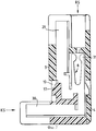
- фиг. 9: разрез кабельного киоска с вкладной ванной и монтажной скобой с колодкой и пылезащитной крышкой;
- фиг. 10: вид спереди монтажной скобы;
- фиг. 11: вид сбоку монтажной скобы из фиг. 10.The invention is explained in more detail below using the drawings, which depict:
- FIG. 1: front view of a block formed by a composite insulating body (upper and lower parts);
- FIG. 2: rear view of the shoe of FIG. 1;
- FIG. 3: bottom view of the shoe of FIG. 1;
- FIG. 4: top view of the block of FIG. 1;
- FIG. 5: section of a shoe along line BB of FIG. 1 with an inserted breaker or switching contact;
- FIG. 6: a top view of the opening or switching contact of FIG. 5;
- FIG. 7: sectional view of the shoe of FIG. 1 with inserted connection pin;
- FIG. 8: top view of the connection pin of FIG. 7;
- FIG. 9: a section of a cable kiosk with a bathtub and mounting bracket with a pad and a dust cover;
- FIG. 10: front view of the mounting bracket;
- FIG. 11: side view of the mounting bracket of FIG. 10.
Присоединительная, размыкающая или коммутирующая колодка используется преимущественно для присоединения кабельных жил в пластиковой изоляции и установочных проводов, например, в концевых муфтах для выполнения, например, кабельных киосков в абонентских кабельных сетях дальней связи. The connecting, disconnecting or switching block is mainly used for connecting cable cores in plastic insulation and installation wires, for example, in terminations for, for example, cable kiosks in subscriber cable telecommunication networks.
Концевая муфта состоит, например, из десяти колодок по десять парных жил, монтажной скобы 9 и маркировочной скобы с табличкой (не показана), которая может быть использована в качестве переходника для корректировки монтажа на стороне кабельных жил. The end sleeve consists, for example, of ten blocks of ten paired cores, a
Конструкция колодок, согласно изобретению, уменьшает размер шага концевой муфты таким образом, что в одной выемке кабельного киоска вместо прежних трех концевых муфт могут быть размещены четыре концевые муфты. Плотность упаковки выводов повышается на 33%, причем в то же время достигаются существенно лучший обзор и больше места для кроссировочного поля. The construction of the blocks according to the invention reduces the step size of the end sleeve in such a way that four end sleeves can be placed in the same recess of the cable kiosk instead of the previous three end sleeves. The packing density of the leads is increased by 33%, and at the same time, a significantly better overview and more space for the crossover field are achieved.
Имеющаяся в распоряжении монтажника площадь увеличивается в кроссировочной зоне на каждый контактный шлиц почти на 40%. The area available to the installer increases in the crossover zone by almost 40% per contact slot.
Благодаря осуществленному в двух плоскостях монтажу колодки, причем сторона кабельных жил лежит внизу, а сторона кроссировочного поля лежит вверху, будучи обращена к монтажнику с поворотом на 90o, можно за счет подходящих средств, например пломбируемой рамы, уменьшить возможность манипуляций на стороне кабельных жил (зона пользователя сети). Разделение стороны пользователя сети и стороны абонента позволяет разделить зоны компетенции.Thanks to the mounting of the block in two planes, the side of the cable cores lying at the bottom and the side of the crossover field at the top, facing the installer with a rotation of 90 o , it is possible to reduce the possibility of manipulation on the side of cable cores by means of suitable means, for example, a sealed frame network user zone). Separation of the network user side and the subscriber side allows the separation of competency areas.
На фиг. 1 - 5 изображена конструкция колодки. Изолирующее тело колодки выполнено разъемным и состоит из верхней 3 и нижней 4 частей, которые после оснащения ножевыми зажимными контактными элементами 7, 8 (фиг. 6, 8) фиксированы между собой под углом 90o посредством выполненных с обеих сторон верхней части 3 фиксирующих отверстий 10 и выполненных с обеих сторон нижней части 4 фиксирующих крюков 37.In FIG. 1 to 5 illustrate the construction of a block. The insulating body of the block is detachable and consists of the upper 3 and lower 4 parts, which, after equipping with knife
Изолирующее тело, образованное верхней 3 и нижней 4 частями (части корпуса), выполнено идентичным для выполнения различных функций колодки (присоединительная, размыкающая или коммутирующая колодка). Различные функции реализуются исключительно за счет оснащения различными ножевыми зажимными контактными элементами на фиг. 6 и 8 и за счет оснащения дополнительными периферийными магазинами и т.п. The insulating body formed by the upper 3 and lower 4 parts (body parts) is made identical to perform various functions of the block (connecting, disconnecting or switching block). Various functions are realized solely by equipping with various knife clamping contact elements in FIG. 6 and 8 and due to equipping with additional peripheral stores, etc.
На фиг. 1 образованная верхней частью 3 зажимная планка 1 имеет контактные шлицы 11, а образованная нижней частью 4 зажимная планка 2 - контактные шлицы 12, которые расположены под углом 90o друг к другу и посредством которых осуществляется соответствующий монтаж.In FIG. 1, the clamping bar 1 formed by the
Зажимная планка 1 образует кроссировочную сторону RS для присоединения отходящих жил абонентской стороны, а зажимная планка 2 - кабельную сторону KS для присоединения входящих жил пользователя сети. The clamping strip 1 forms the crossover side RS for connecting the outgoing wires of the subscriber side, and the clamping strip 2 forms the cable side KS for connecting the incoming wires of the network user.
На фиг. 1 изображены также известные средства 32, 33 для вывода кабельных жил и фиксирующие элементы 5 для защелкивания колодки на монтажной скобе 9 (фиг. 10, 11) или на профиле (не показан). Колодки могут быть соединены произвольно. In FIG. 1 also depicts known means 32, 33 for outputting cable cores and fixing
Простое защелкивание колодок на монтажной скобе 9 исключает сложные работы по свинчиванию и создает, кроме того, возможность отсоединить при необходимости отдельные колодки от монтажной скобы 9 с помощью деблокирующего язычка, отгибаемого монтажным инструментом (не показан). A simple snap-on of the pads on the
Колодки защелкивают на монтажной скобе 9 в соответствии с ее изобретением на фиг. 10, 11 в двух положениях. На фиг. 11 в боковых стенках 34 монтажной скобы 9 изображены два фиксирующих ряда 16, 17. Для удобства монтажа колодки с входящими кабельными жилами с кабельной стороны KS колодку сначала приводят в ее монтажное положение 1 (фиг. 11), для чего фиксирующие элементы 6 (фиг. 2) вставляют в фиксирующие отверстия 18 фиксирующего ряда 16. После этого колодку отсоединяют и, повернув на 90o, приводят в окончательное положение 11 (фиг. 11) путем вставки фиксирующих элементов 5 (фиг. 1 - 4) в фиксирующие отверстия 19 фиксирующего ряда 17 (фиг. 11). Фиксация колодки в окончательном положении 11 может быть устранена только за счет деблокирования с помощью деблокирующего язычка, тогда как фиксация в монтажном положении 1 возможна без вспомогательных средств. Образуется оптически обозримое и по сравнению с уровнем техники существенно большее, обращенное к монтажнику кроссировочное поле, которое обеспечивает надежный и удобный монтаж.The pads snap onto the
Выполнение фиксирующих отверстий 18, 19 в боковых стенках 34 монтажной скобы 9 дает то преимущество, что кромки 35 боковых стенок 34 гладкие и не вызывают опасности травматизма при монтаже колодки. The implementation of the
Монтажная скоба 9 имеет на фиг. 10 прорезь 21 для плавного регулирования кабельных стренг или заглушек, которая обеспечивает удобную кроссировку кабельных стренг на задней стенке монтажной скобы 9 без полного отделения держателя. The
На фиг. 4 изображен вид сверху на колодку, как она представляется монтажнику после ее защелкивания на монтажной скобе 9 в окончательном положении 11. Контактные шлицы 11, 13 расположены, будучи обращены к монтажнику, на стороне RS кроссировочного поля, а контактные шлицы 12 расположены, будучи повернуты на 90o к ним, на кабельной стороне KS. Колодка на фиг. 5 выполнена за счет размещения размыкающего контактного элемента 7 в качестве размыкающей или коммутирующей колодки.In FIG. 4 shows a top view of the block, as it appears to the installer after it clicks on the
Размыкающий контактный элемент 7 на фиг. 5 и 6 состоит из U-образного ножевого зажимного присоединительного контакта 24 с ответвленным контактом 25 и L-образного ножевого зажимного присоединительного контакта 26 с ответвленным контактом 27. Оба ответвленных контакта 25, 27 образуют в плоскости кроссировочной стороны RS функциональный отвод 28, посредством которого вводят отвод 15 любого функционального элемента (не показан) для выполнения нужной функции, например защиты от перенапряжений. Место 14 размыкания может быть выполнено также в качестве места коммутации, причем тогда выгиб 36 колена ответвленного контакта 25 не нужен и колено контакта 25 проходит дальше прямо. The
Отходящие кабельные жилы абонентов подключают к ножевому зажимному присоединительному контакту 24, а входящие кабельные жилы пользователя сети - к ножевому зажимному присоединительному контакту 26, повернутому относительно присоединительного контакта 24 на 90o.Outgoing cable conductors of the subscribers are connected to the knife
На фиг. 6 ножевой зажимной контактный элемент 7 (размыкающий контакт) изображен при виде сверху. In FIG. 6, a knife clamping contact element 7 (opening contact) is shown in a plan view.
На фиг. 7 изображен разрез колодки, выполненной с ножевыми зажимными присоединительными контактами 8 в качестве присоединительной колодки. In FIG. 7 shows a section through a block made with knife clamping connecting
Ножевой зажимной присоединительный контакт 8 выполнен за одно целое из двух ножевых зажимных присоединительных контактов 29, 30, расположенных под углом 90o друг к другу, и из функционального отвода 31.Knife
Функциональный отвод 31 и ножевой зажимной присоединительный контакт 29 доступны с кроссировочной стороны RS, а монтаж ножевого зажимного присоединения 30 следует осуществлять с кабельной стороны KS.
На фиг. 8 изображен вид сверху на ножевой зажимной присоединительный контакт 8, используемый в колодке на фиг. 7. Ножевой зажимной присоединительный контакт 29 отогнут под углом 45o к функциональному отводу 31.In FIG. 8 is a plan view of the knife clamping
На фиг. 9 в схематичном разрезе показано, как контактные элементы защелкнутой на монтажной скобе 9 колодки в значительной степени защищены от загрязнения и образования конденсата за счет защелкивания вкладной ванны 22 на монтажной скобе 9 и за счет пылезащитной крышки 23. In FIG. 9 shows in a schematic section how the contact elements of the pads snapped onto the mounting
Claims (10)
Applications Claiming Priority (2)
| Application Number | Priority Date | Filing Date | Title |
|---|---|---|---|
| DE19652422A DE19652422C1 (en) | 1996-12-09 | 1996-12-09 | Terminal block |
| DE19652422.9 | 1996-12-09 |
Publications (2)
| Publication Number | Publication Date |
|---|---|
| RU97120292A RU97120292A (en) | 1999-10-27 |
| RU2177664C2 true RU2177664C2 (en) | 2001-12-27 |
Family
ID=7814953
Family Applications (1)
| Application Number | Title | Priority Date | Filing Date |
|---|---|---|---|
| RU97120292/09A RU2177664C2 (en) | 1996-12-09 | 1997-12-08 | Connecting, disconnecting, or switching terminal block and method for wiring cable conductors on its terminals |
Country Status (42)
| Country | Link |
|---|---|
| US (1) | US6068503A (en) |
| EP (1) | EP0847106B1 (en) |
| JP (1) | JP4567818B2 (en) |
| KR (1) | KR100499929B1 (en) |
| CN (1) | CN1184723C (en) |
| AP (1) | AP1030A (en) |
| AR (1) | AR009653A1 (en) |
| AT (1) | ATE205967T1 (en) |
| AU (1) | AU740386B2 (en) |
| BA (1) | BA97281A (en) |
| BG (1) | BG63355B1 (en) |
| BR (1) | BR9706242A (en) |
| CA (1) | CA2224036C (en) |
| CO (1) | CO4771006A1 (en) |
| CU (1) | CU22593A3 (en) |
| CY (1) | CY2250B1 (en) |
| CZ (1) | CZ294009B6 (en) |
| DE (2) | DE19652422C1 (en) |
| DK (1) | DK0847106T3 (en) |
| DZ (1) | DZ2365A1 (en) |
| ES (1) | ES2163087T3 (en) |
| HK (1) | HK1015555A1 (en) |
| HR (1) | HRP970669B1 (en) |
| HU (1) | HU222802B1 (en) |
| IL (2) | IL122529A (en) |
| MA (1) | MA24419A1 (en) |
| MY (1) | MY118695A (en) |
| NO (1) | NO318549B1 (en) |
| NZ (1) | NZ329358A (en) |
| PE (1) | PE13599A1 (en) |
| PL (1) | PL183079B1 (en) |
| PT (1) | PT847106E (en) |
| RU (1) | RU2177664C2 (en) |
| SA (1) | SA98180920B1 (en) |
| SG (1) | SG76532A1 (en) |
| SK (1) | SK284329B6 (en) |
| TR (1) | TR199701578A2 (en) |
| TW (1) | TW425739B (en) |
| UA (1) | UA32452C2 (en) |
| UY (1) | UY24803A1 (en) |
| YU (1) | YU48988B (en) |
| ZA (1) | ZA9710978B (en) |
Families Citing this family (27)
| Publication number | Priority date | Publication date | Assignee | Title |
|---|---|---|---|---|
| DE19536224C2 (en) * | 1995-09-28 | 1997-07-31 | Siemens Ag | Connector for a distributor in a telecommunications system |
| DE29807668U1 (en) * | 1998-04-28 | 1998-07-02 | Quante Ag | Terminal block for cables with high transmission rates |
| US6171149B1 (en) * | 1998-12-28 | 2001-01-09 | Berg Technology, Inc. | High speed connector and method of making same |
| DE10001553A1 (en) * | 2000-01-14 | 2001-08-02 | Krone Gmbh | Shielding device for terminal strips |
| KR100498147B1 (en) * | 2000-05-04 | 2005-07-01 | 대유통신 주식회사 | A idc type terminal protection base |
| DE10150045B4 (en) | 2001-10-10 | 2005-06-02 | Krone Gmbh | terminal block |
| DE20203912U1 (en) * | 2002-03-11 | 2003-07-17 | 3M Innovative Properties Co | Connection module of telecommunications technology and combination with a connection module |
| US7155004B1 (en) | 2002-11-22 | 2006-12-26 | Adc Incorporated | System and method of delivering DSL services |
| US7409053B1 (en) * | 2002-11-22 | 2008-08-05 | Adc Telecommunications, Inc. | System and method of providing DSL services on a telephone network |
| US7362590B2 (en) * | 2004-03-31 | 2008-04-22 | Adc Telecommunications, Inc. | Patch panel with modules |
| US7200929B2 (en) * | 2004-03-31 | 2007-04-10 | Adc Telecommunications, Inc. | Patch panel with modules |
| DE102004017605B3 (en) | 2004-04-07 | 2005-10-20 | Adc Gmbh | Connectors for printed circuit boards and distributor connection module |
| US20070047526A1 (en) * | 2005-08-26 | 2007-03-01 | Bryan Kennedy | Systems and methods for conecting between telecommunications equipment |
| US7643631B2 (en) * | 2005-08-26 | 2010-01-05 | Adc Telecommunications, Inc. | Enclosure for broadband service delivery system |
| US7522721B2 (en) * | 2005-08-26 | 2009-04-21 | Adc Telecommunications, Inc. | System for broadband service delivery |
| US7207818B1 (en) | 2005-10-11 | 2007-04-24 | 3M Innovative Properties Company | Telecommunications assembly including at least one telecommunications module |
| DE102007026096A1 (en) * | 2007-06-05 | 2008-12-11 | Adc Gmbh | Cable termination module |
| DE102007026102B3 (en) * | 2007-06-05 | 2008-11-13 | Adc Gmbh | Connectors for printed circuit boards |
| DE102007026111A1 (en) * | 2007-06-05 | 2008-12-11 | Adc Gmbh | Terminal block and contact element for telecommunications and data technology |
| SG152076A1 (en) * | 2007-10-12 | 2009-05-29 | Adc Gmbh | Cross connect block |
| DE102008013317B4 (en) * | 2008-03-10 | 2010-10-14 | Adc Gmbh | Method for producing a wire connection strip with gel filling |
| US7946863B2 (en) * | 2008-04-25 | 2011-05-24 | Adc Telecommunications, Inc. | Circuit protection block |
| US8244089B2 (en) * | 2009-06-03 | 2012-08-14 | Emerson Network Power, Energy Systems, North America, Inc. | Dust caps for fiber optic connectors |
| US7899300B2 (en) * | 2009-06-03 | 2011-03-01 | Emerson Network Power, Energy Systems, North America, Inc. | Dust caps for fiber optic connectors |
| WO2010147749A2 (en) | 2009-06-15 | 2010-12-23 | 3M Innovative Properties Company | Connection and switching contact elements for a termination strip for a telecommunications module |
| EP2566181A1 (en) | 2011-08-31 | 2013-03-06 | 3M Innovative Properties Company | Functional module for a telecommunication strip for a telecommunications system |
| DE102013013458B3 (en) * | 2013-08-14 | 2014-10-30 | Lisa Dräxlmaier GmbH | contact element |
Family Cites Families (13)
| Publication number | Priority date | Publication date | Assignee | Title |
|---|---|---|---|---|
| US3199068A (en) * | 1961-12-12 | 1965-08-03 | Thomas & Betts Corp | Multiple terminal mounting device |
| DE2804478C2 (en) * | 1978-01-31 | 1982-11-25 | Krone Gmbh, 1000 Berlin | Electrical clamp connector for the production of a contact on a fixed connection element without soldering, screwing or stripping, in particular for telecommunication line technology |
| DE2811812C2 (en) * | 1978-03-16 | 1984-04-12 | Krone Gmbh, 1000 Berlin | Cable terminal equipment for telecommunications line technology |
| DE8116614U1 (en) * | 1981-06-04 | 1981-11-05 | Felten & Guilleaume Carlswerk AG, 5000 Köln | Spring clip for connecting isolated electrical conductors |
| US4789354A (en) * | 1987-09-14 | 1988-12-06 | Minnesota Mining And Manufacturing Company | Voice/data communication termination connector |
| ATE117132T1 (en) * | 1990-03-13 | 1995-01-15 | Krone Ag | CONNECTION BLOCK FOR TELECOMMUNICATIONS AND DATA TECHNOLOGY. |
| US5147218A (en) * | 1991-04-12 | 1992-09-15 | Minnesota Mining And Manufacturing Company | Pluggable modular splicing connector and bridging adapter |
| US5364288A (en) * | 1992-07-24 | 1994-11-15 | North American Philips Corporation | Electrical connecting device |
| DE4325952C2 (en) * | 1993-07-27 | 1997-02-13 | Krone Ag | Terminal block for high transmission rates in telecommunications and data technology |
| EP0644609B1 (en) * | 1993-09-18 | 1998-02-18 | Molex Incorporated | Flat insulation displacement terminal for electrical connectors |
| DE9400303U1 (en) * | 1994-01-10 | 1995-02-09 | Krone Ag | Connection module |
| JP2942979B2 (en) * | 1994-11-21 | 1999-08-30 | モレックス インコーポレーテッド | Electrical connector |
| US5722850A (en) * | 1995-11-27 | 1998-03-03 | Molex Incorporated | Telecommunications connectors |
-
1996
- 1996-12-09 DE DE19652422A patent/DE19652422C1/en not_active Expired - Lifetime
-
1997
- 1997-12-04 BG BG102103A patent/BG63355B1/en unknown
- 1997-12-04 CZ CZ19973873A patent/CZ294009B6/en not_active IP Right Cessation
- 1997-12-05 AT AT97121398T patent/ATE205967T1/en active
- 1997-12-05 PT PT97121398T patent/PT847106E/en unknown
- 1997-12-05 DK DK97121398T patent/DK0847106T3/en active
- 1997-12-05 AR ARP970105720A patent/AR009653A1/en unknown
- 1997-12-05 PE PE1997001098A patent/PE13599A1/en not_active Application Discontinuation
- 1997-12-05 EP EP97121398A patent/EP0847106B1/en not_active Expired - Lifetime
- 1997-12-05 DE DE59704653T patent/DE59704653D1/en not_active Expired - Lifetime
- 1997-12-05 ES ES97121398T patent/ES2163087T3/en not_active Expired - Lifetime
- 1997-12-08 NZ NZ329358A patent/NZ329358A/en not_active IP Right Cessation
- 1997-12-08 CA CA002224036A patent/CA2224036C/en not_active Expired - Fee Related
- 1997-12-08 SK SK1692-97A patent/SK284329B6/en not_active IP Right Cessation
- 1997-12-08 DZ DZ970215A patent/DZ2365A1/en active
- 1997-12-08 NO NO19975768A patent/NO318549B1/en not_active IP Right Cessation
- 1997-12-08 MA MA24891A patent/MA24419A1/en unknown
- 1997-12-08 UA UA97125880A patent/UA32452C2/en unknown
- 1997-12-08 MY MYPI97005897A patent/MY118695A/en unknown
- 1997-12-08 CU CU1997138A patent/CU22593A3/en unknown
- 1997-12-08 ZA ZA9710978A patent/ZA9710978B/en unknown
- 1997-12-08 HR HR970669A patent/HRP970669B1/en not_active IP Right Cessation
- 1997-12-08 US US08/986,393 patent/US6068503A/en not_active Expired - Lifetime
- 1997-12-08 RU RU97120292/09A patent/RU2177664C2/en not_active IP Right Cessation
- 1997-12-08 AP APAP/P/1998/001188A patent/AP1030A/en active
- 1997-12-09 IL IL12252997A patent/IL122529A/en not_active IP Right Cessation
- 1997-12-09 IL IL12251997A patent/IL122529A0/en unknown
- 1997-12-09 CN CNB971297193A patent/CN1184723C/en not_active Expired - Lifetime
- 1997-12-09 TR TR97/01578A patent/TR199701578A2/en unknown
- 1997-12-09 SG SG1997004377A patent/SG76532A1/en unknown
- 1997-12-09 BA BA970281A patent/BA97281A/en unknown
- 1997-12-09 PL PL97323613A patent/PL183079B1/en unknown
- 1997-12-09 KR KR1019970066959A patent/KR100499929B1/en not_active IP Right Cessation
- 1997-12-09 BR BR9706242A patent/BR9706242A/en not_active IP Right Cessation
- 1997-12-09 CO CO97071822A patent/CO4771006A1/en unknown
- 1997-12-09 YU YU47997A patent/YU48988B/en unknown
- 1997-12-09 HU HU9702378A patent/HU222802B1/en active IP Right Grant
- 1997-12-09 JP JP33862797A patent/JP4567818B2/en not_active Expired - Fee Related
- 1997-12-09 TW TW086118541A patent/TW425739B/en not_active IP Right Cessation
- 1997-12-09 AU AU47649/97A patent/AU740386B2/en not_active Ceased
- 1997-12-09 UY UY24803A patent/UY24803A1/en not_active IP Right Cessation
-
1998
- 1998-03-01 SA SA98180920A patent/SA98180920B1/en unknown
-
1999
- 1999-01-21 HK HK99100289A patent/HK1015555A1/en not_active IP Right Cessation
-
2001
- 2001-11-28 CY CY0100042A patent/CY2250B1/en unknown
Also Published As
Similar Documents
| Publication | Publication Date | Title |
|---|---|---|
| RU2177664C2 (en) | Connecting, disconnecting, or switching terminal block and method for wiring cable conductors on its terminals | |
| RU2133071C1 (en) | Modified cross-connection system for telecommunication lines | |
| RU97120292A (en) | CONNECTING, OPENING OR SWITCHING BODY AND METHOD FOR INSTALLING CABLE VEINS ON THE CLAMPING ELEMENTS OF THE INDICATED BODY | |
| EP0434964B1 (en) | A set of assembly elements intended to facilitate concurrent electrical connection of a plurality of modular automatic circuit breakers | |
| US5412715A (en) | Apparatus and method for connecting telephone switching devices | |
| FI90293B (en) | Contact list for cable lines, especially for telephone cables | |
| HU218951B (en) | Distributor for telecommunication and data transmission systems, as well as mounting bracket and a cable guide arrangement for said distributor | |
| PL209001B1 (en) | Connecting block for cross connections | |
| SK123596A3 (en) | Grounding stirrup, particularly for use in connecting device for telecommunication and data technology | |
| US5928008A (en) | Earthing module | |
| US5991140A (en) | Technique for effectively re-arranging circuitry to realize a communications service | |
| EP1770832B1 (en) | Telecommunications plug, an assembly including a telecommunications module and a plug, and a method of manufacturing a plug | |
| HUT77151A (en) | Catv tap | |
| US6065975A (en) | Connector switching mechanism | |
| US6083011A (en) | Connector switching mechanism with improved cap retention | |
| AU710095B2 (en) | An intermediate coupling device in a telecommunication system | |
| EP1158612B1 (en) | Telecommunications connector | |
| MXPA97009796A (en) | Connection, cut or shuttle rules | |
| CN101133526A (en) | Telecommunications module assemblies thereof and methods of making and using same | |
| EP0964491B1 (en) | A structure with a main support and an additional support for the connection of a removable accessorised electrical device | |
| CA2201125A1 (en) | Catv tap | |
| GB2364185A (en) | Holder for electrical connectors and enclosure having a crimping tool | |
| TWI335695B (en) | ||
| WO2018039767A1 (en) | Electrical connector assembly | |
| JPH03257774A (en) | Connector structure for belt-foil formed conductive material and its male connector |
Legal Events
| Date | Code | Title | Description |
|---|---|---|---|
| MM4A | The patent is invalid due to non-payment of fees |
Effective date: 20131209 |