RU217543U1 - steering gear for vehicle - Google Patents
steering gear for vehicle Download PDFInfo
- Publication number
- RU217543U1 RU217543U1 RU2022135031U RU2022135031U RU217543U1 RU 217543 U1 RU217543 U1 RU 217543U1 RU 2022135031 U RU2022135031 U RU 2022135031U RU 2022135031 U RU2022135031 U RU 2022135031U RU 217543 U1 RU217543 U1 RU 217543U1
- Authority
- RU
- Russia
- Prior art keywords
- steering
- pendulum
- lever
- cardan
- pendulum lever
- Prior art date
Links
Images


Abstract
Полезная модель относится к области транспортного машиностроения, в частности к механизмам рулевого управления транспортных средств повышенной проходимости, предназначенных для движения по грунтам с малой несущей способностью и неровностями, которые вызывают значительные хода подвески жестких мостов и управляемых колес. Техническим результатом предлагаемого решения является повышение надежности и безопасности рулевого управления для транспортных средств повышенной проходимости. Рулевой механизм содержит рулевую колонку 1, карданную передачу 2, которая соединена с маятниковым рычагом 3. На маятниковом рычаге смонтирована сошка 4, которая посредством рулевой тяги 5 соединена с рычагом поворотного кулака 7. Маятниковый рычаг 3 закреплен на балке моста 6. Представленная кинематика рулевого управления достигается применением в рулевом приводе карданной передачи с переменной длиной. Для этого между карданной передачей 2 и маятниковым рычагом 3 включено дополнительное звено, которое и обеспечивает получение заявленного технического результата. Карданная передача переменной длины 2 показана на фиг. 2 и представляет собой комбинацию двух крестовин 9, соединенных между собой специальным звеном 10. Маятниковый рычаг 3 показан на фиг. 3 и представляет собой поворотную опору, состоящую из оси маятника 11 и корпусных подшипников 12. Конструктивно сошка 4 может быть установлена как на ось маятника 11, так и на нижний шарнир 9 карданной передачи 2. 2 з.п. ф-лы, 3 ил.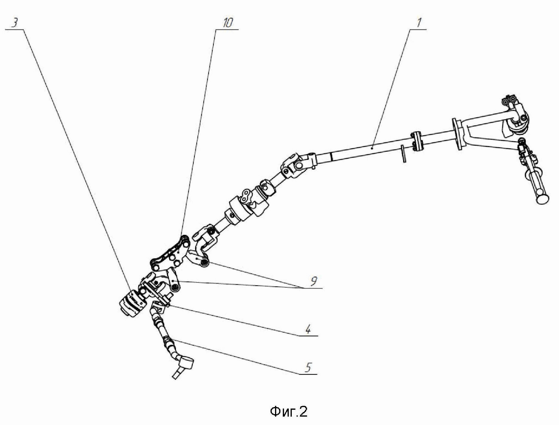
Description
Полезная модель относится к области транспортного машиностроения, в частности к механизмам рулевого управления транспортных средств повышенной проходимости, предназначенных для движения по грунтам с малой несущей способностью и неровностями, которые вызывают значительные хода подвески жестких мостов и управляемых колес. Одной из проблем создания рулевого управления для вездеходов и другой колесной техники повышенной проходимости является несоответствие кинематики подвески и рулевого управления при больших ходах управляемых колес на элементах подвески.The utility model relates to the field of transport engineering, in particular to the steering mechanisms of cross-country vehicles intended for movement on soils with low bearing capacity and unevenness, which cause significant suspension travel of rigid axles and steered wheels. One of the problems of creating steering for all-terrain vehicles and other off-road wheeled vehicles is the discrepancy between the kinematics of the suspension and steering at large strokes of the steered wheels on the suspension elements.
При наезде на ощутимое препятствие хотя бы одним колесом, происходит непроизвольный поворот управляемых колес в сторону препятствия. Это происходит вследствие того, что сошка рулевой колонки, находящаяся на подрессоренной раме ТС, связана с поворотным рычагом, находящимся на поворотном кулаке неподрессоренного моста, посредством рулевой тяги конечной длины. Работа подвески по вертикали воспринимается управляемым колесом как поворот рулевого колеса. Происходит нежелательное самопроизвольное руление транспортного средства при перемещениях переднего моста в момент сжатия и отбоя передней подвески. Данный эффект значительно снижает скорость прохождения неровных участков поверхности, вызывает дискомфорт при управлении и негативно влияет на безопасность и эксплуатационные качества транспортного средства.When hitting a tangible obstacle with at least one wheel, the steered wheels involuntarily turn towards the obstacle. This is due to the fact that the bipod of the steering column, located on the sprung frame of the vehicle, is connected to the swing arm, located on the steering knuckle of the unsprung axle, by means of a tie rod of finite length. The operation of the suspension vertically is perceived by the steered wheel as a turn of the steering wheel. An undesirable spontaneous steering of the vehicle occurs when the front axle is moved at the time of compression and rebound of the front suspension. This effect significantly reduces the speed of passing uneven surface areas, causes discomfort when driving and negatively affects the safety and performance of the vehicle.
Известна конструкция рулевого привода, содержащая в своем составе эластичный элемент в виде пружины определенной жесткости и демпфирующий элемент с определенным коэффициентом демпфирования (см. патент DE 19511273, публ. от 05.10.1995).Known for the design of the steering drive, containing in its composition an elastic element in the form of a spring of a certain stiffness and a damping element with a certain damping coefficient (see patent DE 19511273, publ. from 05.10.1995).
Недостатком этого известного технического решения является сложность конструкции и определенные трудности при расчете, подборе и изготовлении пружин определенной жесткости и демпфирующих элементов с определенным коэффициентом демпфирования.The disadvantage of this well-known technical solution is the complexity of the design and certain difficulties in the calculation, selection and manufacture of springs of a certain stiffness and damping elements with a certain damping coefficient.
Известно также рулевое управление транспортного средства по патенту РФ №2139200 от 4.12.98 г., состоящее из рулевой колонки, рулевого механизма, сошки, продольной тяги, двуплечего рычага, поперечной тяги, коромысла и поворотного рычага, при этом ось перемещения поперечной тяги совпадает с осью вращения рычага подвески, выполненной полой в месте крепления к борту транспортного средства.It is also known the steering of the vehicle according to the patent of the Russian Federation No. 2139200 dated 4.12.98, consisting of a steering column, a steering mechanism, a bipod, a longitudinal thrust, a two-arm lever, a transverse thrust, a rocker arm and a rotary lever, while the axis of movement of the transverse thrust coincides with axis of rotation of the suspension arm, made hollow at the point of attachment to the side of the vehicle.
Недостатком этого рулевого механизма является его ограниченная область применения только для транспортных средств типа «амфибия». Для транспортных средств повышенной проходимости с возможностью форсировать вплавь водные преграды при помощи шин сверхнизкого давления данное техническое решение будет излишним и не выполнять описанные преимущества относительно других рулевых механизмов.The disadvantage of this steering mechanism is its limited scope only for amphibious vehicles. For off-road vehicles with the ability to cross water obstacles using ultra-low pressure tires, this technical solution will be redundant and will not fulfill the described advantages relative to other steering mechanisms.
Наиболее близким решением к предлагаемой конструкции можно считать рулевой механизм по патенту RU 2692517, приоритет DE от 27.10.2015 г., публ. от 25.06.2019, состоящий из рулевой колонки, рулевого механизма, сошки, продольной тяги и поперечной тяги, при этом продольная тяга является рулевой тягой сошки и совпадает с продольной осью транспортного средства. Эффект «подруливания» управляемых колес этого рулевого механизма уменьшается за счет оптимальной геометрии расположения рулевой тяги и продольной направляющей передней подвески. В этом случае продольная тяга значительной длины располагается продольно вдоль оси транспортного средства и составляет с продольной направляющей передней подвески правильный параллелограмм. Дополнительно продольные перемещения рулевой тяги гасятся промежуточными механизмами (зубчатый редуктор, гидравлический редуктор, коническая зубчатая передача, ременная передача) за счет передаточного числаThe closest solution to the proposed design can be considered a steering mechanism according to patent RU 2692517, priority DE dated October 27, 2015, publ. dated 06/25/2019, consisting of a steering column, a steering mechanism, a bipod, a longitudinal link and a transverse link, while the longitudinal link is the steering link of the bipod and coincides with the longitudinal axis of the vehicle. The effect of "steering" the steered wheels of this steering mechanism is reduced due to the optimal geometry of the location of the steering rod and the longitudinal guide of the front suspension. In this case, a longitudinal link of considerable length is located longitudinally along the axis of the vehicle and forms a regular parallelogram with the longitudinal guide of the front suspension. Additionally, longitudinal movements of the steering rod are damped by intermediate mechanisms (gear reducer, hydraulic reducer, bevel gear, belt drive) due to the gear ratio
Недостатком этого технического решения является сложность конструкции, наличие дополнительных механизмов, большая длина и продольное расположение рулевой тяги. Описанная конструкция не может быть реализована на транспортных средствах, в которых рулевая колонка не имеет механической связи с рулевым механизмом.The disadvantage of this technical solution is the complexity of the design, the presence of additional mechanisms, the large length and longitudinal arrangement of the steering rod. The described construction cannot be implemented on vehicles in which the steering column is not mechanically connected to the steering mechanism.
Техническим результатом предлагаемого решения является повышение надежности и безопасности рулевого управления для транспортных средств повышенной проходимости.The technical result of the proposed solution is to increase the reliability and safety of steering for cross-country vehicles.
Для достижения заявленного технического результата в конструкцию рулевого механизма внесены изменения, а именно карданная передача выполнена с возможностью изменения длины и включает две крестовины, соединенные между собой звеном, а маятниковый рычаг выполнен с возможностью закрепления на балке моста транспортного средства и представляет собой поворотную опору, состоящую из оси маятника и корпусных подшипников.To achieve the claimed technical result, changes have been made to the design of the steering mechanism, namely, the cardan gear is made with the possibility of changing the length and includes two crosses connected to each other by a link, and the pendulum lever is made with the possibility of being fixed on the beam of the bridge of the vehicle and is a rotary support, consisting from the axis of the pendulum and housing bearings.
Кроме того, в предлагаемом рулевом механизме сошка установлена на ось маятникового рычага, а звено, соединяющее две крестовины, выполнено в виде двух щек с гнездами для игольчатых подшипников.In addition, in the proposed steering mechanism, the bipod is mounted on the axis of the pendulum lever, and the link connecting the two crosspieces is made in the form of two cheeks with sockets for needle bearings.
Выполнение карданной передачи переменной длины, связанной с маятниковым рычагом, позволяет компенсировать перемещения рулевой тяги, вызванные вертикальным перемещением управляемых колес при ходах подвески транспортного средства повышенной проходимости. Это обеспечивает надежность и безопасность управления транспортным средствомThe implementation of a cardan transmission of variable length associated with the pendulum lever allows you to compensate for the movement of the steering rod caused by the vertical movement of the steered wheels during the suspension travels of the off-road vehicle. This ensures the reliability and safety of driving a vehicle.
Предлагаемый рулевой механизм показан на фиг. 1, где обозначены:The proposed steering mechanism is shown in Fig. 1, where are indicated:
1 - рулевая колонка;1 - steering column;
2 - карданная передача переменной длины;2 - cardan transmission of variable length;
3 - маятниковый рычаг;3 - pendulum lever;
4 - сошка;4 - bipod;
5 - рулевая тяга;5 - tie rod;
6 - балка моста;6 - bridge beam;
7 - рычаг поворотного кулака;7 - steering knuckle lever;
8 - поперечная тяга;8 - transverse thrust;
9 - крестовины;9 - crosses;
10 - звено, соединяющее крестовины;10 - a link connecting the crosses;
11 - ось маятника;11 - axis of the pendulum;
12 - корпусные подшипники.12 - housing bearings.
Рулевой механизм содержит рулевую колонку 1, карданную передачу 2, которая соединена с маятниковым рычагом 3. На маятниковом рычаге смонтирована сошка 4, которая посредством рулевой тяги 5 соединена с рычагом поворотного кулака 7. Маятниковый рычаг 3 закреплен на балке моста 6. Представленная кинематика рулевого управления достигается применением в рулевом приводе карданной передачи с переменной длиной. Для этого между карданной передачей 2 и маятниковым рычагом 3, включено дополнительное звено, которое и обеспечивают получение заявленного технического результата.The steering mechanism includes a
Карданная передача переменной длины 2 показана на фиг. 2 и представляет собой комбинацию двух крестовин 9, соединенных между собой специальным звеном 10 в виде двух щек с гнездами для игольчатых подшипников. Данное звено обеспечивает необходимую подвижность шарнира 2, при этом ограничивает предельные углы для предотвращения переламывания шарнира и переход в нештатный режим работы. Ход шарнира - разница длин от полностью сложенного положения до полностью растянутого составляет 175 мм, что позволяет компенсировать практически полный ход передней подвески.A variable
Маятниковый рычаг 3 показан на фиг. 3 и представляет собой поворотную опору, состоящую из оси маятника 11 и корпусных подшипников 12. Конструктивно сошка 4 может быть установлена как на ось маятника 11, так и на нижний шарнир 9 карданной передачи 2.The
Принцип действия предлагаемого рулевого механизма заключается в следующем: вертикальные перемещения балки моста 6 передаются на карданные шарниры 2, которые при складывании или растяжении компенсируют эти перемещения. Сошка 4, находясь на маятниковом рычаге 3 на балке моста 6, перемещается вместе с мостом. Предлагаемая кинематика не передает колебания подвески непосредственно на рулевой вал 1, а гасит эти колебания за счет работы карданных шарниров.The principle of operation of the proposed steering mechanism is as follows: the vertical movement of the
Таким образом, предлагаемый рулевой механизм отличается от известных конструкций того же назначения следующими признаками:Thus, the proposed steering mechanism differs from the known designs of the same purpose by the following features:
рулевая тяга не связана механической связью с рулевым механизмом, а соединяется с сошкой, расположенной непосредственно на рулевой колонке;the steering rod is not mechanically connected to the steering mechanism, but is connected to a bipod located directly on the steering column;
рулевая тяга располагается поперек транспортного средства, имеет небольшие габаритные размеры;the steering rod is located across the vehicle, has small overall dimensions;
не требует внесения изменений в штатные рулевые приводы, применяемые на транспортных средствах высокой проходимости;does not require changes to standard steering gears used on off-road vehicles;
не требует применения промежуточных передаточных механизмов типа конических, зубчатых, гидравлических или ременных передач.does not require the use of intermediate transmission mechanisms such as bevel, gear, hydraulic or belt drives.
Предлагаемый механизм прост в изготовлении, использует элементы рулевых механизмов, применяемых в автомобилестроении, стандартные узлы и детали, которые можно приобрести в свободной продаже.The proposed mechanism is easy to manufacture, uses elements of steering mechanisms used in the automotive industry, standard components and parts that can be purchased on the open market.
Использование предлагаемого изобретения позволит повысить безопасность и эксплуатационную скорость транспортных средств высокой проходимости при движении по участкам пересеченной местности с большими ходами подвески.The use of the invention will improve the safety and operating speed of off-road vehicles when driving on rough terrain with large suspension travel.
Claims (3)
Publications (1)
| Publication Number | Publication Date |
|---|---|
| RU217543U1 true RU217543U1 (en) | 2023-04-04 |
Family
ID=
Citations (3)
| Publication number | Priority date | Publication date | Assignee | Title |
|---|---|---|---|---|
| DE19511273A1 (en) * | 1994-03-28 | 1995-10-05 | Nissan Motor | Steering system for motor vehicle |
| RU2692517C1 (en) * | 2015-10-27 | 2019-06-25 | Кнорр-Бремзе Зюстеме Фюр Нутцфарцойге Гмбх | Steering mechanism for a vehicle, a vehicle, a steering mechanism control method and a vehicle control method |
| RU2786903C1 (en) * | 2022-07-27 | 2022-12-26 | Общество с ограниченной ответственностью "Сергеев Динамикс" | All-wheel drive off-road vehicle with electric wheel drive |
Patent Citations (3)
| Publication number | Priority date | Publication date | Assignee | Title |
|---|---|---|---|---|
| DE19511273A1 (en) * | 1994-03-28 | 1995-10-05 | Nissan Motor | Steering system for motor vehicle |
| RU2692517C1 (en) * | 2015-10-27 | 2019-06-25 | Кнорр-Бремзе Зюстеме Фюр Нутцфарцойге Гмбх | Steering mechanism for a vehicle, a vehicle, a steering mechanism control method and a vehicle control method |
| RU2786903C1 (en) * | 2022-07-27 | 2022-12-26 | Общество с ограниченной ответственностью "Сергеев Динамикс" | All-wheel drive off-road vehicle with electric wheel drive |
Similar Documents
| Publication | Publication Date | Title |
|---|---|---|
| US10023019B2 (en) | Rear suspension systems with rotary devices for laterally tiltable multitrack vehicles | |
| US2369501A (en) | Axle guiding arrangement | |
| US3419100A (en) | Wheel suspension of driven wheels, especially of the rear wheels of a motor vehicle | |
| US2692778A (en) | Rocking axle suspension for motor vehicles | |
| EP2712796B1 (en) | Wheel suspension for an inclining vehicle | |
| CN107662665B (en) | Multi-wheel mobile platform with variable wheelbase | |
| JPS5996008A (en) | Vehicle suspension system | |
| US12233968B2 (en) | Track kit | |
| KR20100016064A (en) | Roll-stabilizing fifth wheel apparatus | |
| CN112829579B (en) | A new power transmission structure suitable for all-terrain karts | |
| US7784807B2 (en) | Wheel suspension for motor vehicles | |
| US6619417B2 (en) | Snowmobile slide rail system | |
| US4865350A (en) | Vehicle suspension system | |
| US3948337A (en) | Independent front suspension for front wheel drive | |
| US11117436B2 (en) | Vehicle suspension system | |
| RU217543U1 (en) | steering gear for vehicle | |
| CN109130745B (en) | A four-wheel drive off-road vehicle with a wheel adjustment linkage mechanism | |
| US4046212A (en) | Steerable front wheel drive transmitting mechanism | |
| CN113263882A (en) | Anti-roll bar structure of FSAE racing car double-cross-arm suspension | |
| US20110148066A1 (en) | Vehicle suspension, steering, damping and anti-roll system with linear wheel travel | |
| US3073616A (en) | Steering arrangement for automotive vehicles | |
| GB427907A (en) | Improvements in or relating to resilient suspension systems for vehicles | |
| US2112133A (en) | Motor vehicle | |
| RU2851525C1 (en) | Universal drive axle for motor vehicle | |
| US2107183A (en) | Stabilizing means for motor vehicles |